Grizzly G0566B User manual

COPYRIGHT © JUNE, 2008 BY GRIZZLY INDUSTRIAL, INC.
WARNING: NO PORTION OF THIS MANUAL MAY BE REPRODUCED IN ANY SHAPE
OR FORM WITHOUT THE WRITTEN APPROVAL OF GRIZZLY INDUSTRIAL, INC.
#BL10789 PRINTED IN TAIWAN
The Model G0531B/G0566B is the same as the Model G0566, except it has a magnetic brake motor, resaw
fence, and square fence rail. Besides the instructions, data sheet, circuit requirements, parts, and wiring
diagram in this insert, the content in the Model G0566 owner's manual is the same for both machines.
Before operating your new machine, you MUST read and understand this insert and the entire Model G0566
manual to reduce the risk of injury from improper use or setup.
If you have any further questions about this manual insert or the differences between the Model G0531B/
G0566B and the Model G0566, contact our Technical Support at (570) 546-9663 or email techsupport@
grizzly.com.
MODEL G0531B/G0566B
21" BANDSAW
w/MOTOR BRAKE
MANUAL INSERT
Machine Inventory
After all the parts have been removed from the
crate, you should have the following items:
Crate Contents (Figure 1): Qty
A. Bandsaw (not shown) ................................. 1
B. Miter Gauge ................................................ 1
C. Fence.......................................................... 1
D. Resaw Fence ............................................. 1
E. Guide Post Handwheel............................... 1
Figure 1. G0531B/G0566B inventory.
BC
ED
Hardware and Tools (not shown) Qty
Hex Wrench 5mm .............................................. 1
Hex Wrench 6mm .............................................. 1
Open End Wrench 10 x 13 ................................ 1
Open End Wrench 17 x 19 ................................ 1
Lifting Rings ....................................................... 2
Resaw Fence Lock Handle M8-1.25 x 44
(Fence) .............................................................. 1
Moving Plate M8-1.25 (Fence) .......................... 1
Flat Washer 8mm (Fence) ................................ 1
Installing Fence
Components and Hardware Needed: Qty
Fence Assembly ................................................ 1
Resaw Fence Assembly .................................... 1
Resaw Fence Lock Handle M8-1.25 x 44 ......... 1
Moving Plate M8-1.25 ....................................... 1
Flat Washer 8mm .............................................. 1
To install the fence:
1. Remove the cap screw, knobs, and washers
that hold the rail onto the table, then remove
the rail.
2. Flip the rail over and reinstall with the fast-
ners removed in Step 1.
3. Install the fence handle on the fence, if it is
not already installed.
Model G0531B/G0566B-2-
Test Run
1. Follow Steps 1-3 in the G0566 Manual on
Page 24.
2. Verify that the machine is operating correctly
by turning the switch disabling key (Figure 4)
to "1" and turning the machine ON.
—When operating correctly, the machine
runs smoothly with little or no vibration or
rubbing noises.
— Investigate and correct strange or unusual
noises or vibrations before operating the
machine further. Always disconnect the
machine from power when investigating or
correcting potential problems.
3. Press the OFF button to stop the machine.
4. WITHOUT resetting the OFF button, press
the ON button. The machine should not
start.
—If the machine does not start, the OFF but-
ton safety feature is working correctly.
—If the machine does start (with the stop
button pushed in), immediately disconnect
power to the machine. The OFF button
safety feature is not working correctly. This
safety feature must work properly before
proceeding with regular operations. Call
Tech Support for help.
Figure 4. G0531B switch disabling key and ON/
OFF switch.
Figure 3. Example of attaching resaw fence to
standard fence.
Moving
Plate
Resaw Fence
Resaw Lock
Handle
Figure 2. Fence handle components.
Pivot Block
Hex Nut
Fence
Handle
4. Tighten the hex nut on the fence handle
against the fence pivot block (Figure 2).
6. Tighten the resaw lock handle.
7. Pull the fence handle up and place the fence
assembly on the rail.
8. Push the fence handle down to lock the fence
assembly in place.
5. Install the resaw fence lock handle (with the
8mm washer and moving plate) onto the
fence, then slide the resaw fence over the
moving plate as shown in Figure 3.
Note: Leave the moving plate and lock
handle loose enough to slide on the resaw
fence.

Model G0531B/G0566B -3-
7. Try to turn the machine ON.
—If the bandsaw does not start, the switch
disabling feature is working as designed.
The Test Run is complete.
—If the bandsaw starts, immediately discon-
nect power. The switch disabling feature is
not working correctly. This safety feature
must work properly before proceeding with
regular operations. Call Tech Support for
help.
OFF Button
T
W
I
S
T
Figure 5. Resetting the switch.
6. Turn the switch disabling key to "0", as shown
in Figure 4.
5. Twist the OFF button clockwise so it pops
out. When the OFF button pops out, the
switch is reset and ready for operation (see
Figure 5).
Motor Brake
The motor brake is activated automatically when
the OFF button is pushed, quickly bringing the
blade to a stop.
4. Adjust the fence face parallel with the edge of
the miter slot, as shown in Figure 6.
Aligning Fence
To ensure cutting accuracy when the fence is first
installed, the fence should be aligned with the
miter slot.
To align the fence parallel with the miter slot:
1. DISCONNECT BANDSAW FROM POWER!
2. Make sure the miter slot is aligned with the
bandsaw blade (see G0566 Manual Page 22,
Table Alignment).
3. Mount the fence next to the miter slot, then
loosen the knobs and cap screw that secure
the fence rail to the table.
NOTICE
Adjusting the fence parallel to the miter
slot does not guarantee straight cuts. The
miter slot may need to be adjusted paral-
lel to the side of the blade. Refer to the
"Table Alignment" instructions in the G0566
Manual on Page 22.
5. Tighten the knobs and cap screw that secure
the rail to the table, being careful not to move
the fence.
Figure 6. Example of fence square with miter
slot.

Model G0531B/G0566B-4-
Magnetic Brake Adjustment
The space between the magnetic brake and brake
shoe is preset by the factory at 0.2mm (0.008").
However, you should adjust this space every two
to three years, or when it takes over five seconds
for the brake to stop the motor.
Tools Needed
Phillips Head Screwdriver ................................. 1
US Dollar Bills or Feeler Gauges 0.008" .......... 2
Hex Wrench 3mm .............................................. 1
Hex Wrench 4mm .............................................. 1
To adjust the space between the magnetic
brake and brake shoe:
1. DISCONNECT BANDSAW FROM POWER!
2. Remove the motor fan cover, then loosen the
cap screws securing the motor fan and brake
shoe (see Figure 7).
Accessories
Replacement Blades
Replacement blades for the Model G0531B/
G0566B Industrial Bandsaw. Hook blades are
signifed by the H after the TPI, and raker blades
are signified by the R after TPI.
165" Steel Replacement Blades for the Model
G0531B and G0566B
Figure 7. Adjusting distance between magnetic
brake and brake shoe.
Magnetic
Brake
Cap
Screw
Motor
Fan
Brake
Shoe
OFF
ON
3. Fold two dollar bills in half and slide them
(or use feeler gauges) between the brake
shoe and magnetic brake on both sides (see
Figure 7).
4. Slide the fan toward the brake until you feel
a slight resistance when moving the bill, then
tighten the cap screws on the brake shoe and
motor fan, then reinstall the motor fan cover.
MODEL TYPE WIDTH GAUGE TPI
H6978 Carbon 1/2" 0.025" 3H
H6979 Carbon 1/2" 0.025" 4H
H6980 Carbon 1/2" 0.025" 6H
H6981 Carbon 1/2" 0.025" 10R
H6982 Carbon 1/2" 0.025" 14R
H6983 Carbon 1" 0.035" 2H
H6984 Carbon 1" 0.035" 6H
H6985 Carbon 1" 0.035" 10R
H6986 Carbon 11/4" 0.035" 1.3H
H6987 Carbon 1" 0.025" 3H
Figure 8. Model T10131 Extension Table
attached to G0566B bandsaw.
T10131—Extension Table for G0531B/G0566B
Easily attaches to the main table of your bandsaw
and provides additional support for large
workpieces.

Model G0531B/G0566B -5-
MODEL G0531B
21" 5HP HEAVY-DUTY BANDSAW w/MOTOR BRAKE
Customer Service #: (570) 546-9663 • To Order Call: (800) 523-4777 • Fax #: (800) 438-5901
MACHINE DATA
SHEET
Product Dimensions:
Weight ........................................................................................................................................................................... 594 lbs.
Length/Width/Height ....................................................................................................................................321⁄4" x 391⁄2" x 78"
Foot Print (Length/Width) ....................................................................................................................................... 215⁄8" x 331⁄2"
Shipping Dimensions:
Type ................................................................................................................................................................. Wood Slat Crate
Content .......................................................................................................................................................................... Machine
Weight ............................................................................................................................................................................ 695 lbs.
Length/Width/Height .........................................................................................................................................303⁄8" x 39" x 87"
Electrical:
Switch ........................................................................................................................ Magnetic w/Thermal Overload Protection
Switch Voltage ................................................................................................................................................................... 220V
Recommended Circuit Size ............................................................................................................................................30 amp
Recommended Plug Type .................................................................................................................................................L6-30
Plug Included ......................................................................................................................................................................... No
Motor:
Type ......................................................................................................................................... TEFC Capacitor Start Induction
Horsepower .........................................................................................................................................................................5 HP
Voltage ............................................................................................................................................................................... 220V
Phase ................................................................................................................................................................................Single
Amps .................................................................................................................................................................................... 22A
Speed .........................................................................................................................................................................1725 RPM
Cycle ................................................................................................................................................................................. 60 Hz
Number Of Speeds ...................................................................................................................................................................1
Power Transfer ...........................................................................................................................................................Belt Drive
Bearings ......................................................................................................................... Shielded and Permanently Lubricated
Brake ......................................................................................................................................... Built-In Magnetic Type, 90VDC
Main Specifications:
Operation Information
Blade Speed ..................................................................................................................................................... 4600 FPM
Table Tilt ................................................................................................................................................ Left 5°, Right 45°
Cutting Capacities
Maximum Cutting Height ............................................................................................................................................. 14"
Throat Capacity Left of Blade ...................................................................................................................................... 20"
Blade Information
Standard Blade Length .............................................................................................................................................. 165"
Blade Width Range .............................................................................................................................................. 1⁄4"–13⁄8"
Blade Guides ................................................................................................................................................. Ball Bearing
Model G0531B Page 1 of 2

Model G0531B/G0566B-6-
Table Information
Table Length ............................................................................................................................................................ 29
1⁄2"
Table Width ...............................................................................................................................................................203⁄4"
Table Thickness ......................................................................................................................................................... 1
7⁄8"
Floor to Table Height .................................................................................................................................................351⁄2"
Fence Information
Locks in Front ..............................................................................................................................................................Yes
Locks in Rear ............................................................................................................................................................... No
Adjustable for Blade Lead ............................................................................................................................................ No
Resaw Fence Plate Height ............................................................................................................................................ 6"
Dust Collection
Number of Dust Ports ......................................................................................................................................................2
Size of Dust Ports ......................................................................................................................................................... 4"
Construction Materials
Table ...................................................................................................................................... Precision Ground Cast Iron
Rip Fence .............................................................................................................................. Precision Ground Cast Iron
Body Construction ................................................................................................................................ Pre-Formed Steel
Upper Wheel ..................................................................................................................... Computer Balanced Cast Iron
Lower Wheel ..................................................................................................................... Computer Balanced Cast Iron
Tire Material .................................................................................................................................................Polyurethane
Wheel Cover ......................................................................................................................................... Pre-Formed Steel
Paint .........................................................................................................................................................Powder Coated
Other Specifications:
ISO Factory ................................................................................................................................................................. ISO 9001
Country Of Origin ............................................................................................................................................................ Taiwan
Warranty ...........................................................................................................................................................................1 Year
Serial Number Location .......................................................................................................... ID Label on Upper Wheel Cover
Assembly & Setup Time ...........................................................................................................................................15 Minutes
Features:
Ball Bearing Blade Guides
Quick Change Blade Release/Tensioner
Micro-Adjusting Rack & Pinion Table Tilt
Rack & Pinion Upper Blade Guide Height Adjustment
Blade Tension Indicator
Fence Scale on Square Rail
Height Scale Measurement
Blade Tracking Window
Hinged Wheel Covers with Safety Lock
Included Miter Gauge
Motor Stops in Under 3 Seconds After Switch is Turned Off
Optional Extension Table with Support
Model G0531B Page 2 of 2

Model G0531B/G0566B -7-
MODEL G0566B
21" 3HP HEAVY-DUTY BANDSAW w/MOTOR BRAKE
Customer Service #: (570) 546-9663 • To Order Call: (800) 523-4777 • Fax #: (800) 438-5901
MACHINE DATA
SHEET
Product Dimensions:
Weight ........................................................................................................................................................................... 594 lbs.
Length/Width/Height ....................................................................................................................................321⁄4" x 391⁄2" x 78"
Foot Print (Length/Width) ....................................................................................................................................... 215⁄8" x 331⁄2"
Shipping Dimensions:
Type ................................................................................................................................................................. Wood Slat Crate
Content .......................................................................................................................................................................... Machine
Weight ............................................................................................................................................................................ 695 lbs.
Length/Width/Height .........................................................................................................................................303⁄8" x 39" x 87"
Electrical:
Switch ........................................................................................................................ Magnetic w/Thermal Overload Protection
Switch Voltage ................................................................................................................................................................... 220V
Recommended Circuit Size ............................................................................................................................................20 amp
Recommended Plug Type ...................................................................................................................................................6-20
Plug Included ......................................................................................................................................................................... No
Motor:
Type ......................................................................................................................................... TEFC Capacitor Start Induction
Horsepower .........................................................................................................................................................................3 HP
Voltage ............................................................................................................................................................................... 220V
Phase ................................................................................................................................................................................Single
Amps .................................................................................................................................................................................... 15A
Speed .........................................................................................................................................................................1725 RPM
Cycle ................................................................................................................................................................................. 60 Hz
Number Of Speeds ...................................................................................................................................................................1
Power Transfer ...........................................................................................................................................................Belt Drive
Bearings ......................................................................................................................... Shielded and Permanently Lubricated
Brake ......................................................................................................................................... Built-In Magnetic Type, 90VDC
Main Specifications:
Operation Information
Blade Speed ..................................................................................................................................................... 4600 FPM
Table Tilt ................................................................................................................................................ Left 5°, Right 45°
Cutting Capacities
Maximum Cutting Height ............................................................................................................................................. 14 "
Throat Capacity Left of Blade ...................................................................................................................................... 20"
Blade Information
Standard Blade Length .............................................................................................................................................. 165"
Blade Width Range .............................................................................................................................................. 1⁄4"–13⁄8"
Blade Guides ................................................................................................................................................. Ball Bearing
Model G0566B Page 1 of 2

Model G0531B/G0566B-8-
Table Information
Table Length ............................................................................................................................................................ 29
1⁄2"
Table Width ...............................................................................................................................................................203⁄4"
Table Thickness ......................................................................................................................................................... 1
7⁄8"
Floor to Table Height .................................................................................................................................................351⁄2"
Fence Information
Locks in Front ..............................................................................................................................................................Yes
Locks in Rear ............................................................................................................................................................... No
Adjustable for Blade Lead ............................................................................................................................................ No
Resaw Fence Plate Height ............................................................................................................................................ 6"
Dust Collection
Number of Dust Ports ......................................................................................................................................................2
Size of Dust Ports ......................................................................................................................................................... 4"
Construction Materials
Table ...................................................................................................................................... Precision Ground Cast Iron
Rip Fence .............................................................................................................................. Precision Ground Cast Iron
Body Construction ................................................................................................................................ Pre-Formed Steel
Upper Wheel ..................................................................................................................... Computer Balanced Cast Iron
Lower Wheel ..................................................................................................................... Computer Balanced Cast Iron
Tire Material .................................................................................................................................................Polyurethane
Wheel Cover ......................................................................................................................................... Pre-Formed Steel
Paint .........................................................................................................................................................Powder Coated
Other Specifications:
ISO Factory ................................................................................................................................................................. ISO 9001
Country Of Origin ............................................................................................................................................................ Taiwan
Warranty ...........................................................................................................................................................................1 Year
Serial Number Location .......................................................................................................... ID Label on Upper Wheel Cover
Assembly & Setup Time ...........................................................................................................................................15 Minutes
Features:
Ball Bearing Blade Guides
Quick Change Blade Release/Tensioner
Micro-Adjusting Rack & Pinion Table Tilt
Rack & Pinion Upper Blade Guide Height Adjustment
Blade Tension Indicator
Fence Scale on Square Rail
Height Scale Measurement
Blade Tracking Window
Hinged Wheel Covers with Safety Lock
Included Miter Gauge
Motor Stops in Under 3 Seconds After Switch is Turned Off
Optional Extension Table with Support
Model G0566B Page 2 of 2

Model G0531B/G0566B -9-
220V Single-Phase
Full Load Amperage Draw
This machine draws the following amps under
maximum load:
Amp Draw, G0531B ...............................22 Amps
Amp Draw, G0566B .............................. 15 Amps
Power Supply Circuit Requirements
You MUST connect your machine to a grounded
circuit that is rated for the amperage given below.
Never replace a circuit breaker on an existing cir-
cuit with one of higher amperage without consult-
ing a qualified electrician to ensure compliance
with wiring codes. If you are unsure about the
wiring codes in your area or you plan to con-
nect your machine to a shared circuit, consult
a qualified electrician.
Minimum Circuit Size, G0531B .............30 Amps
Minimum Circuit Size, G0566B .............20 Amps
Extension Cords
Using extension cords may reduce the life of the
motor. Instead, place the machine near a power
source. If you must use an extension cord:
• Use at least a 10 gauge cord that does not
exceed 50 feet in length!
• The extension cord must also have a ground
wire and plug pin.
• A qualified electrician MUST size cords over
50 feet long to prevent motor damage.
SECTION 2: CIRCUIT REQUIREMENTS
Serious personal injury could occur if you
connect the machine to power before com-
pleting the setup process. DO NOT connect
the machine to the power until instructed
later in this manual.
Electrocution or fire could
result if machine is not
grounded and installed in
compliance with electrical
codes. Compliance MUST
be verified by a qualified
electrician!
Power Connection Device
The type of plug required to connect your machine
to power depends on the type of service you cur-
rently have or plan to install. We recommend
using one of the plugs shown in Figure 9.
G0531B ...................................................... L6-30
G0566B ........................................................ 6-20
Figure 9. Recommended connection types.
Grounding Prong
is Hooked
Current Carrying Prongs
L6-30 GROUNDED
LOCKING
RECEPTACLE
L6-30
LOCKING
PLUG
Grounding Prong
Current Carrying Prongs
6-20 PLUG
GROUNDED
6-20 RECEPTACLE 6-20 Plug &
Outlet for 220V
Single-Phase
L6-30 Plug &
Outlet for 220V
Single-Phase

Model G0531B/G0566B-10-
G0531B/G0566B Electrical Components
Figure 10. G0531B magnetic switch. Figure 11. G0566B magnetic switch.

Model G0531B/G0566B -11-
G0531B Wiring Diagram 5HP 220V, 1-Ph
PWR
ON
OFF
CONTROL PANEL
(viewed from behind)
A
RESET
96 98
1/2
T1/2 T3/6 NO14
3/4
T2/4
L1/1 L3/5 NO13
L2/3
5/6
95
18
22
26
NC15
SDE
NC16
MAGNETIC
SWITCH
L2
L1
Ground
Ground
Ground
View this page in color at
www.grizzly.com.
LIMIT SWITCH
220V
MOTOR
13
14
14
22
13
14 13
21
22 21
22 21
NC
SDE RA-30
18-26
SDE
MA-18
220V
POWER
SUPPLY
JUNCTION
BLOCK
Ground
YELLOW
4 3 2 1
L6-30 PLUG
(as recommended)
Rectifier
PU-23-2
Magnetic Brake
YZG
The motor wiring shown here is
current at the time of printing, but it
may not match your machine.
Always use the wiring diagram
inside the motor junction box.
G
X
Y
Ground
Hot
Hot 220 VAC
Run
Capacitor
45MFD
450VAC
Start
Capacitor
300MFD
250VAC
See Figure 10

Model G0531B/G0566B-12-
G0566B Wiring Diagram 3HP 220V, 1-Ph
PWR
ON
OFF
CONTROL PANEL
(viewed from behind)
A
AMP
RESET
96 98
1/2
T1/2 T3/6 NO14
3/4
T2/4
L1/1 L3/5 NO13 L2/3
5/6
95
12
15
18
NC15
SDE
NC16
MAGNETIC
SWITCH
L2
L1
Ground
Ground
Ground
View this page in color at
www.grizzly.com.
LIMIT SWITCH
220V
MOTOR
13
14
14
22
13
14 13
21
22 21
22 21
NC
SDE
RA-20
12-18
SDE
MA-18
220V
POWER
SUPPLY
JUNCTION
BLOCK
Ground
YELLOW
4 3 2 1
Ground
Hot
Hot
6-20 PLUG
(as recommended)
220 VAC
L2
L1
Rectifier
PU-23-2
Start
Capacitor
200MFD
250VAC
Run
Capacitor
60MFD
400VAC
Magnetic Brake
YZG
G
The motor wiring shown here is
current at the time of printing, but it
may not match your machine.
Always use the wiring diagram
inside the motor junction box.

Model G0531B/G0566B -13-
52
111
110
29
29
114
114
22
22
69
70
57
55
59
1
118
55
13
12
13
12
87
23
16
17
15
14
10
11
9
7
8
4
2
3
65
21
17
119
120
66
96
18
67
75
74
73
18
68
71
18
112
54
65
18
62
63
6160
108
109
106
104
103
102
29
22
107
114
100
117
105
116
114
101
113
92
115 99 98 91 90
32
55
34
33
35 37
31
36
27 24
201819 15
26
25
33
57
51
2930
54
85-1
53
53
54 56 54
85
56
89
15
28
119-1
119-5
119-6
119-2
119-2
119-3
119-4
120-1
120-2
120-2
120-3
120-4
120-5
120-6
120-8
120-7
7976 78 77
80
18
97
18
95
80-1
80-2
80-3
80-4
80-5
80-7
80-8
80-8
80-6
58
57
55
23-2
23-3
23-12
23-11
23-13
23-14 23-10
23-9
23-4
23-5
23-8
23-15
23-7
23-6
23-16
23-17
80-9
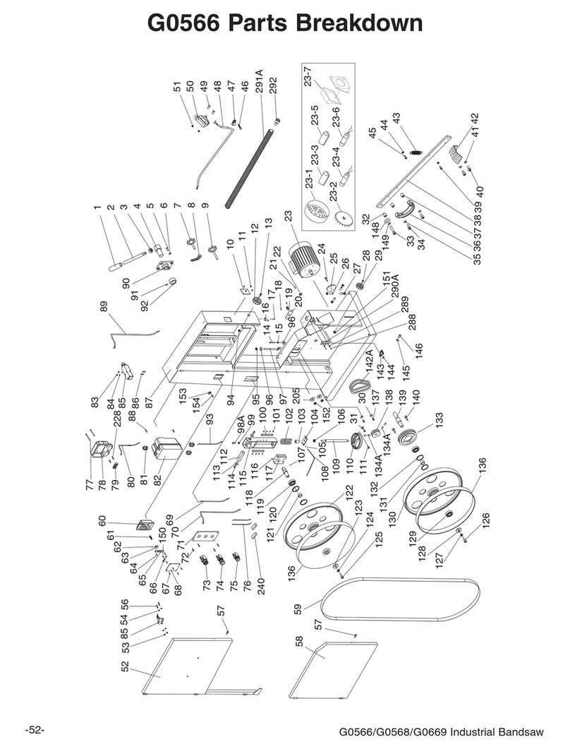
Main Breakdown

Model G0531B/G0566B-14-
REF PART # DESCRIPTION REF PART # DESCRIPTION
1 P0566001 HANDLE KNOB M16-1.5 36 PSS04M SET SCREW M6-1 X 12
2 P0566002 HANDLE SHAFT 37 P0566037 BUSHING
3 PN05M NUT M16-1.5 51 P0566290A SUPPORT
4 P0566004 ECCENTRIC SHAFT 52 P0566052 UPPER WHEEL COVER
5 PBHS25M BUTTON HD CAP SCR M10-1.5 X 20 53 PN04M HEX NUT M4-.7
6 PLW06M LOCK WASHER 10MM 54 PW05M FLAT WASHER 4MM
7 P0566007 KNOB SCREW M10-1.5 X 25 55 PLN03M LOCK NUT M6-1
8 P0566008 LOCK HANDLE M10-1.5 56 PS38M PHLP HD SCR M4-.7 X 10
9 P0566009 KNOB SCREW M10-1.5 X 25 57 PCAP04M CAP SCREW M6-1 X 10
10 P0566010 TRANSLUCENT PIECE 58 P0566058 LOWER WHEEL COVER
11 P0566011 RIVET 3.2 X 10 59 P0566059 SAW BLADE 4190 X 25.4 X 0.9MM
12 P0566012 LATCHING KNOB 6MM 60 P0566060 UPPER WHEEL SLIDING BRACKET
13 PCAP02M CAP SCREW M6-1 X 20 61 P0566061 SPRING
14 PB73M HEX BOLT M10-1.5 X 50 62 PRP61M ROLL PIN 3 X 12
15 PN02M HEX NUT M10-1.5 63 P0566063 MOVING PLATE
16 P0566016 HEIGHT POINTER 65 P0566065 FIX PLATE
17 PFS07M FLANGE SCREW M5-.8 X 10 66 P0566066 TENSION POINTER
18 PHTEK4M TAP SCREW M4 X 8 67 PHTEK6M TAP SCREW M4 X 16
19 P0566019 STRAIN RELIEF M20 68 P0566068 TENSION SCALE
20 P0566020 PLATE 69 P0566069 CONNECTING CORD
21 P0566B021 STEP COVER 70 P0566070 SWITCH CORD
22 PW01M FLAT WASHER 8MM 71 P0566071 SWITCH PLATE
23 P0531B023 MOTOR W/BRAKE 5HP 220V 1-PH (G0531B) 73 P0566073 KEY SWITCH 22MM
23 P0566B023 MOTOR W/BRAKE 3HP 220V 1-PH (G0566B) 74 P0566074 STOP SWITCH 22MM
23-2 P0531B023-2 MOTOR FAN COVER (G0531B) 75 P0566075 START SWITCH 22MM
23-2 P0566B023-2 MOTOR FAN COVER (G0566B) 76 PS52M PHLP HD SCR M4-.7 X 20
23-3 P0566B023-3 MOTOR FAN 77 PFS09M FLANGE SCREW M5-.8 X 50
23-4 P0566B023-4 R. CAPACITOR COVER 78 P0566078 TERMINAL BOX
23-5 P0566B023-5 S. CAPACITOR COVER 79 P0566079 TERMINAL BLOCK
23-6 P0531B023-6 R. CAPACITOR 45M 450V (G0531B) 80 P0531B080 MAG SWITCH SDE 22A MPE-18 (G0531B)
23-6 P0566B023-6 R. CAPACITOR 60M 400V (G0566B) 80 P0566B080 MAG SWITCH SDE 15A MPE-18 (G0566B)
23-7 P0531B023-7 S. CAPACITOR 300M 250V (G0531B) 80-1 P0566B080-1 MAG SWITCH BACK COVER
23-7 P0566B023-7 S. CAPACITOR 200M 250V (G0566B) 80-2 P0566B080-2 CONTACTOR SDE MA-18 220V
23-8 P0566B023-8 JUNCTION BOX 80-3 P0531B080-3 RELAY SDE RA-20 18-26A (G0531B)
23-9 P0566B023-10 CONTACT PLATE 80-3 P0566B080-3 RELAY SDE RA-20 12-18A (G0566B)
23-10 P0566B023-10 CENTRIFUGAL SWITCH 80-4 P0566B080-4 MAG SWITCH FRONT COVER
23-11 P0566B023-11 MAGNETIC BRAKE W/SHOE 80-5 P0513X2B019-5 POWER CORD 14G 3W
23-12 P0566B023-11 BRAKE SHOE 80-6 P0513X2B019-6 CORD 0.75MM X 5
23-13 PCAP26M CAP SCREW M6-1 X 12 80-7 P0513X2B019-7 MOTOR CORD 14G 5W
23-14 PLW03M LOCK WASHER 6MM 80-8 PFS07M FLANGE SCREW M5-.8 X 10
23-15 PK23M KEY 5 X 5 X 25 80-9 P0513X2B019-9 RECTIFIER (PU-23-2)
23-16 PCAP24M CAP SCREW M5-.8 X 16 85 P0566085 DOOR LATCH SWITCH ADZ-S11
23-17 PSS02M SET SCREW M6-1 X 6 85-1 P0566B085-1 DOOR LATCH SWITCH PLATE
24 PBHS23M BUTTON HD CAP SCR M8-1.25 X 25 87 P0566B087 MACHINE BODY
25 P0566025 COVER 89 P0566089 SWITCH CORD
26 PB14M HEX BOLT M10-1.5 X 35 90 P0566090 GUIDE BLOCK
27 P0566B027 ADJUST BOLT 91 P0566092 CAM
28 PW04M FLAT WASHER 10MM 92 PCAP31M CAP SCREW M8-1.25 X 25
29 PLW04M LOCK WASHER 8MM 95 P0566B095 CORD CLAMP 1/2"
30 PW01M FLAT WASHER 8MM 96 P0566B096 CORD CLAMP 5/16"
31 PCAP31M CAP SCREW M8-1.25 X 25 97 P0566B097 CORD CLAMP 3/8"
32 P0566B032 BRUSH 98 PCAP05M CAP SCREW M8-1.25 X 50
33 PW03M FLAT WASHER 6MM 99 PN03M HEX NUT M8-1.25
34 PCAP06M CAP SCREW M6-1 X 25 100 P0566100 LOCATE PLATE
35 PVA30 V-BELT A-30 4L300
Main Parts List

Model G0531B/G0566B -15-

Model G0531B/G0566B-16-
Table-Fence-Trunnion Breakdown
94 149
148
130
140
138
139
123
141
147
56
121
132
131
122
144
135
136
145
146 150
142
143-1
143-12
143-10
143-11
143-14
143-15
143-16
143-17
143-18
143-13
143-2
143-3
143-4
143-5
143-6
143-7
143-8 143-9
123-1
123-10
123-11
123-12
123-13
123-14
123-15
123-2
123-3
123-4
123-5
123-6
123-7
123-8
123-9
144-2
144-3
144-1
143
137
130
131
132
134
133
133-1
133-2
133-3
133-4
133-5
133-6

Model G0531B/G0566B -17-
Table-Fence-Trunnion Parts List
REF PART # DESCRIPTION REF PART # DESCRIPTION
56 PS38M PHLP HD SCR M4-.7 X 10 139 PSW03-1 KNOB
94 P0566B094 KNOB M8-1.25 X 20 140 PN09M HEX NUT M12-1.75
121 P0566B121 TABLE 141 P0566B141 POINTER
122 T24387 TABLE INSERT-G0566B AND G0531B 142 P0513X2B162 INNER RAIL PLATE
123 P0513X152 MITER GAUGE ASSY 143 P0513X2B157 FENCE ASSSMBLY
123-1 P0513X152 GUIDE BAR 143-1 P0513X2B157-1 FENCE
123-2 P0513X2B152-2 GUIDE PIECE 143-2 P0513X2B157-2 POINTER
123-3 PFH04M FLAT HD SCR M6-1 X 8 143-3 PSS09M SET SCREW M8-1.25 X 20
123-4 P0513X152 POINTER 143-4 P0513X2B157-4 SPRING PIECE
123-5 PS06 PHLP HD SCR 10-24 X 3/8 143-5 PFS17M FLANGE SCREW M4-.7 X 8
123-6 P0513X2B152-6 SHOULDER SCREW 143-6 P0513X2B157-6 PIVOT BLOCK
123-7 P0513X152 MITER GAUGE BODY 143-7 PN03M HEX NUT M8-1.25
123-8 PW01M FLAT WASHER 8MM 143-8 P0513X2B157-8 HANDLE
123-9 P0513X152 HANDLE 143-9 P0513X2B157-9 SHAFT
123-10 P0513X152 FIXED BLOCK 143-10 P0513X2B157-10 FENCE PLASTIC SET SCREW
123-11 P0513X152 LOCKING SHAFT 143-11 P0513X2B157-11 NYLON PAD
123-12 PS06 PHLP HD SCR 10-24 X 3/8 143-12 PSS14M SET SCREW M8-1.25 X 12
123-13 PN04M HEX NUT M4-.7 143-13 PN03M HEX NUT M8-1.25
123-14 PS56M PHLP HD SCR M4-.7 X 16 143-14 PB30M HEX BOLT M8-1.25 X 55
123-15 P0513X2B152-15 SCALE 143-15 PN03M HEX NUT M8-1.25
130 PCAP84M CAP SCREW M10-1.5 X 35 143-16 PW01M FLAT WASHER 8MM
131 PLW06M LOCK WASHER 10MM 143-17 P0513X2B157-17 LOCK HANDLE M8-1.25 X 44
132 PW04M FLAT WASHER 10MM 143-18 P0513X2B157-18 MOVING PLATE
133 P0566B133 TRUNNION BRACKET ASSY 144 P0513X2B156 RESAW FENCE ASSEMBLY
133-1 P0566168 PRESS SHAFT 144-1 P0513X2B156-1 RESAW FENCE ALUMINUM 590MM
133-2 P0566169 MICRO ADJUSTING RING 144-2 P0636X122 TAP SCREW 3.5 X 8
133-3 PCAP14M CAP SCREW M8-1.25 X 20 144-3 P0513X2B156-3 FENCE PIECE 148 X 22 X 1
133-4 PLW04M LOCK WASHER 8MM 145 PLW03M LOCK WASHER 6MM
133-5 P0566177 TRUNNION BLOCK 146 PCAP02M CAP SCREW M6-1 X 20
133-6 P0566178 PRESS BLOCK 147 P0566B147 GUARD RAIL
135 P0513X2B154 OUTER RAIL PLATE 148 PW01M FLAT WASHER 8MM
136 PW03M FLAT WASHER 6MM 149 PLW04M LOCK WASHER 8MM
137 PFB09M FLANGE BOLT M6-1 X 10 150 PCAP14M CAP SCREW M8-1.25 X 20
138 P0566172 HANDLE SHAFT

Model G0531B/G0566B-18-
171
170
163
164
148
165
148
167
156
166
149
166
158
157
152
152-1
152-2
152-3
152-4
152-5
152-6
152-21
152-7
152-8
152-9
152-10 152-11
152-12
152-13
152-16
152-22
152-17
152-18
152-19
152-20
152-15
152-14
153
153-1
153-2
153-3
153-3
153-4
153-5
153-6
153-7
153-8
153-9
153-10
153-11
153-12
153-13
158
156
161
162
137
160
156
158
158
159
157
15655
111
53
56
151
151-1
151-2
151-3
151-4
151-5
151-6
151-6
151-7
151-8
151-9
151-10
151-11
151-13
151-14
151-15
151-16
151-12
155
111
155
169
168
154
154-1
154-2
154-2
154-2
154-3
154-4
154-5
154-6
154-7
154-8
154-9
154-10
154-11
154-12
Guides Breakdown

Model G0531B/G0566B -19-
REF PART # DESCRIPTION REF PART # DESCRIPTION
53 PN04M HEX NUT M4-.7 152-22 P0566B152-22 FIXED BOLT
55 PLN03M LOCK NUT M6-1 153 P0566B153 UPPER BLADE GUIDE ASSEMBLY
56 PS38M PHLP HD SCR M4-.7 X 10 153-1 P0566259A ADJUST BAR
111 PCAP06M CAP SCREW M6-1 X 25 153-2 P0566260A BLADE GUIDE SUPPORT
137 PFB09M FLANGE BOLT M6-1 X 10 153-3 PB04M HEX BOLT M6-1 X 10
148 PW01M FLAT WASHER 8MM 153-4 P0566262A UPPER SPACING SLEEVE
149 PLW04M LOCK WASHER 8MM 153-5 P6201ZZ BALL BEARING 6201ZZ
151 P0566B151 LOWER GUIDE BRACKET ASSEMBLY 153-6 PR03M EXT RETAINING RING 12MM
151-1 P0566225 WORM CYLINDER 153-7 PCAP29M CAP SCREW M6-1 X 40
151-2 PN05M HEX NUT M16-1.5 153-8 P0566274 HANDLE BUSHING
151-3 P0566230 BUSHING 153-9 P6202ZZ BALL BEARING 6202ZZ
151-4 P0566231 SWITCH BUSHING 153-10 PR05M EXT RETAINING RING 15MM
151-5 PSS07M SET SCREW M5-.8 X 5 153-11 P0566277A ECCENTRIC SHAFT
151-6 PLW04M LOCK WASHER 8MM 153-12 PB04M HEX BOLT M6-1 X 10
151-7 PCAP11M CAP SCREW M8-1.25 X 16 153-13 P0566211A UPPER GUIDE SUPPORT BLOCK
151-8 PFS07M FLANGE SCREW M5-.8 X 10 154 P0566155 FENCE
151-9 P0566187 COVER 154-1 P0566260A BLADE GUIDE SUPPORT
151-10 P0566238 LOWER GUIDE BRACKET COVER 154-2 PCAP04M CAP SCREW M6-1 X 10
151-11 P0566239 PINION BOLT 154-3 P0566262A UPPER SPACING SLEEVE
151-12 P0566246 PINION GEAR 154-4 P6201ZZ BALL BEARING 6201ZZ
151-13 PFH19M FLAT HD SCR M4-.7 X 10 154-5 PR03M EXT RETAINING RING 12MM
151-14 P0566242 LOWER GUIDE RACK 154-6 P0566267A ADJUSTING SHAFT
151-15 P0566243 SQUARE TUBE 154-7 PB47M HEX BOLT M6-1 X 40
151-16 P0566213 GUIDE BRACKET 154-8 P0566274 HANDLE BUSHING
152 P0566B152 UPPER GUIDE ASSY 154-9 P6202ZZ BALL BEARING 6202ZZ
152-1 PN06M HEX NUT M5-.8 154-10 PR05M EXT RETAINING RING 15MM
152-2 PFS07M FLANGE SCREW M5-.8 X 10 154-11 P0566277A ECCENTRIC SHAFT
152-3 P0566187 COVER 154-12 P0566279A SUPPORT BRACKET
152-4 PLW04M LOCK WASHER 8MM 155 P0566204 HANDWHEEL
152-5 PCAP11M CAP SCREW M8-1.25 X 16 156 PCAP04M CAP SCREW M6-1 X 10
152-6 PFH19M FLAT HD SCR M4-.7 X 10 157 PLW03M LOCK WASHER 6MM
152-7 P0566192 COVER 158 PW03M FLAT WASHER 6MM
152-8 P0566195 FIXED PLATE 159 P0566250 SUPPORT PLATE
152-9 P0566196 WORM CYLINDER 160 P0566B160 PROTECT COVER ASSEMBLY
152-10 PN05M HEX NUT M16-1.5 161 P0566B161 SLIDING PLATE
152-11 P0566198 GUIDE BRACKET 162 P0566B162 FIBER WASHER
152-12 P0566201 BUSHING 163 PB30M HEX BOLT M8-1.25 X 55
152-13 P0566202 SWITCH BUSHING 164 P0566B164 SLIDING PLATE
152-14 PSS07M SET SCREW M5-.8 X 5 165 PLN04M LOCK NUT M8-1.25
152-15 P0566194 PINION GEAR 166 PCAP14M CAP SCREW M8-1.25 X 20
152-16 P0566206 UPPER GUIDE BAR 167 P0566B167 SUPPORT PLATE
152-17 P0566207 UPPER GUIDE RACK 168 PW03M FLAT WASHER 6MM
152-18 PCAP01M CAP SCREW M6-1 X 16 169 PCAP26M CAP SCREW M6-1 X 12
152-19 PN04M HEX NUT M4-.7 170 PCAP40M CAP SCREW M8-1.25 X 35
152-20 PS38M PHLP HD SCR M4-.7 X 10 171 PW01M FLAT WASHER 8MM
152-21 P0566191 EXTENSION RACK
Guides Parts List

Model G0531B/G0566B-20-
Labels Breakdown
207
218
215
201
202
203
204
216
205
206
207
220 208
210
211
212
213
214
REF PART # DESCRIPTION REF PART # DESCRIPTION
201 P0531B201 MODEL NUMBER LABEL (G0531B) 211 P0513X210 EXTREME SERIES PLATE
201 P0566B201 MODEL NUMBER LABEL (G0566B) 212 PPAINT-11 GREY PUTTY PAINT
202 G8589 GRIZZLY LOGO PLATE 213 PLABEL-18 DISCONNECT POWER LABEL
203 PLABEL-11 SAFETY GLASSES LABEL 214 PLABEL-20 OPEN DOOR LABEL
204 PLABEL-20 OPEN DOOR LABEL 215 P0513X214 TENSION ADJ LABEL
205 P0513X204 GUARD ADJ LABEL 216 P0531B216 MACHINE ID LABEL (G0531B)
206 PLABEL-12 READ MANUAL LABEL 216 P0566B216 MACHINE ID LABEL (G0566B)
207 PLABEL-14 ELECTRICITY LABEL 218 P0566301 TABLE LOCK LABEL
208 PLABEL-19 HANDS/BLADE LABEL 220 P0566B220 MAGNETIC BRAKE NOTICE
210 PPAINT-1 GRIZZLY GREEN PAINT
Safety labels warn about machine hazards and ways to prevent injury. The owner of this machine
MUST maintain the original location and readability of the labels on the machine. If any label is
removed or becomes unreadable, REPLACE that label before using the machine again. Contact
Grizzly at (800) 523-4777 or www.grizzly.com to order new labels.
This manual suits for next models
1
Table of contents
Other Grizzly Saw manuals

Grizzly
Grizzly G0715P User manual

Grizzly
Grizzly G0555 User manual

Grizzly
Grizzly G0651 User manual

Grizzly
Grizzly g0531b User manual

Grizzly
Grizzly G0736 User manual

Grizzly
Grizzly G0561 User manual

Grizzly
Grizzly G0967X User manual

Grizzly
Grizzly T10687 User manual

Grizzly
Grizzly G0513 SERIES User manual

Grizzly
Grizzly G0504 User manual

Grizzly
Grizzly H3118 User manual

Grizzly
Grizzly G0614 User manual

Grizzly
Grizzly G4030 User manual

Grizzly
Grizzly G0502 User manual

Grizzly
Grizzly Extreme Series User manual

Grizzly
Grizzly G0560 User manual

Grizzly
Grizzly T28360 User manual

Grizzly
Grizzly G1022PRO User manual

Grizzly
Grizzly G0803Z User manual

Grizzly
Grizzly G0764 User manual