Groen DH-20 User manual

This manual provides information for:
OPERATOR MANUAL
IMPORTANT INFORMATION, KEEP FOR OPERATOR
PART NUMBER 174845, REV. C (07/17)
MODEL
DH/DHT
MODEL DH(T)-20, -40, -60, -80,
MODEL DH(T)-20(C,A), MODEL DH(T)-40(C,A)
MODEL DH(T)-60(C,A), MODEL DH(T)-80(C,A) DOMESTIC
STEAM JACKETED KETTLE
With Standard Electronic Ignition
· Self-Contained
· Floor Mounted
· Gas Heated
· Tilting
THIS MANUAL MUST BE RETAINED FOR FUTURE REFERENCE.
READ, UNDERSTAND AND FOLLOW THE INSTRUCTIONS AND
WARNINGS CONTAINED IN THIS MANUAL.
FOR YOUR SAFETY
Do not store or use gasoline or other ammable vapors
and liquids in the vicinity of this or any other appliance.
POST IN A PROMINENT LOCATION
Instructions to be followed in the event user smells gas.
This information shall be obtained by consulting your
local gas supplier. As a minimum, turn o the gas and
call your gas company and your authorized service agent.
Evacuate all personnel from the area.
WARNING
Improper installation, adjustment, alteration, service
or maintenance can cause property damage, injury or
death. Read the installation, operating and maintenance
instructions thoroughly before installing or servicing this
equipment.
NOTIFY CARRIER OF DAMAGE AT ONCE
It is the responsibility of the consignee to inspect the container upon receipt of
same and to determine the possibility of any damage, including concealed dam-
age. Unied Brands suggests that if you are suspicious of damage to make a
notation on the delivery receipt. It will be the responsibility of the consignee to le
a claim with the carrier. We recommend that you do so at once.
Manufacture Service/Questions 888-994-7636.
Information contained in this document is known to be current and accurate at the time
of printing/creation. Unified Brands recommends referencing our product line websites,
unifiedbrands.net, for the most updated product information and specifications.
1055 Mendell Davis Drive
Jackson, MS 39272
888-994-7636, fax 888-864-7636
unifiedbrands.net

2 OM-DH/DHT
IMPORTANT - READ FIRST - IMPORTANT
CAUTION: BE SURE ALL OPERATORS READ, UNDERSTAND AND FOLLOW THE OPERATING INSTRUCTIONS, CAUTIONS, AND SAFETYINSTRUCTIONS
CONTAINED IN THIS MANUAL.
WARNING: THIS UNIT IS INTENDED FOR USE IN THE COMMERCIAL HEATING, COOKING AND HOLDING OF WATER AND FOOD PRODUCTS, PER THE
INSTRUCTIONS CONTAINED IN THIS MANUAL. ANY OTHER USE COULD RESULT IN SERIOUS PERSONAL INJURY OR DAMAGE TO THE
EQUIPMENT AND WILL VOID WARRANTY.
WARNING: KETTLE MUST BE INSTALLED BY PERSONNEL QUALIFIED TO WORK WITH ELECTRICITY AND PLUMBING. IMPROPER INSTALLATION CAN
RESULT IN INJURY TO PERSONNEL AND/OR DAMAGE TO EQUIPMENT.
DANGER: ELECTRICALLY GROUND THE UNIT AT THE TERMINAL PROVIDED. FAILURE TO GROUND UNIT COULD RESULT IN ELECTROCUTION AND
DEATH.
WARNING: DO NOT CONNECT ANY PIPING TO THE POP SAFETY VALVE. THE VALVE MUST BE FREE TO VENT STEAM AS NEEDED. THE ELBOW
ATTACHED TO THE SAFETY VALVE SHOULD POINT TO THE FLOOR. IMPROPER INSTALLATION WILL VOID WARRANTY.
WARNING: AVOID ALL DIRECT CONTACT WITH HOT EQUIPMENT SURFACES. DIRECT SKIN CONTACT COULD RESULT IN SEVERE BURNS.
WARNING: AVOID ALL DIRECT CONTACT WITH HOT FOOD OR WATER IN THE KETTLE. DIRECT CONTACT COULD RESULT IN SEVERE BURNS.
CAUTION: DO NOT OVER FILL THE KETTLE WHEN COOKING, HOLDING OR CLEANING. KEEP LIQUIDS A MINIMUM OF 2-3” (5-8 CM) BELOW THE
KETTLE BODY RIM TO ALLOW CLEARANCE FOR STIRRING, BOILING AND SAFE PRODUCT TRANSFER.
WARNING: TAKE SPECIAL CARE TO AVOID CONTACT WITH HOT KETTLE BODY OR HOT PRODUCT WHEN ADDING INGREDIENTS, STIRRING OR
TRANSFERRING PRODUCT TO ANOTHER CONTAINER.
WARNING: WHEN TILTING KETTLE FOR PRODUCT TRANSFER:
1) USE CONTAINER DEEP ENOUGH TO CONTAIN AND MINIMIZE SPLASHING.
2) PLACE CONTAINER ON STABLE, FLAT SURFACE, AS CLOSE TO KETTLE AS POSSIBLE.
3) DO NOT OVER FILL CONTAINER. AVOID DIRECT SKIN CONTACT WITH HOT CONTAINER AND ITS CONTENTS.
CAUTION: KEEP FLOORS IN FRONT OF KETTLE WORK AREA CLEAN AND DRY. IF SPILLS OCCUR, CLEAN IMMEDIATELY, TO AVOID SLIPS OR FALLS.
WARNING: FAILURE TO CHECK SAFETY VALVE OPERATION PERIODICALLY COULD RESULT IN PERSONAL INJURY AND/OR DAMAGE TO EQUIPMENT.
WARNING: WHEN TESTING SAFETY VALVE, AVOID ANY EXPOSURE TO THE STEAM BLOWING OUT OF THE SAFETY VALVE. DIRECT CONTACT WITH
STEAM COULD RESULT IN SEVERE BURNS.
WARNING: TO AVOID INJURY, READ AND FOLLOW ALL PRECAUTIONS STATED ON THE LABEL OF THE WATER TREATMENT COMPOUND.
WARNING: BEFORE REPLACING ANY PARTS, DISCONNECT THE UNIT FROM THE ELECTRIC POWER SUPPLY AND CLOSE THE MAIN GAS VALVE.
ALLOW FIVE MINUTES FOR UNBURNED GAS TO VENT.
WARNING: KEEP WATER AND SOLUTIONS OUT OF CONTROLS AND ELECTRICAL EQUIPMENT. NEVER SPRAY OR HOSE THE SUPPORT HOUSING OR
ELECTRICAL CONNECTIONS.
CAUTION: MOST CLEANERS ARE HARMFUL TO THE SKIN, EYES, MUCOUS MEMBRANES AND CLOTHING. PRECAUTIONS SHOULD BE TAKEN. WEAR
RUBBER GLOVES, GOGGLES OR FACE SHIELD AND PROTECTIVE CLOTHING. CAREFULLY READ THE WARNINGS AND FOLLOW THE
DIRECTIONS ON THE LABEL OF THE CLEANER TO BE USED.
CAUTION: USE OF ANY REPLACEMENT PARTS OTHER THAN THOSE SUPPLIED BY GROEN OR THEIR AUTHORIZED SERVICE AGENTS CAN CAUSE
OPERATOR INJURY AND DAMAGE TO THE EQUIPMENT, AND WILL VOID ALL WARRANTIES.
IMPORTANT: SERVICE PERFORMED BY OTHER THAN FACTORY AUTHORIZED PERSONNEL WILL VOID WARRANTIES.
WARNING: DO NOT HEAT AN EMPTY KETTLE. EXCESSIVE STEAM PRESSURE COULD DEVELOP.

OM-DH/DHT 3
Important Operator Warnings ...........................................................page 2
References.................................................................................... page 3
Equipment Description................................................................... page 4
Inspection and Unpacking ............................................................ page 5
Installation .................................................................................. page 6-7
Initial Start-Up................................................................................ page 8
Operation ................................................................................ page 9-12
Sequence of Operation ................................................................ page 13
Cleaning........................................................................................ page 14
Maintenance........................................................................... page 15-17
Troubleshooting..................................................................... page 18-19
Parts List................................................................................ page 20-30
Wiring Diagram .................................................................... page 31-32
Service Log .................................................................................. page 33
CSA INTERNATIONAL
8501 East Pleasant Valley Road
Cleveland, Ohio 44131
NATIONAL SANITATION FOUNDATION
3475 Plymouth Road
Ann Arbor, Michigan 48106
KLENZADE SALES CENTER ECOLAB, Inc.
370 Wabasha
St. Paul, Minnesota 55102
ZEP MANUFACTURING COMPANY
1310-T Seaboard Industrial Boulevard
Atlanta, Georgia 30318
AMERICAN NATIONAL STANDARDS INST., Inc.
1430 Broadway
New York, New York 10018
Z223.1-1984 - National Fuel Gas Code
Z21.30 - Installation Gas Appliances & Piping
NATIONAL FIRE PROTECTION ASSOCIATION
60 Battery march Park
Quincy, Massachusetts 02269
NFPA/54 -Installation Gas Appliances & Piping
NFPA/70 - The National Electric Code
Table of Contents
References

4 OM-DH/DHT
The Groen DH is a floor-mounted, tilting, steam jacketed kettle with a thermostatically or
electronically controlled, self-contained, gas-heated steam source and appropriate controls,
mounted on a sturdy base. The Model DH is available in 20, 40, 60 or 80 gallon capacities.
The body of the DH Kettle is constructed of stainless steel, welded into one solid piece.
The kettle is furnished with a reinforced rim and a butterfly shaped pouring lip. It has a
steam jacket which is ASME shop inspected and registered with the national board for
working pressures up to 50 PSI. Kettle finish is 180 emery grit on the inside and bright
high buff polish on the outside.
The kettle is tilted with a hand crank to pour out its contents. Stainless steel panels
enclose the controls and the base. Four stainless steel tubular legs support the unit.
Bullet or flanged feet on each of the legs can be adjusted to level the kettle. Standard
DHT units include a two inch tangent draw-off valve.
The self-contained steam source is heated by propane or natural gas. Ignition is
electronic.
The kettle is charged at the factory with chemically pure water which contains rust
inhibitors. The steam source provides kettle temperatures of 150º to approximately
295ºF (65 to 150ºC). Unit controls include a thermostat or controller, pressure gauge,
safety valve, pressure limit control, low water cut-off, power switch and gas regulator
valve. The gas supply shuts off automatically when the kettle is tilted.
The unit must be specified for use with natural or propane gas. Service connections for
gas and electricity are required. Standard power supply is 115 Volt. Alternate single-
phase voltages (208-240V) are available.
Available Options:
1. Two inch tangent drawoff standard on DHT models
2. Strainers, solid disk, 1/4 or 1/8 inch holes
3. No. 31 lift-off cover
4. No. 51 counterbalanced cover w/actuator*
5. Basket Inserts (Tri-BC)
6. Water fill faucets with swing spout
7. Kettle Brush Kit
Equipment Description
KETTLE CHARACTERISTICS
DH/DHT-20 DH/DHT-40 DH/DHT-60 DH/DHT-80
Kettle
Capacity
20 gal.
(75 ltr)
40 gal.
(150 ltr)
60 gal.
(225 ltr)
80 gal.
(302 ltr)
Kettle Body Diameter 20 in.
(508 mm)
26 in.
(660 mcm)
30 in.
(762 mm)
34 in.
(863 mm)
Base Width 35 in.
(889 mm)
47 in.
(1194 mm)
47 in.
(1194 mm)
52 in.
(1320 mm)
Base Front to Back 29 in.
(736 mm)
29 in.
(736 mm)
29 in.
(736 mm)
37.5 in.
(952 mm)
Firing Rater Per Hour 72,000 BTU 100,000 BTU 150,000 BTU 150,000 BTU
Energy into Product
Per Hour 44,140 BTU 65,000 BTU 93,000 BTU 93,000 BTU

OM-DH/DHT 5
Inspection & Unpacking
CAUTION
SHIPPING STRAPS ARE UNDER TENSION
AND CAN SNAP BACK WHEN CUT. TAKE
CARE TO AVOID PERSONAL INJURY OR
DAMAGE TO THE UNIT BY STAPLES LEFT
IN THE WALLS OF THE CARTON.
The unit will arrive in a heavy shipping carton and will be bolted or banded to a skid.
Immediately upon receipt, inspect the carton carefully for exterior damage. Carefully cut
any polyester straps around the carton and detach the sides of the box from the skid.
Pull the carton up off the unit. Thoroughly inspect the unit for hidden damage. Report any
shipping damage or incorrect shipments to the delivery agent.
Write down the model number, serial number, and installation date, and retain this
information for future reference. Space for these entries is provided at the top of the Service
Log at the back of this manual. Keep this manual on file and available for operators to use.
When installation is to begin, carefully cut any straps which hold the unit on the skid. Lift
the unit straight up off the skid. Examine packing materials to be sure loose parts are not
discarded with the materials.
CAUTION
THIS UNIT WEIGHS BETWEEN 535 AND
978 POUNDS (245 TO 400 Kg) DEPENDING
ON SIZE. INSTALLER SHOULD USE
PROPER EQUIPMENT TO LIFT SAFELY.

6 OM-DH/DHT
For efficient performance the DH kettle must be installed in a well-ventilated area. Items
which might restrict or obstruct the flow of air for combustion and ventilation must be
removed. The area directly around the appliance must be free of combustible materials.
1. Installation can be on a combustible or noncombustible floor. Clearences should be
per table below.
DANGER
ELECTRICALLY GROUND THE UNIT AT
THE TERMINAL PROVIDED. FAILURE
TO GROUND UNIT COULD RESULT IN
ELECTROCUTION AND DEATH.
Installation
WARNING
THE UNIT MUST BE INSTALLED BY
PERSONNEL WHO ARE QUALIFIED TO WORK
WITH GAS, ELECTRICITY AND PLUMBING.
IMPROPER INSTALLATION CAN CAUSE
INJURY TO PERSONNEL AND/OR DAMAGE
TO THE EQUIPMENT. THE UNIT MUST
BE INSTALLED IN ACCORDANCE WITH
APPLICABLE CODES. THE UNIT MUST BE
INSTALLED BY A LICENSED PLUMBER OR
GAS FITTER WHEN INSTALLED WITHIN THE
COMMONWEALTH OF MASSACHUSETTS.
Minimum Clearance
from Combustible walls
Minimum Clearance from
Non-Combustible walls
Recommended
Clearances
Left
Side 6 in. 0 in. 6 in.
Right
Side 6 in. 0 in. 10 in.
Rear 10 in. 10 in. 12 in.
2. The kettle should be installed in an adequately ventilated room with provision for
adequate air supply. The ventilation must employ a vent hood and exhaust fan with
no direct connection between the vent duct and the kettle flue. Do not obstruct the
flue or vent duct after installation.
3. Set the kettle in place and level it using a spirit level on the bar rim, by turning
the bullet or flange feet to adjust leg length. Allow clearance around the unit for
cleaning, maintenance and service.
4. Complete the piping to the gas service main with ½” line or approved equivalent.
5. Provide 115 vac, 60 Hz, single phase 5 AMP electrical service. The unit may also
be ordered for alternate electric service of 208 VAC - 240 VAC. Observe local codes
and/or The National Electrical Code in accordance with ANSI/NFPA 70 (current
edition), or the Canadian Electrical Code, CSA C22.2 (current edition), as applicable.
Use the wiring diagram inside the service panel and at the rear of this manual.
6. Bring electrical service through the entrance at the rear of the support housing
with a ½ inch conduit connector. Make a watertight connection with the incoming
lines.
7. Electrically ground the unit at the terminal provided.
8. After the kettle has been connected to the gas supply, check all gas joints for leaks.
DO NOT USE FLAME TO CHECK FOR LEAKS. A thick soap solution or other suitable
leak detector should be employed.
9. The gas supply and unit’s installation must conform with local codes or in the

OM-DH/DHT 7
Installation
absence of local codes, with the National Fuel Gas Code, ANSI Z223.1/NFPA
54 (current edition), or the Natural Gas and Propane Installation Code CSA
149.1(current edition), as applicable. Additionally following must be complied
with: THE AREA DIRECTLY AROUND THE APPLIANCE MUST BE CLEARED OF ALL
COMBUSTIBLE MATERIAL. FAILURE TO FOLLOW THESE INSTRUCTIONS CAN CAUSE
BODILY INJURY AND /OR PROPERTY DAMAGE. The appliance and its individual
shut-off valve must be disconnected from the gas supply piping system during any
testing at pressures in excess of ½ PSI (3.45 kPa). The appliance must be isolated
from the gas supply piping system by closing its individual manual shut-off valve
during any pressure testing at or less than ½ PSI (3.45 kPa).
10.Confirm that the jacket water level is between the gauge glass markers or inside
the sight glass port. If the level is low, follow instructions under “Jacket Filling and
Water Treatment,” Page 16.
11.The open end of the elbow on the outlet of the safety valve must face downward. If
it does not, turn it to the correct position.
12.For units with optional tangent drawoff: Assemble the tangent draw-off by placing
the large nut over the draw-off valve and inserting it into the draw-off tube. ONLY
HAND-TIGHTEN THE NUT to complete installation.
WARNING
DO NOT CONNECT ANY PIPING TO THE
PRESSURE RELIEF VALVE. THE VALVE MUST
BE FREE TO VENT STEAM AS NEEDED.
IMPROPER INSTALLATION WILL VOID THE
WARRANTY! THE ELBOW ATTACHED TO
THE PRESSURE RELIEF VALVE MUST
POINT TO THE FLOOR.
The open end of the pressure
relief valve elbow must face downward
When attaching the draw-off
valve, hand-tighten the nut

8 OM-DH/DHT
Initial Start-Up
Now that the kettle has been installed, you should test it to ensure that the unit is
operating correctly.
1. Remove literature and packing materials from the interior and exterior of the unit.
2. If the unit is equipped with a draw-off valve (product outlet), clean out any material
which might clog or damage the draw-off.
3. Confirm that the tilting mechanism is operating properly by tilting the kettle
through its full range. Then return the kettle to the upright position.
4. Turn on the electrical service to the unit.
5. Pour 1-2 gallons of water into the kettle.
6. Following “To Start Kettle” instructions in the “Operation” section (page 10), begin
heating the water at the highest controller setting. The heat indicator light should
come on, and heating should continue until the water boils.
If the unit functions as described above, it is ready for use. If it does not, contact your
local Authorized Service Agency.
WARNING
WATER IS EXTREMELY HOT AND CAN CAUSE
SEVERE BURNS. AVOID CONTACT WITH HOT
WATER WHEN EMPTYING UNIT.
WARNING
DO NOT STAND ON OR APPLY UNNECESSARY
WEIGHT OR PRESSURE ON THE KETTLE
FRONT OR POURING LIP. THIS COULD RESULT
IN THE OVERLOAD AND FAILURE OF THE
TILT MECHANISM, AND POSSIBLE
SERIOUS INJURY AND BURNS TO
THE OPERATOR AND OTHERS.
Correct water level
(Model DH-80E and DHT-80 only)
Each day confirm the jacket water
level by checking the water gauge.

OM-DH/DHT 9
Operation
MODELS DH(T)-20, -40, -60, -80
A. Controls
1. The “Classic” Controls for the kettle are:
a. The manual gas shut-off valve supplies inlet gas to the unit.
b. Lighted Power ON switch located on the control console. Controls
main power to the unit.
c. The temperature knob, located on the control console, is used to set
the kettle heat values between 1 and 10.
d. Heating indicator light located on the control console, lights when
the controller sends call to open the main gas valve and will cycle on
and off once the unit reaches set temperature. If the unit is tilted, the
main gas valve will be disabled and the light will turn off until the unit
is returned to the cooking position.
e. A LOW WATER indicator light, located on the control console,
illuminates when the jacket water falls below acceptable levels.
When lit, the main gas valve is disabled and will not function until
the jacket water is refilled using the procedure on p. 16 of this
manual.
f. Crank tilt - a handle controls the worm and gear mechanism that
smoothly tilts the kettle body and holds it in the desired position.
2. The “Advanced” Controls for the kettle are:
a. The manual gas shut-off valve supplies inlet gas to the unit.
b. Lighted Power ON switch located on the control console. Controls
main power to the unit.
c. The temperature knob, located on the control console, is used to set
the kettle heat values between 1 and 10. The current setting will be
reflected on the display.
d. Heating indicator light located on the control console, lights when
the controller sends call to open the main gas valve and will cycle on
and off once the unit reaches set temperature. If the unit is tilted, the
main gas valve will be disabled and the light will turn off until the unit
is returned to the cooking position.
e. A LOW WATER indicator light, located on the control console,
illuminates when the jacket water falls below acceptable levels.
When lit, the main gas valve is disabled and will not function until
the jacket water is refilled using the procedure on p. 16 of this
manual.
f. SET TnnP Mode - Allows power to the controller and gas to the pilot
without the kettle heating; the kettle will heat once the LOW TEMP,
MANUAL or HIGH TEMP button is selected.
g. LOW TEMP Button – Used to set operating temperature of the kettle
at a preset low intensity (default = 2). Can be pressed at any time
during operation of the unit to change the set temperature to the
preset value except when there is an active TIMER enabled.
h. MANUAL Mode button – Enables the user modify the desired cooking
temperature of the kettle (between 1 and 10) using the temperature
knob and display (default = 4). The operator will press the MANUAL
button and set the desired temperature using the temperature knob
and display. Once the desired intensity is displayed, the user may
either press the MANUAL button again or wait 5 seconds and the set
temperature will be accepted by the controller and locked in. After
Classic Control
Advanced Control

10 OM-DH/DHT
Operation
WARNING
WHEN TILTING KETTLE:
1) WEAR PROTECTIVE OVEN MITT AND
PROTECTIVE APRON.
2) USE DEEP CONTAINER TO CONTAIN
AND MINIMIZE PRODUCT SPLASHING.
3) PLACE CONTAINER ON STABLE,
FLAT SURFACE, AS CLOSE TO
KETTLE AS POSSIBLE.
4) STAND TO RIGHT OF KETTLE WHILE
POURING — NOT DIRECTLY IN POUR
PATH OF HOT CONTENTS.
5) POUR SLOWLY, MAINTAINING
CONTROL OF KETTLE, AND RETURN
KETTLE BODY TO UPRIGHT POSITION
AFTER CONTAINER IS FILLED OR
TRANSFER IS COMPLETE.
6) DO NOT OVERFILL CONTAINER.
AVOID SKIN CONTACT WITH HOT
CONTAINER AND ITS CONTENTS.
WARNING
AVOID ALL DIRECT CONTACT WITH HOT
SURFACES AND HOT FOOD OR WATER
IN THE KETTLE. DIRECT CONTACT
COULD RESULT IN SEVERE BURNS.
CAUTION
DO NOT TILT KETTLE WITH LIFT-OFF
COVER IN PLACE. COVER MAY SLIDE
OFF, CAUSING INJURY TO OPERATOR.
the set temperature is accepted, it may be changed at any time by
pressing the MANUAL button and resetting the temperature using the
same process above.
i. HIGH TEMP button – Used to set operating temperature of the kettle
at a preset high intensity (default = 7). Can be pressed at any time
during operation of the unit to change the set temperature to the
preset value except when there is an active TIMER enabled.
1. TIMER button - once the appropriate set temperature is
selected using the HIGH TEMP, MANUAL or LOW TEMP buttons;
a countdown timer can be set to remind the user when the
cooking process is completed. Range – 1 minute to 10 hours
2. When the timer expires:
a. the set temperature will automatically change to the LOW
TEMP setting and will continue at this setting until the
user changes the temperature via MANUAL or HIGH TEMP
buttons
b. An audible alarm will notify the user that attention is
required, the alarm will continue to sound until the user
presses the TIMER button.
3. An active timer can be cancelled by pressing and holding the
TIMER button for 5 secs
4. Set temp can be changed during an active timer by pressing
the MANUAL button and adjusting the set temp using the
Temperature knob and display
5. HIGH TEMP and LOW TEMP presets cannot be used to change
the setpoint once a TIMER has started.
j. READY alarm – The control will sound 3 beeps when the unit has
reached within 20 degrees of set point during pre-heat and when a
higher set temperature is selected.
k. Crank tilt - a handle controls the worm and gear mechanism that
smoothly tilts the kettle body and holds it in the desired position.
B. Operating Procedure
1. To Start Kettle Heating:
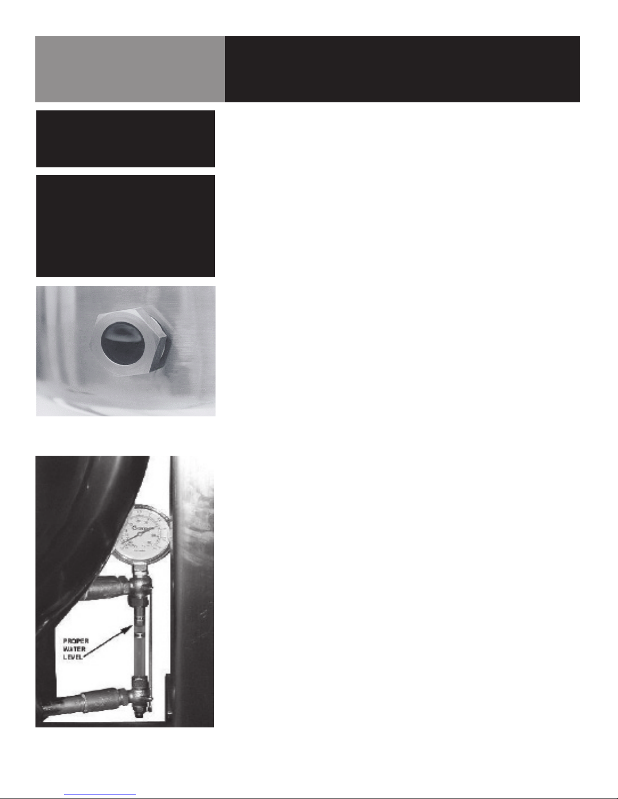
a. EVERY DAY make sure that the jacket water level in the middle of
the sight glass. If the level is too low, see “Jacket Filling and Water
Treatment” on page 16.
b. Check the pressure/vacuum gauge. If the gauge does not show 20
to 30 inches of mercury (Hg) vacuum (that is a reading of 20 to 30
below 0 atmospheric pressure), see “Jacket Vacuum” on page 16.
c. Do not attempt to light any burner with a flame.
d. Turn the manual gas valve ON (align handle with gas line).
e. Turn rocker (on-off) switch ON. The electronic ignition will attempt to
light the pilot for 90 seconds, or until it is lit. Once lit proceed to step
two.
f. Turn controller to desired setting. The main gas burner will ignite, and
will cycle to maintain the set temperature. The heat indicator light will
come on.
g. If the unit does not light, turn it off and wait five minutes. Then follow
the instructions again.

OM-DH/DHT 11
Operation
CAUTION
DO NOT OVERFILL THE KETTLE WHEN
COOKING, HOLDING OR CLEANING.
KEEP LIQUIDS AT LEAST 2-3” (5-8 cm)
BELOW THE KETTLE RIM TO ALLOW
CLEARANCE FOR STIRRING, BOILING
AND SAFE PRODUCT TRANSFER.
WARNING
AVOID ALL DIRECT CONTACT WITH
HOT FOOD OR WATER IN THE KETTLE.
DIRECT CONTACT COULD RESULT IN
SEVERE BURNS.
2. To Empty Kettle Or To Transfer Product:
a. To tilt the body of the kettle forward, turn the hand crank on the front
of the cabinet counter-clockwise. The body will stay in the position it
holds when you stop cranking. To return the kettle body to its upright
position, turn the crank clockwise.
b. Product may also be transferred by means of the optional draw-off
valve, if the kettle is so equipped.
3. To Stop Kettle Heating:
a. Turn controller dial to OFF/ZERO.
b. Turn power switch to OFF.
c. For a prolonged shut-down:
1. Follow the procedure above.
2. Turn the manual gas valve off (handle at right angles to gas
line).
3. Disconnect electric power from the unit.
4. To Relight Kettle
(a) Close main gas supply valve.
(b) Set on-off switch to OFF.
(c) Set controller dial to OFF.
(d) Wait five minutes, then proceed as directed under To Start
Kettle Heating.
5. If Power Fails:
(a) Do not attempt to operate the unit until electric power is
restored.
(b) When power comes back on, follow directions “To Start
Kettle,” above.
C. Use of Common Accessories
1. Lift-Off or Counterbalanced Cover:
As with stock pot cooking, an optional cover can speed up the heating of
water and food products. It helps retain heat and reduces the heat and
humidity in the kitchen. A cover can reduce some product cook times
and help maintain the temperature, color and texture of products held or
simmered for longer periods.
Be sure the handle is secure on the lift-off cover before using. ALWAYS use
the handle to place or remove cover from the kettle. Wear protective oven
mitts and apron.
When putting a lift-off cover on the kettle, position it on top of kettle rim,
with its flat edge facing the pouring lip.

12 OM-DH/DHT
When removing a lift-off cover:
a. Firmly grasp the handle, and lift the rear edge (farthest from operator)
1-2” (3-5 cm) to allow steam and water vapor to escape. Wait 2-3
seconds.
b. Tilt cover to 45-60° angle to allow any hot condensate or product to
roll off cover back into kettle.
c. Remove cover, ensuring that remaining hot condensate or product
does not drip on operator, floor or work surfaces.
d. Place cover on safe, flat, sanitary, out-of-theway surface, or return to
kettle.
2. Basket Insert:
An optional kettle basket insert set (Tri-BC) will assist in cooking water-
boiled products including eggs, potatoes, vegetables, shell fish, pasta and
rice. The nylon mesh liner must be used for products smaller than the
basket mesh size, (approx. ¼” (6 mm). This includes rice and small pasta
shapes.
a. Allow for displacement of the three baskets and product. This
may mean only half filling the kettle. Test baskets and product
displacement with the kettle OFF, and with cold water in the kettle.
b. Load baskets on a level, stable work surface.
c. Lift loaded baskets with both hands. Get help from another person if
the basket is too heavy for safe handling.
d. Slowly lower product into kettle and securely hook basket to the “Y”
frame.
e. When removing baskets with cooked product, lift straight up, ensuring
basket bottoms clear the kettle rim and pouring lip. Wear protective
oven mitts and protective apron.
f. Allow hot water to fully drain from product, before moving basket
away from the kettle. Do not rest baskets on kettle rim or pouring lip.
If baskets are too heavy for individual to lift and safely move, get help.
Remove product immediately from basket into another container,
being sure to avoid contact with hot product and hot basket or...
g. Place baskets with food on a stable, flat surface, inside a solid
steamer or bake pan, to catch any remaining hot water draining from
product.
Operation

OM-DH/DHT 13
Sequence of Operation
The following “action-reaction” outline is provided to help understand how the kettle works.
1. When the power switch is turned on, it starts the spark igniter and opens the automatic valve for the pilot burner. The spark
ignites a pilot flame, which heats the sensor. The sensor then sends a signal to turn off the spark. The flame thereafter acts as
a standing pilot until the power is turned off.
2. If the pilot flame is not sensed within 90 seconds after spark begins, a timer shuts down the entire operation. To attempt a
second trial for ignition, turn off the power switch. Check the gas supply valves and wait five minutes before trying again
by switching power on. If you cannot establish a pilot flame in four tries, close all valves, turn off the power, and contact an
authorized Groen Service Agency.
3. When the operator sets a temperature on the controller, it causes the automatic valve to admit gas to the main burner, where
it is ignited by the pilot flame. When the kettle reaches the set temperature, the controller switch opens. This stops the signal
to the gas control valve and shuts off gas to the main burner. The pilot flame remains lit. When the kettle cools below the set
temperature, the controller switch closes and starts another cycle. On and off cycling continues and maintains the kettle at the
desired temperature. This action is indicated by the Heat indicator light.
The kettle has the following safety features in addition to the 90-second ignition timer:
1. Low water cutoff relay that will shut off gas supplies to all burners until the jacket water level is corrected.
2. High limit pressure switch, set to open at about 46 PSI and to shut down the burners until jacket pressure is decreased.
3. Pressure relief valve, which will release steam if jacket pressure exceeds 50 PSI.
4. Tilt switch, which shuts off all burners when the kettle is tilted.
5. Gas pressure regulator built into the gas control valve.

14 OM-DH/DHT
Cleaning
WARNING
KEEP WATER AND SOLUTIONS AWAY FROM
CONTROLS AND ELECTRICAL EQUIPMENT.
NEVER SPRAY THE SUPPORT HOUSING OR
ELECTRICAL CONNECTIONS.
1. Suggested Cleaning Supplies:
a. Cleaner, such as Klenzade HC-10 or HC-32 from ECOLAB, Inc. or equivalent.
b. Kettle brushes in good condition
c. Sanitizer such as Klenzade XY-12.
d. Film remover such as Klenzade LC-30.
2. Precautions
Before cleaning, shut off the kettle by turning the controller dial and power
switch to “OFF,” and shut off all electric power to the unit at a remote switch,
such as the circuit breaker.
3. Procedure
a. Clean food-contact surfaces as soon as possible after use. If the unit is in
continuous use, thoroughly clean and sanitize the interior and exterior at
least once every 12 hours.
b. Scrape and flush out food residues. Be careful not to scratch the kettle with
metal implements. (For DHT models only: After flushing the kettle, close the
draw-off valve.)
c. Prepare a hot solution of the detergent/ cleaning compound as instructed
by the supplier. Clean the unit thoroughly. A cloth moistened with cleaning
solution can be used to clean controls, housings, and electrical conduits.
d. Model DHT only: Disassemble the tangent draw-off valve. Clean the draw-
off port and each valve part with a brush.
e. Rinse the kettle and draw-off valve parts thoroughly with hot water, then
drain completely.
f. When you reassemble the draw-off valve, hand-tighten the nut which holds
it in place.
g. As part of the daily cleaning program, clean soiled external and internal
surfaces. Remember to check the sides of the unit and control housing,
underside of cover, etc.
h. To remove burnt on foods, use a brush, sponge, cloth, plastic or rubber
scraper, or plastic wool with the cleaning solution. To reduce effort required
in washing, let the detergent solution sit in the kettle and soak into the resi-
due. Do NOT use abrasive materials or metal tools that might scratch the
surface. Scratches make the surface harder to clean and provide places for
bacteria to grow. Do NOT use steel wool, which may leave particles in the
surface and cause eventual corrosion and pitting.
i. The outside of the unit may be polished with a stainless steel cleaner such
as “Zepper” from Zep Manufacturing Co.
j. When equipment needs to be sanitized, use a solution equivalent to one
that supplies 200 parts per million available chlorine. Obtain advice on
sanitizing agents from your supplier of sanitizing products.
k. Following the supplier’s instructions, apply the agent after the unit has
been cleaned and drained. Rinse off the sanitizer thoroughly.
l. It is recommended that each piece of equipment be sanitized just before use.
m. If there is difficulty removing mineral deposits or a film left by hard water
or food residues, clean the kettle thoroughly and then use a deliming agent,
like Groen Delimer/Descaler (Part Number 114800), in accordance with the
manufacturer’s directions. Rinse and drain the unit before further use.
n. If cleaning problems persist, contact your cleaning product representative
for assistance. The supplier has a trained technical staff with laboratory
facilities to serve you.
CAUTION
MOST CLEANERS ARE HARMFUL TO THE
SKIN, EYES, MUCOUS MEMBRANES, AND
CLOTHING. PRECAUTIONS SHOULD BE
TAKEN. WEAR RUBBER GLOVES, GOGGLES
OR FACE SHIELD, AND PROTECTIVE
CLOTHING. READ THE WARNINGS AND
FOLLOW THE DIRECTIONS ON THE LABEL
OF THE CLEANER CAREFULLY
CAUTION
NEVER LEAVE A SANITIZER IN CONTACT
WITH STAINLESS STEEL SURFACES
LONGER THAN 30 MINUTES. LONGER
CONTACT CAN CAUSE CORROSION.
CAUTION
DO NOT MIX PARTS OF DIFFERENT DRAWOFF
VALVE ASSEMBLIES. THE PARTS ARE
NOT INTERCHANGEABLE.
When attaching the draw-off
valve, hand-tighten the nut
NOTICE
NEVER LEAVE A CHLORINE SANITIZER IN
CONTACT WITH STAINLESS STEEL SURFACES
LONGER THAN 30 MINUTES. LONGER CONTACT
CAN CAUSE STAINING AND CORROSION.

OM-DH/DHT 15
WARNING
WHEN TESTING, AVOID ANY EXPOSURE TO
THE STEAM BLOWING OUT OF THE SAFETY
VALVE. DIRECT CONTACT COULD RESULT IN
SEVERE BURNS.
Maintenance
NOTICE: Contact Groen or an authorized Groen Service Agent when repairs are
required.
1. Periodic Maintenance
A service Log is provided at the back of this manual with the warranty in-
formation. Each time maintenance is performed on your Groen kettle, enter
the date on which the work was done, what was done, and who did it. Keep
this manual on file and available for operators to use. Periodic inspection will
minimize equipment down time and increase the efficiency of operation. The
following points should be checked:
a. Check the pressure/vacuum gauge every day. The gauge should show
a vacuum of 20 to 30 inches mercury (Hg), when the kettle is cold. If it
does not, see “Jacket Vacuum” on page 16.
b. Also check the jacket water level every day. It should be in the middle of
the sight glass. If the level is low, see “Jacket Filling and Water Treat-
ment” on page 16.
c. Carefully test the pressure relief valve at least twice each month. With
the kettle operating at five psi (105 kPa), pull the test lever and let it snap
back to its closed position. If there is little discharge (mostly air), and the
pressure gauge drops back to zero PSI, allow the pressure to build back
to five PSI and repeat the procedure. (Tip: Using a screwdriver or other
implement to pull the ring will help you avoid contact with the steam.)
d. If the valve does not activate, or there is no evidence of discharge, or the
valve leaks, stop using the kettle and contact a qualified Groen service
representative.
e. Keep the primary burner gas jet air inlets free of dust and lint.
f. The pilot flame should be blue. It should envelop about ½ inch (12 mm)
of the flame sensor tip.
g. The gear housing has fittings for lubrication of moving parts. The gears
do not run in oil, so periodic lubrication with grease is necessary.
h. Frequency of lubrication depends on operating conditions, but it should
be done at least once every six months.
i. Use a #2 grade LGI lithium grease to add grease through Zerk fittings on
gear housing until it flows out of the bearings around the trunnion shaft.
j. Place liberal amounts of grease on the gear to cover the arc that is in
contact with the worm gear.
k. Keep electrical wiring and connections in good condition.
l. Keep the inside of the control console clean and dry.
m. Keep burner slots clean.
The pressure gauge should show a vacuum of
20 to 30 inches when the kettle is cold
Add grease through Zerk Fittings
Liberally grease the wheel where
it contacts the worm gear

16 OM-DH/DHT
Maintenance
2. Jacket Vacuum/Removing Air from Jacket
When the kettle is cold, a positive pressure reading on the pressure/vacuum
gauge or a reading near zero indicates that there is air in the jacket. Air in the
jacket acts as an insulator, and slows kettle heating.
To remove air:
a. Start the unit. (Be sure there is water or product in the kettle when heat-
ing).
b. When the pressure/vacuum gauge reaches a positive pressure reading of
five PSI, release the trapped air and steam by pulling up the safety valve
ring for about five seconds. Repeat this step three or four times. Then let
the pull ring snap back into the closed position.
c. If there is little discharge (mostly air), and the pressure gauge drops back
to zero PSI, allow the pressure to build back to five PSI and repeat the
procedure.
d. Once steam has been vented from the jacket as described in b, above,
remove the hot water from the kettle and replace it with cold. This will
condense steam in the kettle jacket, and the pressure gauge should
show a reading of 20 to 30 inches mercury (Hg) below zero. If it does
not, or if the vacuum is leaking down, contact a Groen authorized service
agency to correct the problem.
3. Jacket Filling and Water Treatment
The jacket was charged at the factory with the proper amount of treated water.
You may need to restore this water, either because it was lost as venting
steam or by draining. If you are replacing water lost as steam, use distilled
water. If you are replacing treated water that ran out of the jacket, prepare
more treated water as directed in “Water Treatment Procedure,” below.
a. Allow the kettle to cool completely. The procedure will be easier with the
kettle under vacuum (pressure gauge reading below zero).
b. Make sure the fill valve is closed, and remove the square head pipe plug
with open-ended wrench.
c. Position a funnel in the opening and fill it with properly treated water.
d. Slowly open the fill valve to allow water to be sucked into the jacket.
Quickly close the valve to prevent air from entering.
e. Check water level in the jacket to ensure that it is between minimum and
maximum marks on glass or at the top of the sight glass port for models
DH/DHT-80 (see photo on page 8).
f. Close the valve and reinstall the squarehead pipe plug.
g. Reestablish the jacket vacuum as described in Paragraph 2, above, if
the pressure gauge does not show a negative reading of 20 to 30 inches
mercury (Hg).
Safety Valve Pressure Gauge
Test the safety valve at least twice monthly
Check Valve Pipe Plug

OM-DH/DHT 17
WARNING
TO AVOID INJURY, READ AND FOLLOW ALL
PRECAUTIONS ON THE LABEL OF THE
WATER TREATMENT COMPOUND.
Maintenance
4. Water Treatment Procedure
a. Obtain water treatment compound and a pH test kit from your Groen
Service Agent.
b. Fill a mixing container with the measured amount of water required.
Distilled water is recommended.
Kettle Model Recommended Jacket Fill
DH-20, DHT-20 1-3/4 Gallons
DH/1-40, DHT/1-40 1-1/2 Gallons
DH-60, DHT-60 3 Gallons
DH-80, DHT-80 3 Gallons
c. Hang a strip of pH test paper on the rim of the container, with about 1
inch of the strip below the surface of the water.
d. Measure the water treatment compound. One way to do this is to add the
compound from a measuring cup.
e. Stir the water continuously, while you slowly add treatment compound,
until the water has a pH between 10.5 and 11.5. Judge the pH by fre-
quently comparing the test strip color with the color chart provided in
the test kit. Caution: Do not add excess amount of treatment compound.
Excess amount could cause extensive corrosion.
f. As you add water to the jacket, check water level to ensure that it is be-
tween minimum and maximum marks on glass or at the top of the sight
glass port for models DH/DHT-80 (see photo on page 8). Stop adding
water when it reaches the maximum marker on the gauge.
g. Record the exact amounts of water and treatment compound needed.
These amounts may be used again, if the same water sources and com-
pound are used. However, it is best to check the pH each time treated
water is prepared.
5. Component Replacement
When component replacement involves breaking a gas pipe connection, check
the new connection with soap solution or an appropriate leak detector. DO NOT
USE A FLAME TO TEST FOR LEAKS.
Internal wiring is marked as shown on the circuit schematic drawings (inside
control housing and in this manual). Be sure that new components are wired in
the same manner as old components. An examination of the circuit schematic
shows that the safety components are wired in series. In most cases, a faulty
component may be isolated with a jumper wire to verify that the component is
faulty. If this determination is made, contact a certified Groen Service Agency
for assistance.
WARNING
BEFORE REPLACING ANY PARTS,
DISCONNECT THE UNIT FROM THE ELECTRIC
POWER SUPPLY AND CLOSE THE MAIN GAS
VALVE. ALLOW FIVE MINUTES FOR
UNBURNED GAS TO VENT.

18 OM-DH/DHT
Troubleshooting
Your Groen kettle will operate smoothly and efficiently if properly maintained. However, the following is a list of checks to make in
the event of a problem. If the actions suggested do not solve the problem, call your qualified Groen Service Representative. For the
phone number of the nearest agency, call your area Groen representative or the Groen Parts and Service Department. If an item on
the list is followed by X, the work should only be performed by a qualified service representative.
WARNING
BEFORE REPLACING ANY PARTS, DISCONNECT THE UNIT FROM THE ELECTRICAL POWER SUPPLY AND CLOSE THE MAIN GAS VALVE. ALLOW
FIVE MINUTES FOR GAS TO VENT. USE OF ANY REPLACEMENT PARTS OTHER THAN THOSE SUPPLIED BY THE MANUFACTURER OR THEIR
AUTHORIZED DISTRIBUTORS CAN CAUSE INJURY TO THE OPERATOR AND DAMAGE TO THE EQUIPMENT AND WILL VOID ALL WARRANTIES.
SERVICE PERFORMED BY OTHER THAN FACTORY AUTHORIZED PERSONNEL WILL VOID ALL WARRANTIES.
SYMPTOM WHO WHAT TO CHECK
X indicates items which must be performed by an authorized technician.
Display not lit
(Advanced only)
User a. That power supply is on.
Auth Service
Rep Only
b. Fuses, accessible by removing caps on the side of the control box.
c. For loose or broken wires. X
d. Temperature controller functioning, by listening for a click when the switch opens or
closes and verifying LEDs on back of board. X
e. Contactor functioning. X
PROB in display
(Advanced only)
Auth Service
Rep Only
a. For loose or broken wires or damaged/failed RTD probe. X
b. PCB board malfunction/failure
HI in display
(Advanced only)
Auth Service
Rep Only
a. For loose or broken wires or damaged/failed RTD probe. X
b. PCB board malfunction/failure
Kettle is hard to tilt User a. Gears for foreign materials, and lubrication.
Auth Service
Rep Only
b. Gears for alignment. X
c. Worm gears or broken gears. X
Kettle continues heating
after it reaches the
desired temperature
User a. Temperature Controller dial setting.
Auth Service
Rep Only
b. Temperature Controller calibration and offset.X
c. Temperature Controller operation. The Temperature Controller should click when the
dial is rotated to settings above and below the temperature of the kettle.X
Kettle stops heating
before it reaches the
desired temperature
User a. Temperature Controller dial setting.
Auth Service
Rep Only
b. Temperature Controller calibration and offset.X
c. Temperature Controller operation. The Temperature Controller should click when the
dial is rotated to settings above and below the temperature of the kettle.X
Safety Valve pops open User
a. For air in the jacket. See “Jacket Vacuum” in the Maintenance
b. Temperature Controller dial setting.
Auth Service
Rep Only
c. For defective Temperature Controller. The relay should click when the dial is rotated
to settings above and below the temperature of the kettle. If defective, replace.X
d. For defective safety valve. If the valve pops at pressures
below 49 PSI, replace.X
Burners will not light User
a. That the main gas supply valve is open. (handle is in line with gas pipe).
b. Gas supply to the building.
c. That the kettle body is not tilted.
Auth Service
Rep Only
d. Temperature Controller operation. The relay should click when the dial is rotated to
settings above and below the temperature of the kettle.X
e. That tilt limit switch is closed when body is not tilted.X
System does not produce a
spark
Auth Service
Rep Only
a. AC voltage between terminals on secondary side of transformer. If it is not 24 Volt,
replace the transformer. X
b. That the high tension cable is firmly attached and in good condition. If cracked or
brittle, replace.X
c. Pilot electric ceramic for crack or break.X
d. Pilot spark gap. Regap.X

OM-DH/DHT 19
Troubleshooting
SYMPTOM WHO WHAT TO CHECK
X indicates items which must be performed by an authorized technician.
Safety valve leaks a small
amount of steam when kettle is
operating
User a. For contamination that prevents seating of the valve. With full pressure in the jacket,
pull the leer all the way briefly to blow the valve clean, then let the lever snap back to
seat the valve
Auth Service
Rep Only
b. Safety valve for defects. Replace any defectuve valve with an identical valve. X
Spark is present but the pilot
will not light
Auth Service
Rep Only
a. That the pilot valve is securely connected to terminals. X
b. For 24 VAC at terminals PV and PV/MV. If 24V is not present, replace the ignition
control module. X
b. That gas pressure is at least 3.5” W.C. (8.7818 ub).
c. For gas at the pilot. If it is not flowing:
(1) Check the pilot gas line for kinks and obstructions. X
(2) Clean orifice, if necessary. X
(3) Check magnetic operator for pilot valve on gas valve. Repair or replace as
necessary. X
d. That the pilot spark gap is located in the pilot gas stream. If not, adjust or replace
the pilot burner. X
e. For drafts. Shield the pilot burner, if necessary. X
Pilot lights, but main burner
will not come on and spark
does not stay on
Auth Service
Rep Only
a. For 24 V between terminals MV and PV/MV while pilot is burning. If
24V is not present, replace the ignition control module. X
b. That gas pressure is at least 3.5” W.C.(8.7818 ub). X
c. Electrical connections of the main valve to terminals, to assure that they are
securely attached. Check magnetic operator for main valve on gas valve. Repair
or replace as necessary. X
Pilot lights, but main burner
will not come on, the spark
stays on
Auth Service
Rep Only
a. Check for bad burner ground. If necessary, repair with high temperature wire.
X
b. Pilot burner ceramic insulator for cracks. X
c. That cable is not grounded out. If it is, correct the ground-out condition or
replace cable. X
d. For proper gas pressure. X
e. Clean pilot assembly, or replace if necessary. X
f. Tighten all mechanical and electrical connections. X
g. If the pilot flame is weak, increase pilot orifice size. X
h. Replace ignition control module. X
Main burner comes on but
will not stay on
Auth Service
Rep Only
a. Check burner ground for bad wire or connection. Replace if necessary with
high temperature wire. X
b. Check for low gas supply pressure. If necessary, replace ignition control
module. X

20 OM-DH/DHT
Parts List
STAND & HOUSING ASSEMBLY
For Classic & Advanced
Control Models
QUANTITY
Ref Description Part #
20 Gal
40 Gal
60 Gal
1 WELDMENT, FRAME, STAND 174805 1 - -
1 WELDMENT, FRAME, STAND 174802 - 1 1
2 WELDMENT, CLADDING, STAND 174806 1 - -
2 WELDMENT, CLADDING, STAND 174812 - 1 1
3 WELDMENT, PEDESTAL 175379 1 - -
3 WELDMENT, PEDESTAL 175330 - 1 1
4WELDMENT, CLADDING,
PEDESTAL 175378 1 - -
4WELDMENT, CLADDING,
PEDESTAL 175337 - 1 1
5 PANEL, SIDE, PEDESTAL 175383 1 - -
5 PANEL, SIDE, PEDESTAL 175336 - 1 1
6SCREW, MACHINE, HEX HEAD,
1/2-13 X 1-1/2" LONG 008679 4 4 4
7 NUT, HEX, 1/2"-13 005603 4 4 4
8 WASHER, LOCK, 1/2 005657 4 4 4
9 WASHER, PLAIN, 1/2 005049 8 8 8
10 WASHER, LOCK, #8 012971 2 2 2
11 SCREW, MACHINE, TRUSS
HEAD 8-32 X 3/8" LONG 137766 14 14 14
-FOOT, ADJUSTABLE, BULLET-
FITS 2" TUBE 013275 4 4 4
-FOOT, ADJUSTABLE, FLANGED-
FITS 2" TUBE 096569 4 4 4
This manual suits for next models
23
Table of contents
Other Groen Kettle manuals

Groen
Groen AH-30 User manual

Groen
Groen TDH 24C User manual

Groen
Groen TDB/6 Operating manual

Groen
Groen EE-20 User manual

Groen
Groen TD/3 User manual

Groen
Groen TDB/6 Operating manual

Groen
Groen TDB/7 Operating manual

Groen
Groen AH/1 User manual

Groen
Groen capkold DH-400L User manual

Groen
Groen DEE series Operating manual