Groen TDB Series User manual

OPERATOR MANUAL
IMPORTANT INFORMATION, KEEP FOR OPERATOR
1055 Mendell Davis Drive, Jackson, MS 39272
888-994-7636, fax 888-864-7636
unifiedbrands.net
THIS MANUAL MUST BE RETAINED FOR FUTURE REFERENCE. READ,
UNDERSTAND AND FOLLOW THE INSTRUCTIONS AND WARNINGS
CONTAINED IN THIS MANUAL.
FOR YOUR SAFETY Instructions to be followed in the event user smells
gas. This information shall be obtained by consulting your local gas
supplier. As a minimum, turn off the gas and call your gas company and
your authorized service agent. Evacuate all personnel from the area.
WARNING Improper installation, adjustment, alteration, service or
maintenance can cause property damage, injury or death. Read the
installation, operating and maintenance instructions thoroughly before
installing or servicing this equipment.
NOTIFY CARRIER OF DAMAGE AT ONCE It is the responsibility of the
consignee to inspect the container upon receipt of same and to determine
the possibility of any damage, including concealed damage. Unified
Brands suggests that if you are suspicious of damage to make a notation
on the delivery receipt. It will be the responsibility of the consignee to file
a claim with the carrier. We recommend that you do so at once.
Manufacture Service/Questions 888-994-7636.
PART NUMBER 174840, REV. E (03/19)
This manual provides information for:
STEAM JACKETED KETTLE
MODELS TDB (C,A,C2T™) & TDBC
(C,A,C2T™) DOMESTIC
EQUIPMENT DESCRIPTION
Model TDB Model TDBC
PRESSURE GAUGE
HEAT INDICATOR LIGHT
SUPPORT HOUSING
TEMP CONTROL KNOB
CRANK TILT HANDWHEEL
BULLSEYE SIGHTGLASS
PRESSURE GAUGE
HEAT INDICATOR LIGHT
SUPPORT HOUSING
TEMP CONTROL KNOB
TILT HANDLE
BULLSEYE SIGHTGLASS
The TDB and TDBC are table top, tilting, steam jacketed kettles with an electroni-
cally controlled, self-contained, electrically-heated steam supply and appropriate
controls, mounted on a sturdy base. Models are available in 20, 24, 40 and 48
quart capacity.
The body of the kettle is constructed of stainless steel, welded into one solid piece.
The kettle is furnished with a reinforced rim and a butterfly shaped pouring lip.
It has a steam jacket rated for a design pressure of 50 PSIG. Kettle finish is 180
emery grit on the inside and bright semi-deluxe on the outside. A tilt handle on
the TDB kettle and a hand wheel crank on the TDBC kettle allows the operator to
manually tilt the kettle body in a controlled manner. Pouring height accepts pans
up to four inches high on a table top.
A built-in steam generator, sized for the kettle capacity and heated by electric-
ity, delivers steam into the jacket. “Airless” operation of the steam jacket permits
uniform, efficient heating at temperatures as low as 150°F and as high as 295°F.
In addition to the operating control, the unit has a tilt cut-off switch, low water
cut-off, pressure relief valve, and high-limit pressure switch as safety features. A
heating indicator light, pressure gauge, and sight glass are provided for monitoring
kettle operation.
A single electrical connection is required for installation. The unit may be ordered
for use with 208/240 or 480 volt power. All 208/240 volt kettles are wired for 208
volt, three-phase operation. For 240 volt, three-phase OR single-phase conversion,
see the wiring diagrams and installation instructions in this manual.
Options available include:
1. Kit, cover and holder (P/N 128609, 20/24 qt - P/N 139806, 40/48 qt).
2. One-piece, lift-off cover (P/N 128003, 20/24 qt - P/N 128002, 40/48 qt).
3. Holder for Lift-off cover (P/N 133837).
4. Basket insert (P/N 001159, 20/24 qt - P/N 001161, 40/48 qt).
5. Lip Strainer (P/N 005187, 20/24 qt - P/N 005186, 40/48 qt).
6. Stand that supports the unit and holds a pan in position for filling (Model TS/9).
REFERENCES
NSF INTERNATIONAL
798 N. Dixboro Rd.
P.O. Box 130140
Ann Arbor, Michigan 48113-0140
UNDERWRITERS LABORATORIES, INC.
333 Pfingsten Road
Northbrook, Illinois 60062
KLENZADE SALES CENTER ECOLAB, Inc.
370 Wabasha
St. Paul, Minnesota 55102
NATIONAL FIRE PROTECTION ASSOCIATION
60 Battery March Park
Quincy, Massachusetts 02269
NFPA/70 - The National Electric Code
ZEP MANUFACTURING COMPANY
1310-T Seaboard Industrial Boulevard
Atlanta, Georgia 30318
Information contained in this document is known to be current and accurate at the time of printing/creation. Unified Brands
recommends referencing our product line websites, unifiedbrands.net, for the most updated product information and specifications.
© 2019 Unified Brands. All Rights Reserved. Unified Brands is a wholly-owned subsidiary of Dover Corporation.

2 OM-TDB (C,A,C2T™) & TDBC (C,A,C2T™) Domestic
7. Water fill swing faucet.
8. 316 stainless steel interior (must be ordered with original equipment order).
PERFORMANCE DATA
Models kW at 208V kW at 240V kW at 480V
TDB/TDBC-20/24 (C,A,C2T) 6.3 8.4 6.3
TDB/TDBC-40/48 (C,A,C2T) 10.8 14.4 12.0
Models Kettle
Capacity
Jacket
Capacity
Kettle
Body
Diameter
Kettle
Body
Depth
Base
Width
Base
Depth
TDB/TDBC-20
(C,A,C2T)
5 Gal.
(20 Qt.) 7 Qt 14
inches
11
inches
24
inches
16
inches
18.9 liter 6.6 liter 356 mm 279 mm 610 mm 406 mm
TDB/TDBC-24
(C,A,C2T)
6 Gal.
(24 Qt.) 7 Qt 14
inches
12-1/2
inches
24
inches
16
inches
22.7 liter 6.6 liter 356 mm 318 mm 610 mm 406 mm
TDB/TDBC-40
(C,A,C2T)
10 Gal.
(40 Qt.) 9 Qt 16-1/2
inches
14-1/4
inches
28
inches
16
inches
37.8 liter 8.5 liter 419 mm 362 mm 711 mm 406 mm
TDB/TDBC-48
(C,A,C2T)
12 Gal.
(48 Qt.) 9 Qt 16-1/2
inches
16-1/2
inches
28
inches
16
inches
45.4 liter 8.5 liter 419 mm 419 mm 711 mm 406 mm
IMPORTANT - READ FIRST - IMPORTANT
CAUTION: BE SURE ALL OPERATORS READ, UNDERSTAND AND FOLLOW THE OPERATING
INSTRUCTIONS, CAUTIONS, AND SAFETY INSTRUCTIONS CONTAINED IN THIS
MANUAL.
WARNING: THIS UNIT IS INTENDED FOR USE IN THE COMMERCIAL HEATING, COOKING AND
HOLDING OF WATER AND FOOD PRODUCTS, PER THE INSTRUCTIONS CONTAINED
IN THIS MANUAL. ANY OTHER USE COULD RESULT IN SERIOUS PERSONAL
INJURY OR DAMAGE TO THE EQUIPMENT AND WILL VOID WARRANTY.
WARNING: KETTLE MUST BE INSTALLED BY PERSONNEL QUALIFIED TO WORK WITH
ELECTRICITY. IMPROPER INSTALLATION CAN RESULT IN INJURY TO PERSONNEL
AND/OR DAMAGE TO EQUIPMENT.
DANGER: ELECTRICALLY GROUND THE UNIT AT THE TERMINAL PROVIDED. FAILURE TO
GROUND UNIT COULD RESULT IN ELECTROCUTION AND DEATH.
WARNING: AVOID ALL DIRECT CONTACT WITH HOT EQUIPMENT SURFACES. DIRECT SKIN
CONTACT COULD RESULT IN SEVERE BURNS.
WARNING: AVOID ALL DIRECT CONTACT WITH HOT FOOD OR WATER IN THE KETTLE. DIRECT
CONTACT COULD RESULT IN SEVERE BURNS.
CAUTION: DO NOT OVER FILL THE KETTLE WHEN COOKING, HOLDING OR CLEANING. KEEP
LIQUIDS A MINIMUM OF 2-3” (5-8 cm) BELOW THE KETTLE BODY RIM TO ALLOW
CLEARANCE FOR STIRRING, BOILING AND SAFE PRODUCT TRANSFER.
WARNING: TAKE SPECIAL CARE TO AVOID CONTACT WITH HOT KETTLE BODY OR HOT
PRODUCT WHEN ADDING INGREDIENTS, STIRRING OR TRANSFERRING PRODUCT
TO ANOTHER CONTAINER.
WARNING: DO NOT STAND ON OR APPLY UNNECESSARY WEIGHT OR PRESSURE ON THE
KETTLE FRONT OR POURING LIP. THIS COULD RESULT IN OVERLOAD AND
FAILURE OF THE TILT MECHANISM, AND POSSIBLE SERIOUS INJURY AND BURNS
TO THE OPERATOR AND OTHERS.
WARNING: WHEN TILTING KETTLE FOR PRODUCT TRANSFER:
1) WEAR PROTECTIVE OVEN MITT AND PROTECTIVE APRON.
2) USE CONTAINER DEEP ENOUGH TO CONTAIN AND MINIMIZE PRODUCT
SPLASHING.
3) PLACE CONTAINER ON STABLE, FLAT SURFACE, AS CLOSE TO KETTLE AS
POSSIBLE.
4) STAND TO LEFT OR RIGHT SIDE OF KETTLE (DEPENDING ON TILTING HANDLE
PLACEMENT) WHILE POURING . DO NOT STAND DIRECTLY IN POUR PATH OF HOT
CONTENTS.
5) POUR SLOWLY, MAINTAIN CONTROL OF KETTLE BODY HANDLE AT ALL TIMES,
AND RETURN KETTLE BODY TO UPRIGHT POSITION AFTER CONTAINER IS FILLED OR
TRANSFER IS COMPLETE.
6) DO NOT OVER FILL CONTAINER. AVOID DIRECT SKIN CONTACT WITH HOT
CONTAINER AND ITS CONTENTS.
CAUTION: KEEP FLOORS IN FRONT OF KETTLE WORK AREA CLEAN AND DRY. IF SPILLS OCCUR,
CLEAN IMMEDIATELY, TO AVOID SLIPS OR FALLS.
WARNING: FAILURE TO CHECK PRESSURE RELIEF VALVE OPERATION PERIODICALLY COULD
RESULT IN PERSONAL INJURY AND/OR DAMAGE TO EQUIPMENT.
WARNING: WHEN TESTING, AVOID ANY EXPOSURE TO THE STEAM BLOWING OUT OF THE
PRESSURE RELIEF VALVE. DIRECT CONTACT COULD RESULT IN SEVERE BURNS.
WARNING: TO AVOID INJURY, READ AND FOLLOW ALL PRECAUTIONS STATED ON THE LABEL OF
THE WATER TREATMENT COMPOUND.
WARNING: BEFORE REPLACING ANY PARTS, DISCONNECT THE UNIT FROM THE ELECTRIC
POWER SUPPLY.
WARNING: KEEP WATER AND SOLUTIONS OUT OF CONTROLS AND ELECTRICAL EQUIPMENT.
NEVER USE A HIGH PRESSURE HOSE TO CLEAN KETTLE SURFACES.
CAUTION: MOST CLEANERS ARE HARMFUL TO THE SKIN, EYES, MUCOUS MEMBRANES AND
CLOTHING. PRECAUTIONS SHOULD BE TAKEN. WEAR RUBBER GLOVES, GOGGLES OR
FACE SHIELD AND PROTECTIVE CLOTHING. CAREFULLY READ THE WARNINGS AND
FOLLOW THE DIRECTIONS ON THE LABEL OF THE CLEANER TO BE USED.
CAUTION: USE OF ANY REPLACEMENT PARTS OTHER THAN THOSE SUPPLIED BY UNIFIED
BRANDS OR THEIR AUTHORIZED DISTRIBUTORS CAN CAUSE OPERATOR INJURY
AND DAMAGE TO THE EQUIPMENT, AND WILL VOID ALL WARRANTIES.
IMPORTANT: SERVICE PERFORMED BY OTHER THAN FACTORY AUTHORIZED PERSONNEL WILL
VOID WARRANTIES.
WARNING: DO NOT HEAT AN EMPTY KETTLE. EXCESSIVE STEAM PRESSURE COULD DEVELOP.
NOTICE: IT IS RECOMMENDED THAT AN INSTANT-READ THERMOMETER BE USED TO
CHECK THE INTERNAL TEMPERATURE THROUGHOUT THE COOKING PROCESS
AND AFTER THE COOKING PROCESS HAS BEEN COMPLETED TO ENSURE THE
FOOD HAS BEEN COOKED SUFFICIENTLY.
INSPECTION & UNPACKING
CAUTION: SHIPPING STRAPS ARE UNDER TENSION AND CAN SNAP BACK WHEN CUT.
TAKE CARE TO AVOID PERSONAL INJURY OR DAMAGE TO THE UNIT BY
STAPLES LEFT IN THE WALLS OF THE CARTON.
CAUTION: THIS UNIT WEIGHS 140 TO 163 LBS (64 TO 74 KG). INSTALLER SHOULD
OBTAIN HELP AS NEEDED TO LIFT THIS WEIGHT SAFELY.
The unit will arrive in a heavy shipping carton and will be bolted or banded to a
skid. Immediately upon receipt, inspect the carton carefully for exterior damage.
Carefully cut any polyester straps around the carton and detach the sides of the
box from the skid. Pull the carton up off the unit. Thoroughly inspect the unit for
concealed damage. Report any shipping damage or incorrect shipments to the
delivery agent.
Write down the model number, serial number, and installation date, and retain this
information for future reference. Space for these entries is provided at the top of
the Service Log at the back of this manual. Keep this manual on file and available
for operators to use.
When installation is to begin, carefully cut any straps which hold the unit on the
skid. Lift the unit straight up off the skid. Examine packing materials to be sure
loose parts are not discarded with the materials.

3 OM-TDB (C,A,C2T™) & TDBC (C,A,C2T™) Domestic
For TDB units, attach the tilt handle (normally shipped inside the kettle) by carefully
threading it into the socket on the trunnion support. Be careful to avoid cross-
threading the fine threads on the trunnion. NOTE: After handle installation on the
right hand side, retain the hardware supplied with the unit for left hand installation.
INSTALLATION
WARNING: INSTALLATION OF THE KETTLE MUST BE DONE BY A CERTIFIED
ELECTRICIAN OR AUTHORIZED REPRESENTATIVE QUALIFIED TO WORK
WITH ELECTRICITY. IMPROPER INSTALLATION CAN RESULT IN INJURY TO
PERSONNEL AN/OR DAMAGE TO EQUIPMENT.
DANGER: ELECTRICALLY GROUND THE UNIT AT THE TERMINAL PROVIDED. FAILURE
TO GROUND UNIT COULD RESULT IN ELECTROCUTION AND DEATH.
CAUTION: BEFORE ANY ELECTRICAL CONVERSION, VERIFY THAT THE BRANCH
CIRCUIT WIRING IS ADEQUATE TO HANDLE ANY INCREASE AMPERAGE
REQUIREMENTS. REFER TO THE ELECTRICAL SPECIFICATIONS LISTED
BELOW.
Pull lead from 208V tab and insert on 240V tab.
The TDB/TDBC Kettle is provided with complete internal wiring and is ready for
immediate connection. Wiring diagrams are provided in this manual and on the
inside of the control housing service panel. Any mechanical or electrical changes
must be approved by Unified Brand’s Engineering Department.
The completed unit has been operated at the factory to test all controls and heater
elements.
1. Set the kettle in place and level it. The base should be securely fastened to a
table or work surface. Four 3/8”-16 N.C. threaded couplings are provided in
the base of unit. Installation under a ventilation hood is recommended.
2. Once the unit is anchored to a mounting surface, apply a small bead of silicone
caulk around the perimeter of the kettle base and seal the joint.
3. Core probe storage bracket (C2T models only)
a. It is recommend that the core probe storage bracket be installed on the
control console. It is not recommend that the core probe storage bracket
be installed on the kettle body or cover.
b. To obtain proper adhesion, the bonding surface must be unified, clean and
dry. Clean the bonding surface with rubbing alcohol and allow the surface
to dry. Next firmly apply pressure to the storage bracket to help improve
bond strength. After application, the bond strength will increase as the
adhesive flows onto the surface. At room temperature, approximately
50% of the ultimate strength will be achieved after 20 minutes, 90% after
24 hours and 100% after 72 hours.
4. Provide electrical power as specified on the electrical information plate
attached to the equipment. Observe local codes and/or The National Electrical
Code in accordance with ANSI/NFPA 70 - (current edition).
5. Standard equipment is shipped ready for 208V, 3-phase or 480V, 3-phase
operation. Refer to the wiring diagram located on the inside cover of the control
box and the instructions below for conversion to single-phase operation. A
jumper wire and “conversion” label are included with the unit. They can be
found in a plastic bag attached to the trunnion assembly inside the control box.
a. For conversion from 208V, 3-phase to 208V or 240V 1-phase or 480V,
3-phase to 480V, 1-phase:
i. Verify that the branch circuit wiring is adequate for any increased
amperage requirements (see table).
ii. For 240V 1-phase only, enlarge electrical inlet opening for 1” conduit
fitting. Use a 1” sealtite conduit fitting.
iii. Refer to wiring diagram for field conversion.
iv. For 240V 1-phase only, pull lead from 208V tab on control transformer
and insert on 240V tab (See photo).
v. Complete “conversion label” (supplied in bag) and adhere it to the
control box near the UL dataplate.
b. For conversion from 208V, 3-phase to 240V, 3-phase:
i. Verify that the branch circuit wiring is adequate for any increased
amperage requirements (see table).
ii. Pull lead from 208V tab on control transformer and insert on 240V tab.
(See photo)
iii. Complete “conversion label” (supplied in bag and adhere it to the
control box near the UL dataplate).
c. For conversion from 480V, 3-phase to 460V, 3-phase:
i. Verify that the branch circuit wiring is adequate for any increase
amperage requirements (see table below).
ii. Complete “conversion label” (supplied in bag and adhere it to the
control box near the UL dataplate).
6. Bring incoming electrical service through the conduit fitting (for 240V 1-phase,
a new one inch conduit fitting is required) at the rear of the support housing,
making a watertight connection with the incoming lines. A BX style connection
is not recommended.
7. Confirm that the jacket water level is at or just above mid point of sight glass
(new models). If the level is low, follow the instructions under “Jacket Filling
and Water Treatment” in the “Maintenance” section of the manual.
8. Ensure that the open end of the elbow on the outlet of the pressure relief valve
is directed downward.
TDB/TDBC SUPPLY WIRE REQUIREMENTS (THWN (75°) / THHN (90°) COPPER ONLY)
TDB/TDBC-20/24 (C,A,C2T) TDB/TDBC-40/48 (C,A,C2T)
VOLTAGE AMPS SUPPLY
WIRE VOLTAGE AMPS SUPPLY
WIRE
208V 1 PH
3 PH
31
18
8
12
208V 1 PH
3 PH
52
30
6
8
240V 1 PH
3 PH
35
20
8
12
240V 1 PH
3 PH
60
35
4
8
460V 3 PH 7.3
14
460V 3 PH
14 12
480V 1 PH
3 PH
14
8
14
14
480V 1 PH
3 PH
25
15
10
12
INITIAL START-UP
IMPORTANT: BE SURE ALL OPERATORS READ, UNDERSTAND AND FOLLOW THE OPERATING
INSTRUCTIONS, CAUTIONS, AND SAFETY INSTRUCTIONS CONTAINED IN THIS
MANUAL.
WARNING: AVOID ALL DIRECT CONTACT WITH HOT SURFACES. DIRECT SKIN CONTACT
COULD RESULT IN SEVERE BURNS. AVOID ALL DIRECT CONTACT WITH HOT
FOOD OR WATER IN THE KETTLE. DIRECT CONTACT COULD RESULT IN SEVERE
BURNS.
The open end of the pressure relief valve
elbow must face downward.
Correct water level.

4 OM-TDB (C,A,C2T™) & TDBC (C,A,C2T™) Domestic
Now that the kettle has been installed, you should test it to ensure that the unit is
operating correctly.
1. Remove literature and packing materials from inside and outside of the unit.
2. Turn on the electrical service to the unit.
3. Pour 1-2 quarts of water into the kettle.
4. Following “To Start Kettle” instructions in the “Operation” section of this
manual, begin heating the water at the highest temperature setting. The
heating indicator light should come on immediately, and heating should
continue until the water boils.
5. To shut down the unit, turn the main power switch to “OFF”.
If the unit functions as described above, it is ready for use. If the unit does not
function as intended, first recheck power supply connections and, if necessary,
contact your local Certified Service Agency.
OPERATION
WARNING: WHEN TILTING KETTLE:
1) WEAR PROTECTIVE OVEN MITT AND PROTECTIVE APRON.
2) USE DEEP CONTAINER TO CONTAIN AND MINIMIZE PRODUCT SPLASHING.
3) PLACE CONTAINER ON STABLE, FLAT SURFACE, AS CLOSE TO KETTLE AS
POSSIBLE.
4) STAND TO RIGHT OF KETTLE WHILE POURING — NOT DIRECTLY IN POUR PATH
OF HOT CONTENTS.
5) POUR SLOWLY, MAINTAINING CONTROL OF KETTLE, AND RETURN KETTLE
BODY TO UPRIGHT POSITION AFTER CONTAINER IS FILLED OR TRANSFER IS
COMPLETE.
6) DO NOT OVERFILL CONTAINER. AVOID SKIN CONTACT WITH HOT CONTAINER
AND ITS CONTENTS.
WARNING: AVOID ALL DIRECT CONTACT WITH HOT SURFACES AND HOT FOOD OR WATER IN
THE KETTLE. DIRECT CONTACT COULD RESULT IN SEVERE BURNS.
CAUTION: DO NOT OVERFILL THE KETTLE WHEN COOKING, HOLDING OR CLEANING.
KEEP LIQUIDS AT LEAST 2-3” (5-8 CM) BELOW THE KETTLE RIM TO ALLOW
CLEARANCE FOR STIRRING, BOILING AND SAFE PRODUCT TRANSFER.
WARNING: AVOID ALL DIRECT CONTACT WITH HOT FOOD OR WATER IN THE KETTLE.
DIRECT CONTACT COULD RESULT IN SEVERE BURNS.
CAUTION: HEATING AN EMPTY KETTLE MAY CAUSE THE RELEASE OF STEAM FROM THE
PRESSURE RELIEF VALVE.
CAUTION: DO NOT TILT KETTLE BODY WITH COVER OR BASKET INSERT IN PLACE. COVER
MAY SLIDE OFF, CAUSING INJURY TO OPERATOR.
CAUTION: ANY POTENTIAL USER OF THE EQUIPMENT MUST BE TRAINED IN SAFE AND
CORRECT OPERATING PROCEDURES.
WARNING: KEEP AREA AROUND KETTLE FREE AND CLEAR OF ALL COMBUSTIBLE
MATERIALS. DO NOT ATTEMPT TO LIGHT ANY BURNER WITH A FLAME.
3
.
0
Classic Control Advanced Control Cook2Temp Control
CONTROLS
1. Classic Control (-C) Models
a. Lighted Power ON switch located on the control console. Controls main
power to the unit.
b. The temperature knob, located on the control console, is used to set the
kettle heat values between 1 and 10.
c. Heating indicator light located on the control console, lights when the
controller energizes the heating elements and will cycle on and off once
the unit reaches set temperature. If the unit is tilted, the heating elements
will be disabled and the light will turn off until the unit is returned to the
cooking position.
d. A LOW WATER indicator light, located on the control console, illuminates
when the jacket water falls below acceptable levels. When lit, the heating
elements are disabled and will not function until the jacket water is refilled
using the procedure in this manual.
e. Crank tilt - a handle controls the worm and gear mechanism that smoothly
tilts the kettle body and holds it in the desired position.
2. Advanced Control (-A) Models
a. Lighted Power ON switch located on the control console. Controls main
power to the unit.
b. The temperature knob, located on the control console, is used to set
the kettle heat values between 1.0 and 10.0. The current setting will be
reflected on the display.
c. Heating indicator light located on the control console, lights when the
controller energizes the heating elements and will cycle on and off once
the unit reaches set temperature. If the unit is tilted, the heating elements
will be disabled and the light will turn off until the unit is returned to the
cooking position.
d. A LOW WATER indicator light, located on the control console, illuminates
when the jacket water falls below acceptable levels. When lit, the heating
elements are disabled and will not function until the jacket water is refilled
using the procedure in this manual.
e. SET TnnP Mode - Allows power to the controller without the kettle heating;
the kettle will heat once the LOW TEMP, MANUAL or HIGH TEMP button is
selected.
f. LOW TEMP Button – Used to set operating temperature of the kettle at a
preset low intensity (default = 2.0). Can be pressed at any time during
operation of the unit to change the set temperature to the preset value
except when there is an active TIMER enabled.
g. MANUAL Mode button – Enables the user modify the desired cooking
temperature of the kettle (between 1.0 and 10.0) using the temperature
knob and display (default = 5.0). The operator will press the MANUAL
button and set the desired temperature using the temperature knob
and display. Once the desired temperature is reached, the user may
either press the MANUAL button again or wait 5 seconds and the set
temperature will be accepted by the controller and locked in. After the set
temperature is accepted, it may be changed at any time by pressing the
MANUAL button and resetting the temperature using the same process
above.

5 OM-TDB (C,A,C2T™) & TDBC (C,A,C2T™) Domestic
h. HIGH TEMP button – Used to set operating temperature of the kettle at a
preset high intensity (default = 7.0). Can be pressed at any time during
operation of the unit to change the set temperature to the preset value
except when there is an active TIMER enabled.
i. TIMER button - once the appropriate set temperature is selected using the
HIGH TEMP, MANUAL or LOW TEMP buttons; a countdown timer can be set
to remind the user when the cooking process is completed.
1. Range – 1 minute to 10 hours
2. When the timer expires:
a. the set temperature will automatically change to the LOW TEMP
setting and will continue at this setting until the user changes the
temperature via MANUAL or HIGH TEMP buttons
b. An audible alarm will notify the user that attention is required,
the alarm will continue to sound until the user presses the TIMER
button.
3. An active timer can be cancelled by pressing and holding the TIMER
button for 5 secs.
4. Set temp can be changed during an active timer by pressing the
MANUAL button and adjusting the set temp using the Temperature
knob and display.
5. HIGH TEMP and LOW TEMP presets cannot be used to change the
setpoint once a TIMER has started.
j. READY alarm – The control will sound 3 beeps when the unit has reached
within 20 degrees of set point during pre-heat and when a higher set
temperature is selected.
k. Crank tilt - a handle controls the worm and gear mechanism that smoothly
tilts the kettle body and holds it in the desired position.
3. Cook2Temp™ Control (-C2T™) Models
a. Lighted Power ON switch located on the control console. Controls main
power to the unit.
b. Heating indicator light located on the control console, lights when the
controller energizes the heating elements and will cycle on and off once
the unit reaches set temperature. If the unit is tilted, the call for heat will
be interrupted and the light will turn off until the unit is returned to the
cooking position.
c. Low Water indicator light, located on the control console, lights when
the jacket water falls below the acceptable levels. When lit, the heating
elements are disabled and will not function until the jacket water is refilled
using the procedure in the operator manual.
d. Set Mode – Allows power to the controller without the kettle heating, the
kettle will heat once the LOW TEMP, MANAUAL or HIGH TEMP button is
selected.
e. LOW TEMP Button – Used to set a unit temperature of the kettle at a preset
low temperature (default = 175°F). Can be pressed at any time during
operation of the unit to change the unit temperature to the preset value
except when there is an active TIMER or an active Cook2Temp.
f. MANUAL Button – Enables the user to modify the unit temperature of
the kettle (between 100°F and 287°F) using the temperature knob and
display (default = 183°F). The operator will press the MANUAL button and
then select the desired unit temperature using the temperature knob and
display. Once the desired unit temperature is shown on the display, the
user may either press the MANUAL button again or wait 5 seconds and
the selected temperature will be accepted by the controller and locked in.
After the selected temperature is accepted it may be changed at any time
by pressing the MANUAL button and resetting the temperature using the
same process as above except when there is an active AUTO Cook2Temp.
g. HIGH TEMP Button – Used to set unit temperature of the kettle at a preset
high temperature (default = 287°F). Can be pressed at any time during
operation of the unit to change the unit temperature to the preset value
except when there is an active TIMER or an active Cook2Temp.
h. TIMER Button – Once the appropriate unit temperature is selected using
the LOW TEMP, MANUAL or HIGH TEMP buttons, a countdown timer can be
set to remind the user when the cooking process is completed.
1. Range – 1 minute to 10 hours.
2. When the timer expires:
a. The unit temperature will automatically change to the LOW TEMP
setting and will continue at this setting until the user changes the
temperature via MANUAL or HIGH TEMP buttons.
b. An audible alarm will notify the user that attention is required,
the alarm will continue to sound until the user presses the TIMER
button.
3. An active timer can be cancelled by pressing and holding the TIMER
button for 5 seconds.
4. Unit temperature can be changed during an active timer by pressing
the MANUAL button and adjusting the unit temperature using the
temperature knob and display.
5. LOW TEMP and HIGH TEMP presets cannot be used to change the unit
temperature once a TIMER has been enabled.
6. AUTO C2T and MANUAL C2T cannot be used once a timer has been
enabled. The timer must first be cancelled and then AUTO C2T or
MANUAL C2T can be enabled.
i. Ready alarm – The control will sound 3 beeps when the unit has reached
within 20 degrees of set point during pre-heat and when a higher unit
temperature is selected.
j. AUTO C2T Button – Enables the user to select a set product temperature
(between 100°F and 230°F) using the temperature knob and display.
The operator will press the AUTO C2T button and then select the set
product temperature using the temperature knob and display. Once the
set product temperature is shown on the display, the user may either
press the AUTO C2T button again or wait 5 seconds and the selected
temperature will be accepted by the controller and locked in. The unit
temperature is automatically set 100°F above the set product temperature
and cannot be changed at any time during an active AUTO C2T. After the
set product temperature is accepted it may be changed at any time by first
cancelling AUTO C2T and then using the same process as above to reset
the temperature.
1. After the set product temperature is accepted by the controller and
locked in. The unit will begin to heat and the display will scroll the
actual product temperature followed by the set product temperature.
This display will continue until the cook process has completed.
2. An active AUTO C2T can be cancelled by pressing and holding the
AUTO C2T button for 5 seconds and the unit will then return to Set
Mode.
3. LOW TEMP, MANUAL or HIGH TEMP presets cannot be used to change
the unit temperature once there is an active AUTO C2T. The unit
temperature is automatically set by the controller.
4. Once the set product temperature has been reached and held for 20
seconds consecutively the unit will automatically enable Hold Mode.
k. MANUAL C2T Button – Enables the user to select a set product
temperature (between 100°F and 230°F) using the temperature knob and
display. The operator will press the MANUAL C2T button and then select
the set product temperature using the temperature knob and display.
Once the set product temperature is shown on the display, the user may
either press the MANUAL C2T button again or wait 5 seconds and the
selected temperature will be accepted by the controller and locked in.
Once the set product temperature has been accepted the user will be
prompted to select a unit temperature via the MANUAL button. Once
the set unit temperature is shown on the display, the user may either
press the MANUAL C2T button again or wait 5 seconds and the selected

6 OM-TDB (C,A,C2T™) & TDBC (C,A,C2T™) Domestic
temperature will be accepted by the controller and locked in. After the
set product temperature and unit temperature are accepted the product
temperature may be changed at any time by first cancelling MANUAL C2T
and then using the same process as above to reset the temperature.
1. After the set product temperature and unit temperature are accepted
by the controller and locked in. The unit will begin to heat and the
display will scroll the actual product temperature followed by the set
product temperature. This display will continue until the cook process
has completed.
2. An active MANUAL C2T can be cancelled by pressing and holding the
MANUAL C2T button for 5 seconds and the unit will then return to Set
Mode.
3. Unit temperature can be changed during an active MANUAL C2T by
pressing the MANUAL button and adjusting the unit temperature using
the temperature knob and display.
4. Once the set product temperature has been reached and held for 20
seconds consecutively the unit will automatically enable Hold Mode.
l. Hold Mode – Allows the unit to be controlled by the set product temperature
and core probe.
1. Hold Mode is automatically enabled once a set product temperature
has been reached and held for 20 seconds consecutively.
2. The display will scroll the actual product temperature followed by the
hold timer.
3. If the actual product temperature falls below 142°F.
a. An audible alarm along with the display flashing the actual
product temperature will notify the user that attention is required.
b. The alarm can be silenced by pressing any button.
c. The Alarm will resound every 10 minutes until the actual product
temperature returns above 142°F.
4. If the actual product temperature rises 10°F above the set product
temperature.
a. An audible alarm along with the display flashing the actual
product temperature will notify the user that attention is required.
b. The alarm can be silenced pressing any button.
c. The alarm will resound every 10 minutes until the actual product
temperature returns to within 10°F of the set product temperature.
5. At initial hold timer completion (default = 4 hours).
a. An audible alarm will be given for 5 seconds.
b. The alarm can be silenced by pressing any button.
c. The alarm will continue to resound every 15 minutes until Hold
Mode is exited.
m. Display Descriptions
1. SEt nndE – Allows power to the controller without the pan heating, the
pan will heat once the LOW TEMP, MANUAL or HIGH TEMP button is
selected.
2. SEt PrOd tEnP – Indicates the desired finished product temperature.
3. SEt UnIt tEnP – Indicates the desired unit temperature.
4. SEt POInt – Indicates the set point for the desired finished product
temperature.
5. ACt – Indicates the actual product temperature.
6. CPEr – Indicates a core probe error and will continue to display until
the error has been resolved.
7. Prob – Indicates a unit probe error and will continue to display until
the error has been resolved.
8. End – Indicates the cooking process has completed.
9. End HOLd – Indicates the initial hold timer has completed.
4. Cook2Temp™ Control (-C2T™) Core Probe
a. Ensure the core probe has been properly cleaned and sanitized before
each use.
b. It is important that the tip of the core probe be placed correctly into
the product since only the tip of the core probe senses the product
temperature. Do this by inserting the core probe halfway into the product,
positioning the tip at the center of the food mass, avoiding any bones.
If placing into a semi-liquid or liquid product, occasionally stirring the
product will ensure an accurate core probe reading. Do not let the core
probe tip touch the edges, bottom or side of the unit.
c. If the core probe is not plugged into the receptacle when either the AUTO
C2T or MANUAL C2T button is pressed then an audible alarm along with
a core probe error message will notify the user that attention is required.
Simply plug the core probe into the receptacle and continue with the input
process.
d. If the core probe is unplugged from the receptacle during the cooking
process or while in Hold Mode an audible alarm along with a core probe
error message will notify the user that attention is required. Simply plug
the core probe back into the receptacle and the cook process or Hold
Mode will continue.
e. While the core probe is not in use ensure the sealing cap is properly
protecting the panel mount connector. Failure to properly use the sealing
cap could result in damage to the unit.
OPERATING PROCEDURE
1. To Start Kettle Heating with Classic Controls:
a. EVERY DAY make sure that the jacket water level in the middle of the sight
glass. If the level is too low, see “Jacket Filling and Water Treatment” in
this manual.
b. Check the pressure/vacuum gauge. If the gauge does not show 20 to
30 inches of mercury (Hg) vacuum (that is a reading of 20 to 30 below 0
atmospheric pressure), see “Jacket Vacuum” in this manual.
c. Turn on the electrical power to the unit.
d. Turn on the main power switch on the control face.
e. Turn the temperature knob to the desired setting. The heating indicator
light indicates that the kettle is heating, and cycling of the on and off
indicates that the kettle is being held at the set temperature. Once in each
cycle the contactors in the support housing will make a clicking sound.
This is normal.
2. To Start Kettle Heating with Advanced or Cook2Temp Controls:
a. EVERY DAY make sure the jacket water level is above the mid-point of the
round sight glass. If the level is too low, see “Jacket Filling” and “Water
Treatment” in this manual.
b. Check the pressure gauge. If the gauge does not show 20-30 inches of
vacuum (that is, a reading of 20 to 30 below 0), see “Jacket Filling” and
“Water Treatment” in this manual.
c. Turn on the electrical power to the unit.
d. Turn on the main power switch on the control face, controller will show
SET TnnP in the display.
e. Press the MANUAL button and turn the temperature knob to the desired
setting using the display (if a temperature is not selected after the MANUAL
button is pressed, the kettle will default to a heat setting of 5.0). The
heating indicator light indicates that the kettle is heating, and cycling of
the on and off indicates that the kettle is being held at the set temperature.
Once in each cycle the contactors in the support housing will make a
clicking sound. This is normal.

7 OM-TDB (C,A,C2T™) & TDBC (C,A,C2T™) Domestic
3. To Transfer Product or Empty Kettle
a. TDB: The kettle is designed and manufactured to be tilted in a controlled
manner. Grasp the insulated plastic ball firmly. Maintain a firm grip on
handle when tilting, while keeping the kettle body in a tilted position and
slowly return the kettle body to an upright position. DO NOT release
handle when kettle is partly tilted. It will impact in either the upright or
fully tilted position and may cause burns.
b. TDBC w/ STD Control: The kettle is tilted using its crank tilt hand wheel.
Turning the crank clockwise tilts the kettle; counter-clockwise returns it to
an upright position. The kettle will remain in any cranked position.
Lift the rear of the lid first.
USE OF COMMON ACCESSORIES
1. Lift-Off Cover
As with stock pot cooking, an optional lift off cover can speed up the heating of
water and food products. A cover helps retain heat in the cooking vessel and
reduces the amount of heat and humidity released into the kitchen. Use of a
cover can reduce some product cook times and help maintain the temperature,
color and texture of products being held or simmered for extended periods.
Make sure the plastic ball handle is secure on the lift off cover before using.
ALWAYS use the plastic handle to place or remove cover from the kettle.
Wear protective oven mitts and a protective apron.
When putting the cover on the kettle, position it on top of kettle rim, with its flat
edge facing the pouring lip.
When removing cover:
a. Firmly grasp plastic handle
b. Lift rear edge (farthest from operator) 1- 2” (3-5 cm) to allow any steam
and water vapor to escape the cooking vessel. Wait 2-3 seconds.
c. Tilt cover to 45-60° angle and allow any hot condensate or product to roll
off cover back into kettle.
d. Remove cover, ensuring that any remaining hot condensate or product
does not drip on operator, floor or work surfaces.
e. Place cover on safe, flat, sanitary, out-of-the-way surface, or return to
kettle rim. Cover may also be placed in the optional holder for the cover as
shown in the photograph.
2. Basket Insert
An optional kettle basket insert can assist in cooking water-boiled products
including eggs, potatoes, vegetables, shell fish, pasta and rice.The nylon mesh
liner must be used when cooking product smaller than the mesh size of the
basket, which is approximately 1/4” (6 mm).This includes rice and small pasta
shapes. Tips for use:
a. Allow for the water displacement of the basket and product to be cooked.
This may mean only filling the kettle half full of water. Test the basket
and product displacement with the kettle OFF, and with cold water in the
kettle.
b. Load baskets on a level, stable work surface.
c. Lift loaded baskets with both hands. Get help from another person if the
basket is too heavy for safe handling.
d. Slowly lower product into kettle.
e. When removing baskets with cooked product, lift straight up, ensuring
basket bottoms clear the kettle rim and pouring lip. Wear protective oven
mitts and protective apron.
f. Allow hot water to fully drain from product before moving basket away
from the kettle. Do not rest baskets on kettle rim or pouring lip. If baskets
are too heavy for individual to lift and safely move, get help. Remove
product immediately from basket into another container, being sure to
avoid contact with hot product and hot basket or...
g. Place baskets with food on a stable, flat surface, inside a solid steamer or
bake pan,to catch any remaining hot water draining from product.
CLEANING
WARNING: KEEP WATER AND SOLUTIONS AWAY FROM CONTROLS AND ELECTRICAL
EQUIPMENT. NEVER SPRAY THE SUPPORT HOUSING OR ELECTRICAL
CONNECTIONS.
CAUTION: MOST CLEANERS ARE HARMFUL TO THE SKIN, EYES, MUCOUS
MEMBRANES, AND CLOTHING. PRECAUTIONS SHOULD BE TAKEN. WEAR
RUBBER GLOVES, GOGGLES OR FACE SHIELD, AND PROTECTIVE CLOTHING.
READ THE WARNINGS AND FOLLOW THE DIRECTIONS ON THE LABEL OF
THE CLEANER CAREFULLY.
CAUTION: NEVER LEAVE A SANITIZER IN CONTACT WITH STAINLESS STEEL SURFACES
LONGER THAN 30 MINUTES. LONGER CONTACT CAN CAUSE CORROSION.
WARNING: AVOID DIRECT CONTACT WITH HOT SURFACES. DIRECT SKIN CONTACT
COULD RESULT IN SEVERE BURNS.
WEAR EYE
PROTECTION
WEAR EYE
PROTECTION
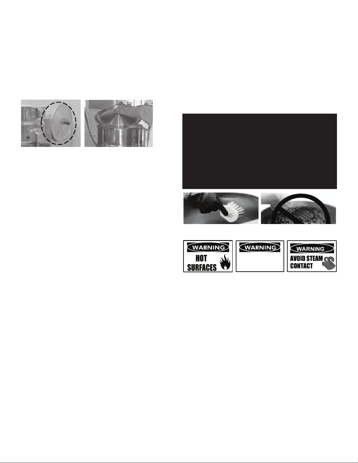
Use a brush, sponge, cloth, plastic or
rubber scraper, or plastic wool to clean.
Don’t use metal implements
or steel wool when cleaning.
OM-TD
11
Don’t scrape with tools, steel wool or other
abrasives.
Use brushes, sponges or cloth to clean your
kettles
e) Allow hot water to fully drain from
product before moving the basket away
from the kettle. Do not rest the kettle
basket on the kettle rim or pouring lip. If
the basket is too heavy for one
individual to lift and safely move, get
help from another person. Remove
product immediately from the basket into
another container, being sure to avoid
contact with hot product and hot basket
or. . .
f) Place basket with food on stable, at
surface, setting it inside a solid steamer
or bake pan, to catch any remaining hot
water which might drain from product.
Cleaning
1. Suggested Tools:
a. A good cleaner.
b. Kettle brushes in good condition.
c. A good sanitizer.
d. Film remover.
CAUTION
MOST CLEANERS ARE HARMFUL TO THE
SKIN, EYES, MUCOUS MEMBRANES, AND
CLOTHING. PRECAUTIONS SHOULD BE
TAKEN. WEAR RUBBER GLOVES,
GOGGLES OR FACE SHIELD, AND
PROTECTIVE CLOTHING. READ THE
WARNI N GS AND FOLLOW T H E
DIRECTIONS ON THE LABEL OF THE
CLEANER CAREFULLY.
2. Procedure
a. Clean food-contact surfaces as soon as
possible after use. If the unit is in
continuous use, thoroughly clean and
sanitize the interior and exterior at least
once every 12 hours.
WARNING
AVOID ANY DIRECT CONTACT WITH HOT
SURFACES. DIRECT SKIN CONTACT
COULD RESULT IN SEVERE BURNS.
b. Scrape and ush out food residues. Be
careful not to scratch the kettle with
metal implements.
c. Prepare a hot solution of the detergent/
cleaning compound as instructed by the
supplier.
d. Clean the unit thoroughly, inside and
outside.
e. Rinse the kettle thoroughly with hot
water, then drain completely.
11
OM-TD
11
WEAR EYE
PROTECTION
WEAR EYE
PROTECTION
OM-TD
11
Don’t scrape with tools, steel wool or other
abrasives.
Use brushes, sponges or cloth to clean your
kettles
e) Allow hot water to fully drain from
product before moving the basket away
from the kettle. Do not rest the kettle
basket on the kettle rim or pouring lip. If
the basket is too heavy for one
individual to lift and safely move, get
help from another person. Remove
product immediately from the basket into
another container, being sure to avoid
contact with hot product and hot basket
or. . .
f) Place basket with food on stable, at
surface, setting it inside a solid steamer
or bake pan, to catch any remaining hot
water which might drain from product.
Cleaning
1. Suggested Tools:
a. A good cleaner.
b. Kettle brushes in good condition.
c. A good sanitizer.
d. Film remover.
CAUTION
MOST CLEANERS ARE HARMFUL TO THE
SKIN, EYES, MUCOUS MEMBRANES, AND
CLOTHING. PRECAUTIONS SHOULD BE
TAKEN. WEAR RUBBER GLOVES,
GOGGLES OR FACE SHIELD, AND
PROTECTIVE CLOTHING. READ THE
WARNI N GS AND FOLLOW T H E
DIRECTIONS ON THE LABEL OF THE
CLEANER CAREFULLY.
2. Procedure
a. Clean food-contact surfaces as soon as
possible after use. If the unit is in
continuous use, thoroughly clean and
sanitize the interior and exterior at least
once every 12 hours.
WARNING
AVOID ANY DIRECT CONTACT WITH HOT
SURFACES. DIRECT SKIN CONTACT
COULD RESULT IN SEVERE BURNS.
b. Scrape and ush out food residues. Be
careful not to scratch the kettle with
metal implements.
c. Prepare a hot solution of the detergent/
cleaning compound as instructed by the
supplier.
d. Clean the unit thoroughly, inside and
outside.
e. Rinse the kettle thoroughly with hot
water, then drain completely.
11
OM-TD
11
WEAR EYE
PROTECTION
WEAR EYE
PROTECTION
SUGGESTED CLEANING SUPPLIES
1. Cleaner, such as Klenzade HC-10 or HC-32 from ECOLAB, Inc. or equivalent.
2. Kettle brushes in good condition
3. Sanitizer such as Klenzade XY-12.
4. Film remover such as Klenzade LC-30.
PRECAUTIONS
Before cleaning, shut off the kettle by turning the main power switch to “OFF,” and
shut off all electric power to the unit at a remote switch, such as the circuit breaker.
PROCEDURE
1. Clean food-contact surfaces as soon as possible after use. If the unit is in
continuous use, thoroughly clean and sanitize the interior and exterior at least
once every 12 hours.
2. Scrape and flush out food residues. Be careful not to scratch the kettle with
metal implements.
3. Prepare a hot solution of the detergent/cleaning compound as instructed
by the supplier. Clean the unit thoroughly. A cloth moistened with cleaning
solution can be used to clean controls, housings, and electrical conduits.
4. Rinse the kettle and draw-off valve parts thoroughly with hot water, then drain
completely.
5. As part of the daily cleaning program, clean soiled external and internal
surfaces. Remember to check the sides of the unit and control housing,
underside of cover, etc.

8 OM-TDB (C,A,C2T™) & TDBC (C,A,C2T™) Domestic
6. To remove burnt on foods, use a brush, sponge, cloth, plastic or rubber scraper,
or plastic wool with the cleaning solution.To reduce effort required in washing,
let the detergent solution sit in the kettle and soak into the residue. Do NOT use
abrasive materials or metal tools that might scratch the surface. Scratches
make the surface harder to clean and provide places for bacteria to grow.
Do NOT use steel wool, which may leave particles in the surface and cause
eventual corrosion and pitting.
7. The outside of the unit may be cleaned with a warm water (100°F or less)
spray. Do not use a high pressure spray.
8. The outside of the unit may be polished with a stainless steel cleaner such as
“Zepper” from Zep Manufacturing Co.
9. When equipment needs to be sanitized, use a solution equivalent to one that
supplies 200 parts per million available chlorine. Obtain advice on sanitizing
agents from your supplier of sanitizing products.
10. It is recommended that each piece of equipment be sanitized just before use.
11. Clean the kettle thoroughly. If there is difficulty removing mineral deposits or a
film left by hard water or food residues, then use a de-liming agent, following
manufacturer directions.
12. Rinse and drain the unit thoroughly before further use.
13. If cleaning problems persist, contact your cleaning product representative for
assistance. The supplier has a trained technical staff with laboratory facilities
to serve you.
CLEANING CORE PROBE
Remove all food soil from core probe by wiping entire core probe and cable
assembly with warm detergent solution and a clean cloth. Remove detergent
solution by wiping core probe and cable assembly with clean rinse water and a
cloth. Allow core probe and cable assembly to air dry. Do not immerse core probe.
Hand wash only and immediately let air dry.
MAINTENANCE
WARNING: AVOID ANY EXPOSURE TO THE STEAM BLOWING OUT OF THE PRESSURE
RELIEF VALVE. SEVERE BURNS CAN RESULT ON EXPOSED SKIN. FAILURE
TO CHECK PRESSURE RELIEF VALVE OPERATION PERIODICALLY COULD
RESULT IN PERSONAL INJURY AND/OR DAMAGE TO EQUIPMENT.
CAUTION: KEEP GREASE AWAY FROM ELECTRICAL PARTS LOCATED NEAR THE
GEARS.
WARNING: TO AVOID INJURY, READ AND FOLLOW ALL PRECAUTIONS STATED ON THE
LABEL OF THE WATER TREATMENT COMPOUND.
WARNING: USE OF ANY REPLACEMENT PARTS OTHER THAN THOSE SUPPLIED BY
THE MANUFACTURER OR THEIR AUTHORIZED DISTRIBUTORS CAN CAUSE
INJURY TO THE OPERATOR AND DAMAGE TO THE EQUIPMENT AND WILL
VOID ALL WARRANTIES.
CAUTION: INSURE ELECTRICAL POWER IS REMOVED AND THE GAS IS TURNED OFF AT
THE SHUTOFF VALVE PRIOR TO PERFORMING ANY MAINTENANCE ON THIS
KETTLE.
WARNING: THIS KETTLE IS DESIGNED TO BE WATER RESISTANT. FAILURE TO FOLLOW
PROPER MAINTENANCE PROCEDURES MAY VOID THE WARRANTY.
The pressure gauge should show a vacuum of 20 to
30 inches when the kettle is cold
The open end of the pressure relief valve
elbow must face downward.
The pressure relief valve and fill plug are located directly
behind the pressure/vacuum gauge.
PERIODIC MAINTENANCE
NOTICE: Contact an authorized representative when repairs are required.
A Maintenance & Service Log is provided at the back of this manual. Each time
maintenance is performed on your kettle, enter the date on which the work was
done, what was done, and who did it. Keep this manual on file and available
for operators to use. Periodic inspection will minimize equipment down time and
increase the efficiency of operation. The following points should be checked:
JACKET VACUUM/REMOVING AIR FROM JACKET
Every day, while the kettle is cold, read the pressure/ vacuum gauge. A positive
reading or a negative reading between zero and 20” vacuum on the pressure/
vacuum gauge indicates excess air in the jacket. Air in the jacket slows kettle
heating and can prevent the kettle from reaching operating temperature. To
remove air:
To remove air:
1. Start the unit. (See “Operation” section).
2. Make sure the elbow on the outlet of the pressure relief valve is turned so
that escaping steam is directed down toward the floor. Be sure and follow the
instructions on the attached pressure relief valve tag.
3. When the pressure/vacuum gauge reaches a positive pressure reading of 5
PSI, release trapped air by lifting the pressure relief valve ring for about one
second. Repeat this step, then let the valve ring snap closed, so the valve will
seat properly and not leak.
PRESSURE RELIEF VALVE
At least twice a month, test the pressure relief valve. Test the valve with the kettle
operating at 15 PSI (105 kPa), by holding the test ring for at least five seconds.Then
release the ring and permit the valve to snap shut. If the ring does not activate, if
there is no discharge, or if the valve leaks, stop using the kettle immediately and
contact a authorized service representative.
GREASE / LUBRICATION
1. Hand Tilt Models
At least twice a year, grease the two trunnion bearings. The bearings are
located within the kettle support housing. Remove the access panels from
the support housing with a screwdriver to gain access to the grease fittings.
Use a lithium-based, multi-purpose grease. When the access panels are
removed, the mounting bolts for the trunnion bearings and tilt switch can also
be checked for tightness. When finished, reassemble access panels to support
housing.
2. Crank Tilt Models
The gear housing has been fitted for proper lubrication of moving parts.
Since the gears do not run in oil, periodic lubrication with grease is essential.
Frequency of lubrication depends on operating conditions, but should occur
at least once every six months. The use of a Number Two grade LGI lithium
grease is recommended. Add grease through the Zerk fittings on the gear
housing until grease flows out of the bearings around the trunnion shaft. Place
a liberal amount of grease on the gear to cover the arc that is in contact with
the worm gear.

9 OM-TDB (C,A,C2T™) & TDBC (C,A,C2T™) Domestic
JACKET FILLING
Every day, before you turn on the unit, make sure the water level is approximately
in the center of the water gauge glass. The jacket was filled at the factory with the
proper amount of treated water, and is airtight, but over time steam may be vented
and water lost.
From time to time, you may need to restore the water to its proper level. The
procedure for adding water follows.
1. If you are replacing water lost as steam, use distilled water. Do not use tap
water. If you are replacing treated water that was drained from the jacket,
prepare more treated water as directed below.
2. Allow the kettle to cool completely. Remove the pipe plug from the jacket fill
assembly. Pour in the distilled or treated water. Using a funnel will help you
in this process. Hold the pressure relief valve open while you pour, to let air
escape from the jacket. Continue adding water until the water level rises to the
center of the round sight glass.
3. Air that gets into the jacket during the filling operation must be removed,
because it will make heating less efficient. Follow the procedure in Jacket
Vacuum/Removing Air From Jacket above, to restore a negative pressure
reading.
WATER TREATMENT
1. Fill a mixing container with the amount of water required. Use only distilled
water.
Model Kettle Capacity Jacket Capacity
TDB/TDBC-20 20 qt (5 gal), 18.9 liter 7 quart, 6.6 liter
TDB/TDBC-24 24 qt (6 gal), 22.7 liter 7 quart, 6.6 liter
TDB/TDBC-40 40 qt (10 gal), 37.8 liter 9 quart, 8.5 liter
TDB/TDBC-48 48 qt (12 gal), 45.4 liter 9 quart, 8.5 liter
2. Hang a strip of pH test paper on the rim of the container, with about 1 inch of
the strip below the surface of the water.
3. Stir the water continuously, while you slowly add water treatment compound
until a color between indicating a pH of 10.5 and 11.5 is reached. (Shown on
the pH test kit chart.) Judge the pH by frequently comparing the test strip with
the color chart provided in the pH test kit. If there is a problem distinguishing
color, use a pH meter.
4. Use a measuring cup to add the compound so that you may record the exact
amount used.
5. The amount may be used again, if the same water sources and compound are
used in the future. However, it is best to check the pH each time treated water
is prepared.
SEQUENCE OF OPERATION
The following “action-reaction” outline is provided to help understand how the
kettle works.
When the operator starts up the kettle by turning the power switch to “ON” and
temperature dial from “OFF” to a desired setting, the control relay closes. This
lights up the heating indicator light and causes the contactors to close, allowing
power to flow to the heating elements.When the temperature of the steam jacket
reaches the value corresponding to the dial setting, the control relay opens. This
turns off the heating indicator light and causes the contactors to open, stopping
the power to the heaters. As soon as the control senses that the kettle is cooling
below the set point, the switch closes, the heating indicator light comes on,
the contactors close, and the heaters come on again. On-off cycling continues,
keeping the kettle at the set temperature. This is why the heating indicator light
cycles on and off during normal operation. Every time the kettle is tilted, the tilt
cut-off switch interrupts the power supply to the heaters, so that the heating
elements will not operate while not submerged in the jacket water.
If steam pressure greater than 50 PSI is generated in the jacket, the pressure
relief valve will open and relieve the excess pressure.
In the event that the jacket water level gets too low and the heating elements
overheat, the high limit control will open and shut off power to the elements until
the kettle cools. Setting the operating power switch to “OFF” shuts down all
control and heating circuits.
REPLACEMENT PARTS
To order parts, contact your Authorized Service Agent. Supply the model
designation, serial number, part description, part number, quantity, and when
applicable, voltage and phase.
CONTACT US
If you have questions pertaining to the content in this manual, contact Unified
Brands at 888-994-7636.

10 OM-TDB (C,A,C2T™) & TDBC (C,A,C2T™) Domestic
TROUBLESHOOTING
This unit is designed to operate smoothly and efficiently if properly maintained.
However, the following is a list of checks to make in the event of a problem.
Wiring diagrams are found at the end of this manual. When in doubt, turn unit
off and call for service at 888-994-7636. If an item on the check list is marked
with (X), it means that the work should be done by an Authorized Service Agent.
SYMPTOM WHO WHAT TO CHECK
Display not lit
(
Advanced & C2T only)
User a. That power supply is on.
Authorized
Service Rep
Only
b. Fuses, accessible by removing caps on the side of
the control box.
c. For loose or broken wires. X
d. Temperature controller functioning, by listening
for a click when the switch opens or closes and
verifying LEDs on back of board. X
e. Contactor functioning. X
PROB in display
(
Advanced & C2T only)
Authorized
Service Rep
Only
a. For loose or broken wires or damaged/failed RTD
probe. X
b. PCB board malfunction/failure
HI in display
(
Advanced & C2T only)
Authorized
Service Rep
Only
a. For loose or broken wires or damaged/failed RTD
probe. X
b. PCB board malfunction/failure
Kettle is hard to tilt Authorized
Service Rep
Only
a. Gears for foreign materials, and lubrication. X
b. Gears for alignment. X
c. Worn gears or broken gears. X
Kettle will not heat,
and heating indicator
will not come on
User a. Electric power supply to the unit. (Check the circuit
breaker.)
b. Water level in jacket.
Authorized
Service Rep
Only
c. Control circuit fuses. Replace a blown fuse only
with a fuse of the same AMP rating. X
d. For loose or broken wires. X
e. Tilt cut-off switch. X
f. That pressure switch is open. X
g. Operation of temperature control. X
h. Low water cutoff. X
Kettle will not heat,
but heating indicator
comes on
Authorized
Service Rep
Only
a. Temperature control calibration and offsets. X
b. Heater elements with ohmmeter for ground short or
open element. If element is defective, call service. X
Kettle continues
heating after it
reaches the desired
temperature
User a. Control knob setting.
Authorized
Service Rep
Only
b. Temp control circuit for short. X
c. Temp control operation. The contacts should click
when the dial is rotated above and below the
setting for the temperature of the kettle. X
d. Contactor, to determine whether it is energized or
stuck. X
Kettle stops heating
before it reaches the
desired temperature
User a. Control knob setting.
Authorized
Service Rep
Only
b. Temp control calibration and offsets. X
c. Temp control operation. The contacts should click
when the dial is rotated above and below the
setting for the temperature of the kettle. X
Kettle heats slowly User a. For air in the jacket. See “Jacket Vacuum” in the
“Maintenance” section of this manual.
Authorized
Service Rep
Only
b. Heater elements with ohmmeter for ground short
or open element. If an element is defective, call
service. X
c. Voltage of main power source. X
Pressure Relief Valve
pops
User a. For air in the jacket. See “Jacket Vacuum” in the
“Maintenance” section of this manual.
Authorized
Service Rep
Only
b. Pressure switch setting. X
c. Temp control operation. The contacts should click
when the dial is rotated above and below the
setting for the temperature of the kettle. X
d. Pressure relief valve. If the valve pops at pressures
below 49 PSI, replace it.
e. ontactor, to determine whether it is energized. X
CPER in display (C2T
only)
User a.
That core probe is plugged into the receptacle.
Authorized
Service Rep
Only
b. For loose or broken wires or damaged/failed RTD probe.
X
c. PCB board malfunction/failure. X

11 OM-TDB (C,A,C2T™) & TDBC (C,A,C2T™) Domestic
Parts List
TDB Models

12 OM-TDB (C,A,C2T™) & TDBC (C,A,C2T™) Domestic
Parts List
TDB Models

13 OM-TDB (C,A,C2T™) & TDBC (C,A,C2T™) Domestic
Parts List
TDBC Models

14 OM-TDB (C,A,C2T™) & TDBC (C,A,C2T™) Domestic
Parts List
To order parts, contact your Authorized Service Agent. Supply the model designation, serial number, part description, part number, quantity, and when applicable,
voltage and phase.
Key Description Part No.
1WATER FILL ASSEMBLY 137433
2SAFETY VALVE 097005
3CHECK VALVE 096915
4PRESSURE GAUGE 084208
5KNOB 175095
6HAND & BALL KNOB ASSEMBLY 012694
7KETTLE BODY ASSEMBLY, 20 QT 175062
7a KETTLE BODY ASSEMBLY, 20 QT, 480V 175061
7b KETTLE BODY ASSEMBLY, 24 QT 175067
7c KETTLE BODY ASSEMBLY, 24 QT, 480V 175068
7d KETTLE BODY ASSEMBLY, 40 QT 175072
7e KETTLE BODY ASSEMBLY, 40 QT, 480V 175071
7f KETTLE BODY ASSEMBLY, 48 QT 175084
7g KETTLE BODY ASSEMBLY, 48 QT, 480V 175085
8BASE & PEDESTAL ASSEMBLY - 20/24QT HAND TILT 174752
8a BASE & PEDESTAL ASSEMBLY - 40/48QT HAND TILT 175362
8b BASE & PEDESTAL ASSEMBLY - 20/24QT CRANK TILT 175358
8c BASE & PEDESTAL ASSEMBLY - 40/48QT CRANK TILT 175296
9a LIGHT, AMBER 116384
9b LIGHT, RED 116383
10 POWER SWITCH 176921
11A 2" ALUMINUM KNOB, CLASSIC CONTROL 175095
11B 2" ALUMINUM KNOB, ADVANCED & C2T 174829
12 NUT, ROTARY SHAFT SEAL(NOT SHOWN) 101145
13 SIGHT GLASS 108554
14 LIGHT MOUNT BRACKET(NOT SHOWN) 175222
15 LIGHT MOUNT SPACER(NOT SHOWN) 175221
16 HAND TILT MECHANISM ASSEMBLY 137741
17 PEDESTAL WELDMENT - HAND TILT 140321
-
PEDESTAL WELDMENT - CRANK TILT
174630
18 ELECTRICAL MOUNT ASSEMBLY(CRANK TILT) - 208/240V 175229
18a ELECTRICAL MOUNT ASSEMBLY - 480V 175579
19 ELECTRICAL MOUNT ASSEMBLY(HAND TILT) - 208/240V 175439
19a ELECTRICAL MOUNT ASSEMBLY - 480V 175440
20 TILT SWITCH 002982
21 CONTACTOR 148102
22 GROUND TERMINAL 129714
23 TERMINAL BLOCK 003888
24 FUSE HOLDER 077854
25 FUSE, 3 AMP 77853
26 TRANSFORMER, 208/240V 137441
26a TRANSFORMER, 480V 137694
Key Description Part No.
27 WATER LEVEL BOARD 122192
28 CONNECTOR 140416
29 CLASSIC CONTROL 174843
30A ADVANCED CONTROL 174837
30B C2T CONTROL 176895
31 RTD PROBE(NOT SHOWN) 175429
32 PRESSURE SWITCH 096963
33 ELECTRODE WATER LEVEL 015589
34 ELEMENT - 20/24 208/240V 001706
34a ELEMENT - 20/24 480V 010996
34b ELEMENT - 40/48 208/240V 011094
34c ELEMENT - 40/48 480V 011088
xCRANK TILT MECHANISM ASSEMBLY -
35 GEAR CARRIER ASSEMBLY 124741
36 HANDWHEEL SHAFT 122374
37 WORM GEAR 128001
38 HANDWHEEL ASSEMBLY 124719
39 KEY, 1/4 SG X 1" 122371
40 BEARING BACK ASSEMBLY 128021
41 ROLL PIN .25 X 1.25 012614
42 ROLL PIN .25 X 1.625 128036
43 PLUG PIPE 010286
44 FITTING, GREASE 90 012195
45 BRASS FITTING, 1/8 NPT 175231
46 WASHER, SPLIT LOCK 3/8 005618
47 SCREW, 3/8-16 X 1 HEX HEAD 005612
48 WASHER, FLAT 3/8 005830
49 GEAR SECTOR ASSEMBLY 128028
50 BEARING ROLLER 002790
51 RETAINING RING, 1.5" 124764
52 COVER ELEMENT HOUSING 003141
53 STATION COVER 175237
54 DECAL OPERATING INSTRUCTIONS - CLASSIC CTRL 175298
55 DECAL OPERATING INSTRUCTIONS - ADVANCED CTRL 175610
xHARNESS, HIGH VOLTAGE 149945
xHARNESS, CONTROL, TDB 175289
xHARNESS, ELEMENT 148718
xFERRITE BEAD (NOT SHOWN) 175836
x OVERLAY, C2T 176892
x CORE PROBE, TDB-20 & 24, C2T 176677
x CORE PROBE, TDB-40 & 48, C2T 176678
x BRACKET, CORE PROBE, TDB-20 & 24, C2T 176658
x BRACKET, CORE PROBE, TDB-40 & 48, C2T 176659
x BRACKET ASSEMBLY, CORE PROBE STORAGE 177091
x SOCKET, PANEL MOUNT ASSY, CORE PROBE, C2T 176925
x CAP, SOCKET, PANEL MOUNT, CORE PROBE, C2T 176927
x WIRE HARNESS, CONTROL, CORE PROBE, C2T 176920
x HARNESS, CONTROL, TDB, C2T 177262
x- Item not depicted/called out in drawing or photograph

15 OM-TDB (C,A,C2T™) & TDBC (C,A,C2T™) Domestic
Wiring Diagram
Classic Control Models

16 OM-TDB (C,A,C2T™) & TDBC (C,A,C2T™) Domestic
Wiring Diagram
Advanced & Cook2Temp™
Control Models

17 OM-TDB (C,A,C2T™) & TDBC (C,A,C2T™) Domestic
Service Log
Model No: Purchased From:
Serial No: Location:
Date Purchased: Date Installed:
Purchase Order No: For Service Call:
Date Maintenance Performed Performed By
This manual suits for next models
9
Table of contents
Other Groen Kettle manuals

Groen
Groen TDB/7 Operating manual

Groen
Groen EE-20 User manual

Groen
Groen D User manual

Groen
Groen TDH 24C User manual

Groen
Groen TDBC 20C User manual

Groen
Groen DEE/4-20 Series User manual

Groen
Groen AH/1E Domestic User manual

Groen
Groen EE Domestic User manual

Groen
Groen groen TDBCE Series User manual

Groen
Groen DEES-40 User manual

Groen
Groen TDC/3-3 User manual

Groen
Groen TDB-20 TA/2 User manual

Groen
Groen TDB/6 Operating manual

Groen
Groen EE-20 User manual

Groen
Groen AH-30 User manual

Groen
Groen DEE/4-40C User manual

Groen
Groen TDH User manual

Groen
Groen AH/1 User manual

Groen
Groen TDB/7 Operating manual

Groen
Groen TDB/8-20-CFC User manual