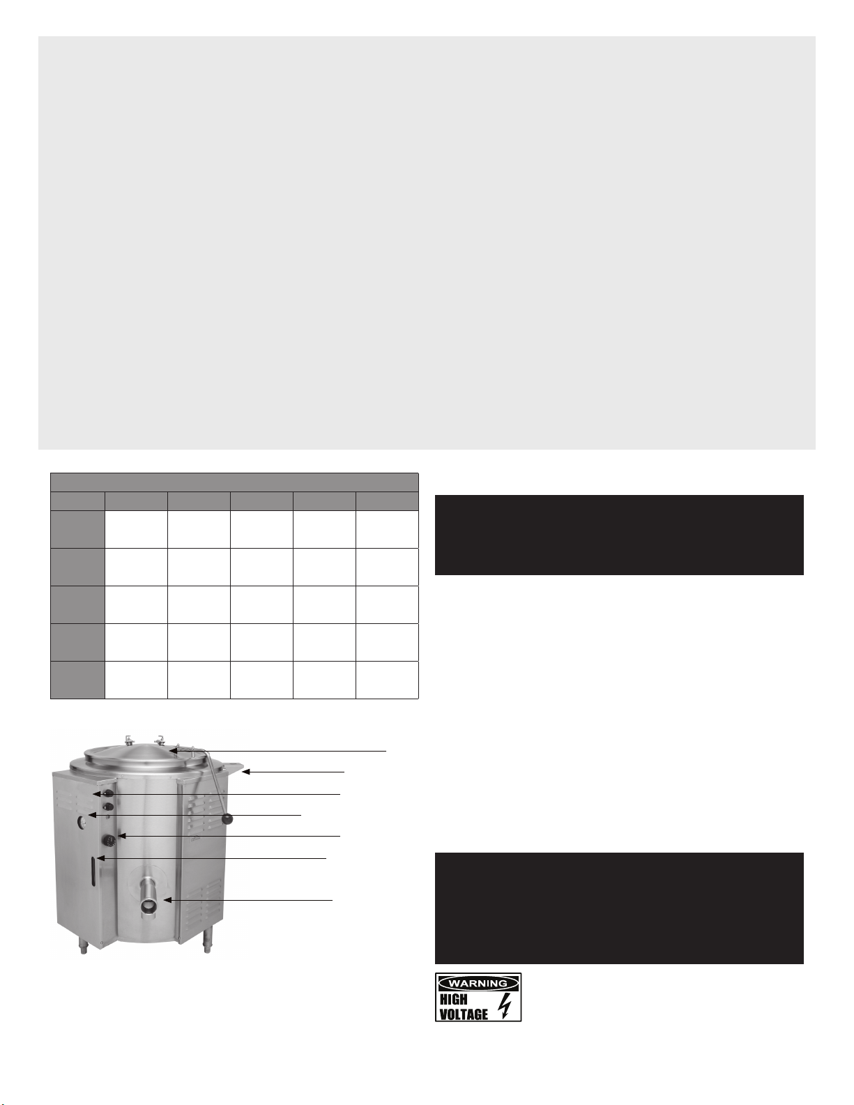
Groen EE Domestic User manual

OPERATOR MANUAL
IMPORTANT INFORMATION, KEEP FOR OPERATOR
THIS MANUAL MUST BE RETAINED FOR FUTURE REFERENCE. READ,
UNDERSTAND AND FOLLOW THE INSTRUCTIONS AND WARNINGS
CONTAINED IN THIS MANUAL.
FOR YOUR SAFETY Instructions to be followed in the event user smells
gas. This information shall be obtained by consulting your local gas
supplier. As a minimum, turn off the gas and call your gas company and
your authorized service agent. Evacuate all personnel from the area.
WARNING Improper installation, adjustment, alteration, service or
maintenance can cause property damage, injury or death. Read the
installation, operating and maintenance instructions thoroughly before
installing or servicing this equipment.
NOTIFY CARRIER OF DAMAGE AT ONCE It is the responsibility of the
consignee to inspect the container upon receipt of same and to determine
the possibility of any damage, including concealed damage. Unified
Brands suggests that if you are suspicious of damage to make a notation
on the delivery receipt. It will be the responsibility of the consignee to file
a claim with the carrier. We recommend that you do so at once.
Manufacture Service/Questions 888-994-7636.
PART NUMBER 147399, REV. G (02/21)
This manual provides information for:
STEAM JACKETED KETTLE
MODELS EE DOMESTIC
EQUIPMENT DESCRIPTION
Groen Model EE are floor-mounted, tilting, steam-jacketed kettles which have
thermostatically controlled, self-contained, electrically-heated steam supplies
and appropriate controls, mounted on a sturdy base. Heat produced by electric
heating elements boils water in a reservoir below the jacket to produce steam
under pressure.
The kettle is surrounded by air-insulated stainless steel sheathing. Stainless
steel panels enclose all of the controls. Three stainless steel, tubular legs
support the unit.
EE kettles are available in 20, 40, 60, 80 and 100 gallon capacities. Kettle bodies
are welded into one piece. Models are all equipped with a sanitary tangent
draw-off (product faucet) valve and a stainless steel strainer. This standard
draw-off is two inches in diameter, and uses a compression disc valve. The unit
is controlled with a thermostat, which turns electric power on or off, and sets
the cooking temperature.
Instruments are provided to show what is happening inside the unit:
• Water gauge glass: shows the level of water within the steam jacket
• Pressure/vacuum gauge: shows the steam pressure and if there is air in the
jacket
• Indicator lamp: Lights when the kettle is being heated
Automatic controls within the unit:
• Contactor: Controlled by the thermostat, turns heating element power on or off
• Low-water cutoff:Turns off power to keep heating elements from overheating
if water loss exposes them above the water level.
• Safety valve: Releases steam if jacket pressure gets too high
The jacket is filled at the factory with water that contains rust inhibitors. When
air is removed from the jacket, the kettle efficiently provides a uniform heating
temperature range of 150oF to approximately 270oF (65 to 132oC). This range
allows the kettle to be used for warming, simmering, boiling or braising.
The interior of the kettle is polished to a 180 emery grit finish and the exterior is
given a uniform Number 4 finish. The unit is ASME shop inspected and registered
with the National Board for working pressures up to 30 PSI.
Optional equipment for the EE and AE kettles includes:
• Three inch draw-off valve
• 1/4” perforated or solid disc strainer
• Basket inserts (TRI-BC)
REFERENCES
KLENZADE SALES CENTER ECOLAB, Inc.
370 Wabasha
St. Paul, Minnesota 55102
800/352-5326 or 612/293-2233
NFPA/70 The National Electrical Code
NATIONAL FIRE PROTECTION ASSOCIATION
60 Battery March Park
Quincy, Massachusetts 02269
ECONOMICS LABORATORY, INC.
St. Paul, Minnesota 55102
888-994-7636, fax 888-864-7636
unifiedbrands.net
NSF INTERNATIONAL
798 N. Dixboro Rd.
P.O. Box 130140
Ann Arbor, Michigan 48113-0140
UNDERWRITERS LABORATORIES, INC.
333 Pfingsten Road
Northbrook, Illinois 60062
ZEP MANUFACTURING CO.
1310-T Seaboard Industrial Blvd.
Atlanta, Georgia 30318
The information in this document is Confidential and shall not be disclosed to any third party without the express written
consent of Unified Brands. Information contained in this document is known to be current and accurate at the time of printing/
creation. Unified Brands recommends referencing our product line websites, unifiedbrands.net, for the most updated product
information and specifications. © 2022 Unified Brands. All Rights Reserved.
• Water fill faucets
• Automatic water filler
• Kettle brush kit

2 OM-EE
IMPORTANT - READ FIRST - IMPORTANT
CAUTION: BE SURE ALL OPERATORS READ, UNDERSTAND AND FOLLOW THE
OPERATING INSTRUCTIONS, CAUTIONS, AND SAFETY INSTRUCTIONS
CONTAINED IN THIS MANUAL.
WARNING: THIS UNIT IS INTENDED FOR USE IN THE COMMERCIAL HEATING, COOKING
AND HOLDING OF WATER AND FOOD PRODUCTS, PER THE INSTRUCTIONS
CONTAINED IN THIS MANUAL. ANY OTHER USE COULD RESULT IN SERIOUS
PERSONAL INJURY OR DAMAGE TO THE EQUIPMENT AND WILL VOID
WARRANTY.
WARNING: KETTLE MUST BE INSTALLED BY PERSONNEL QUALIFIED TO WORK WITH
ELECTRICITY. IMPROPER INSTALLATION CAN RESULT IN INJURY TO
PERSONNEL AND/OR DAMAGE TO EQUIPMENT.
DANGER: ELECTRICALLY GROUND THE UNIT AT THE TERMINAL PROVIDED. FAILURE
TO GROUND UNIT COULD RESULT IN ELECTROCUTION AND DEATH.
WARNING: AVOID ALL DIRECT CONTACT WITH HOT EQUIPMENT SURFACES. DIRECT
SKIN CONTACT COULD RESULT IN SEVERE BURNS.
WARNING: AVOID ALL DIRECT CONTACT WITH HOT FOOD OR WATER IN THE KETTLE.
DIRECT CONTACT COULD RESULT IN SEVERE BURNS.
CAUTION: DO NOT OVER FILL THE KETTLE WHEN COOKING, HOLDING OR CLEANING.
KEEP LIQUIDS A MINIMUM OF 2-3” (5-8 CM) BELOW THE KETTLE BODY RIM
TO ALLOW CLEARANCE FOR STIRRING, AND BOILING.
WARNING: TAKE SPECIAL CARE TO AVOID CONTACT WITH HOT KETTLE BODY OR HOT
PRODUCT WHEN ADDING INGREDIENTS, STIRRING OR TRANSFERRING
PRODUCT TO ANOTHER CONTAINER.
CAUTION: KEEP FLOORS IN FRONT OF KETTLE WORK AREA CLEAN AND DRY. IF
SPILLS OCCUR, CLEAN IMMEDIATELY, TO AVOID SLIPS OR FALLS.
INSPECTION & UNPACKING
CAUTION: SHIPPING STRAPS ARE UNDER TENSION AND CAN SNAP BACK WHEN CUT.
TAKE CARE TO AVOID PERSONAL INJURY OR DAMAGE TO THE UNIT BY
STAPLES LEFT IN THE WALLS OF THE CARTON.
CAUTION: THIS UNIT IS VERY HEAVY. INSTALLER SHOULD OBTAIN HELP AS NEEDED
TO LIFT THIS WEIGHT SAFELY
The unit will arrive in a heavy shipping carton and will be banded to a skid.
Immediately upon receipt, inspect the carton carefully for exterior damage.
Write down the model number, serial number, and installation date, and retain this
information for future reference. Space for these entries is provided at the top of
the Service Log at the back of this manual. Keep this manual on file and available
for operators to use.
Carefully cut any polyester straps around the carton and detach the sides of the
box from the skid. Pull the carton up off the unit.
Thoroughly inspect the unit for concealed damage. Report any shipping damage or
incorrect shipments to the delivery agent.
When installation is to begin, carefully cut any straps which hold the unit on the
skid. Lift the unit straight up off the skid. Examine packing materials to be sure that
loose parts are not discarded with the materials.
INSTALLATION
WARNING: INSTALLATION OF THE KETTLE MUST BE DONE BY A CERTIFIED
ELECTRICIAN OR AUTHORIZED REPRESENTATIVE QUALIFIED TO WORK
WITH ELECTRICITY. IMPROPER INSTALLATION CAN RESULT IN INJURY TO
PERSONNEL AN/OR DAMAGE TO EQUIPMENT.
CAUTION: ELECTRICALLY GROUND THE UNIT AT THE TERMINAL PROVIDED. FAILURE
TO GROUND THE UNIT COULD RESULT IN ELECTROCUTION AND DEATH. DO
NOT FORCE THE PLUG OR ALTER IT TO OVERRIDE GROUNDING FEATURES.
WARNING: FAILURE TO CHECK SAFETY VALVE OPERATION PERIODICALLY COULD RESULT
IN PERSONAL INJURY AND/OR DAMAGE TO EQUIPMENT.
WARNING: WHEN TESTING, AVOID ANY EXPOSURE TO THE STEAM BLOWING OUT OF THE
SAFETY VALVE. DIRECT CONTACT COULD RESULT IN SEVERE BURNS.
WARNING: TO AVOID INJURY, READ AND FOLLOW ALL PRECAUTIONS STATED ON THE
LABEL OF THE WATER TREATMENT COMPOUND.
WARNING: BEFORE REPLACING ANY PARTS, DISCONNECT THE UNIT FROM THE ELECTRIC
POWER SUPPLY.
WARNING: KEEP WATER AND SOLUTIONS OUT OF CONTROLS AND ELECTRICAL
EQUIPMENT. NEVER USE A HIGH PRESSURE HOSE TO CLEAN KETTLE
SURFACES.
CAUTION: MOST CLEANERS ARE HARMFUL TO THE SKIN, EYES, MUCOUS MEMBRANES
AND CLOTHING. PRECAUTIONS SHOULD BE TAKEN. WEAR RUBBER GLOVES,
GOGGLES OR FACE SHIELD AND PROTECTIVE CLOTHING. CAREFULLY READ
THE WARNINGS AND FOLLOW THE DIRECTIONS ON THE LABEL OF THE
CLEANER TO BE USED.
CAUTION: USE OF ANY REPLACEMENT PARTS OTHER THAN THOSE SUPPLIED BY GROEN
OR THEIR AUTHORIZED DISTRIBUTORS CAN CAUSE OPERATOR INJURY AND
DAMAGE TO THE EQUIPMENT, AND WILL VOID ALL WARRANTIES.
IMPORTANT:
SERVICE PERFORMED BY OTHER THAN FACTORY AUTHORIZED PERSONNEL
WILL VOID WARRANTIES.
WARNING: DO NOT HEAT AN EMPTY KETTLE. EXCESSIVE STEAM PRESSURE COULD
DEVELOP.
KETTLE CHARACTERISTICS
EE-20 EE-40 EE-60 EE-80 EE-100
Capacity 20gal (75L) 40gal
(150L)
60gal
(226L)
80gal
(300L)
100gal
(378L)
Diameter 26in
(660mm)
32in
(813mm)
36in
(914mm)
38in
(965mm)
38in
(965mm)
Rim Height 37in
(940mm)
37in
(940mm)
40in
(1016mm)
44in
(1118mm)
44in
(1118mm)
Total Width 26in
(660mm)
32 in
(813mm)
36in
(914mm)
38in
(965mm)
38in
(965mm)
Front to
Back
39-3/4in
(1010mm)
49-3/4in
(1264mm)
48-3/4in
(1238mm)
50-3/4in
(1289mm)
50-3/4in
(1289mm)
Cover
Faucet Bracket
Control Housing
Pressure/Vacuum Gauge
Thermostat Dial
Water Gauge Glass
Tangent Draw-Off

3 OM-EE
The Groen cooker/mixer is provided with complete internal wiring. It is ready for
immediate connection. The completed unit was operated at the factory to check
the controls, mixer and jacket heater.
Any mechanical or electrical changes must be approved in by Groen’s Food Service
Engineering Department.
1. Set the kettle in place and level it by turning the bullet feet to adjust leg length.
Allow clearance around the unit for cleaning, maintenance and service.
2. Confirm that the jacket water level is above the mid point of the gauge glass.
If the level is low, follow the instructions under “Jacket Filling and Water
Treatment”.
3. The open end of the elbow on the outlet of the safety valve must face
downward. If it does not, turn it to the correct position.
4. Provide electrical power specified on the equipment electrical information
plate. Observe local codes and/or The National Electrical Code in accordance
with ANSI/NFPA 70 - (current edition).
5. The equipment is shipped ready for three phase operation. Refer to the wiring
diagram for single phase operation.
6. Bring in the electrical supply through opening on control housing that is
located below the thermostat dial. An opening is provided for 1-1/4” (35 mm)
conduit fitting.
Water tight, 90° elbow connection is recommended. Incoming power
connections are made at the terminal block.
Observe local codes and/or the National Electrical Code in compliance with
ANSI/NFPA 70 (latest edition). When there is a choice between applicable
codes, Groen recommends following the more stringent code. (A BX connection
is not recommended.)
7. Electrically ground the unit at the terminal provided.
8. Check the following to confirm that your kettle is properly installed:
• Room for cleaning and servicing
• The kettle is level
• The correct amount of water is in the kettle jacket
• Safety valve is pointed down
• Unit is connected with a waterproof electric power supply of the proper
voltage, phase and amperage rating
ELECTRICAL SPECIFICATIONS
EE-20 EE-40 EE-60 EE-80 EE-100
KW AMP KW AMP KW AMP KW AMP KW AMP
208 Volt
Single-
Phase
11 52 22 104* - - - - - -
208 Volt
3-Phase 11 30 22 60 32 90 32 90 32 90
240 Volt
Single-
Phase
12 50 24 101* - - - - - -
240 Volt
3-Phase 12 29 24 58 36 87 36 87 36 87
480 Volt
Single-
Phase
12 25 24 50 - - - - - -
480 Volt
3-Phase 12 15 24 29 36 44 36 44 36 44
* Use Kit P/N 170960 for larger terminal block, when operating EE-40 on 208 or 240V single phase.
INITIAL START-UP
IMPORTANT:
BE SURE ALL OPERATORS READ, UNDERSTAND AND FOLLOW THE
OPERATING INSTRUCTIONS, CAUTIONS AND SAFETY INSTRUCTIONS
CONTAINED IN THIS MANUAL.
WARNING: AVOID ALL DIRECT CONTACT WITH HOT SURFACES. DIRECT SKIN CONTACT
COULD RESULT IN SEVERE BURNS.
AVOID ALL DIRECT CONTACT WITH HOT FOOD OR WATER IN THE KETTLE.
DIRECT CONTACT COULD RESULT IN SEVERE BURNS.
Now that the kettle has been installed, you should test it to ensure that the unit is
operating correctly.
1. Remove all literature and packing materials from inside and outside of the unit.
2. Clean out any material which might clog or damage the draw-off (product
outlet).
3. Install the draw-off valve (packed separately) by sliding the assembly into the
tangent and hand-tightening the large stainless steel nut.
3. Turn on the electrical service to the unit.
4. Pour water into the kettle until it is about six inches deep (150 mm).
5. Test draw-off valve operation by opening it all the way, then closing it before
all the water runs out.
6. Following “To Start Kettle” instructions in the “Operation” section of this
manual, begin heating the water at the highest thermostat setting. The heating
indicator light should come on immediately, and heating should continue until
the water boils. Each day, confirm the jacket water level by checking the water
gauge.
7. To shut down the unit, turn the thermostat dial to “OFF”.
If the unit functions as described above, it is ready for use. If the unit does not
function as described, contact your local Groen Certified Service Agency.
OPERATION
WARNING: OPEN THE KETTLE LID CAREFULLY TO AVOID STEAM WHICH MAY ESCAPE.
DIRECT CONTACT COULD RESULT IN SEVERE BURNS.
CAUTION: KEEP FLOORS IN FRONT OF THE KETTLE WORK AREA CLEAN AND DRY. IF
SPILLS OCCUR, CLEAN AT ONCE TO AVOID SLIPS OR FALLS.
CAUTION: DO NOT OVERFILL THE KETTLE WHEN COOKING, HOLDING OR CLEANING.
KEEP LIQUIDS AT LEAST 2-3” (5-8 CM) BELOW THE KETTLE RIM TO ALLOW
CLEARANCE FOR STIRRING, BOILING AND SAFE PRODUCT TRANSFER.
WARNING: AVOID ALL DIRECT CONTACT WITH HOT FOOD OR WATER IN THE KETTLE.
DIRECT CONTACT COULD RESULT IN SEVERE BURNS.
The operator controls kettle heating with the thermostat dial. The dial turns heating
element power on or off and sets the kettle operating temperature.

4 OM-EE
TO START KETTLE
1. EVERY DAY make sure the jacket water level is between the marks on the
gauge glass. If the level is too low, see “Jacket Filling and Water Treatment”.
2. While the kettle is cold, check the pressure gauge. If the gauge does not show
20 to 30 inches of vacuum (that is, a reading of 20 to 30 below 0), see “Jacket
Vacuum”. Be sure that the pressure/vacuum gauge shows at least 20 inches
of vacuum.
3. Make sure that the strainer covers the draw-off valve outlet at the bottom of
the kettle. This keeps food solids from collecting in the draw-off area.
4. Turn the thermostat dial to the desired setting. The indicator light will confirm
that the kettle is heating. Cycling of the light on and off shows that the kettle is
being held at the set temperature. Once in each cycle contactors in the support
housing will make a clicking sound. This is normal.
TO TRANSFER PRODUCT OR EMPTY KETTLE
1. The kettle is emptied by means of its draw-off valve, by ladling product out, or
with the optional tri-basket insert.
2. Use of Optional Basket Insert: The optional kettle basket insert set will assist in
cooking water-boiled products such as eggs, potatoes, vegetables, shell fish,
pasta and rice. The nylon mesh liner must be used for products smaller than
the basket mesh size, (approximately 1/4” (6 mm). This includes rice and small
pasta shapes.
Tips For Use:
a) Allow for displacement of the three baskets and product. This may mean
only filling the kettle half way. Test baskets and product displacement with
the kettle OFF, and with cold water in the kettle.
b) Load baskets on a level, stable work surface.
c) Lift loaded baskets with both hands. Get help from another person if the
basket is too heavy for safe handling.
d) Slowly lower product into kettle and securely hook the basket to the “Y”
frame.
e) When removing baskets with cooked product, lift straight up, ensuring
basket bottoms clear the kettle rim. Wear protective oven mitts and
protective apron.
f) Allow hot water to fully drain from product, before moving basket away
from the kettle. Do not rest baskets on kettle rim or pouring lip. If baskets
are too heavy for one individual to lift and safely move, get help. Remove
product immediately from basket into another container, being sure to
avoid contact with hot product and hot basket or. . .
g) Place baskets with food on a stable, flat surface, inside a solid steamer or
bake pan, to catch any remaining hot water draining from product.
TO TURN OFF THE KETTLE
1. Turn the thermostat dial to “OFF.”
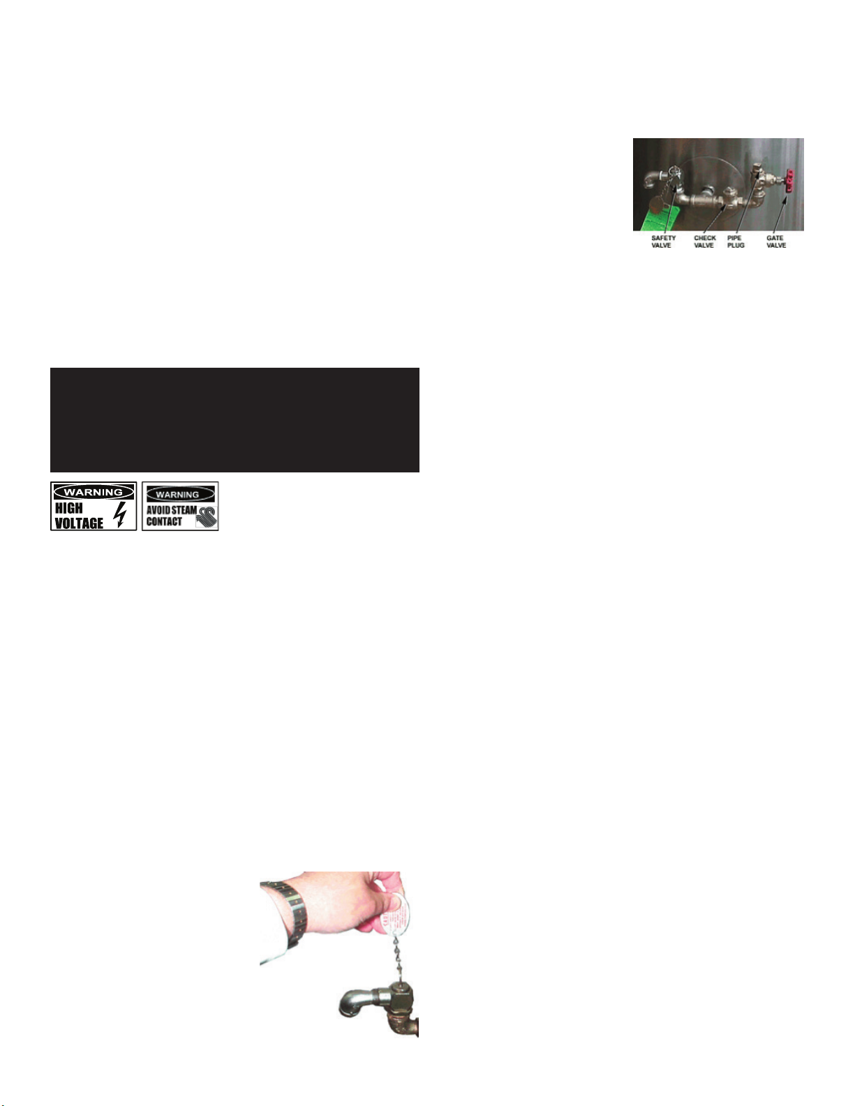
2. Before the unit is serviced, or if it will be off for a week or more:
a. Set the thermostat to “OFF.”
b. Turn off electric power to the unit at the circuit breaker or fuse.
CLEANING
WARNING: KEEP WATER AND SOLUTIONS OUT OF CONTROLS AND ELECTRICAL
EQUIPMENT. DO NOT USE A HIGH PRESSURE HOSE TO CLEAN THE CONTROL
CONSOLE, ELECTRICAL CONNECTIONS, ETC.
WARNING: AVOID ANY DIRECT CONTACT WITH HOT SURFACES. DIRECT SKIN CONTACT
COULD RESULT IN BURNS.
CAUTION: MOST CLEANERS ARE HARMFUL TO THE SKIN, EYES, MUCOUS
MEMBRANES AND CLOTHING. PRECAUTIONS SHOULD BE TAKEN TO WEAR
RUBBER GLOVES, GOGGLES OR FACE SHIELD AND PROTECTIVE CLOTHING.
CAREFULLY READ THE WARNINGS AND FOLLOW LABEL DIRECTIONS.
NOTICE: NEVER LEAVE A CHLORINE SANITIZER IN CONTACT WITH STAINLESS STEEL
SURFACES LONGER THAN 30 MINUTES. LONGER CONTACT CAN CAUSE
STAINING AND CORROSION.
CAUTION: DO NOT MIX THE PARTS OF DIFFERENT DRAW-OFF ASSEMBLIES DURING
WASHING. THE PARTS ARE NOT ALWAYS INTERCHANGEABLE.
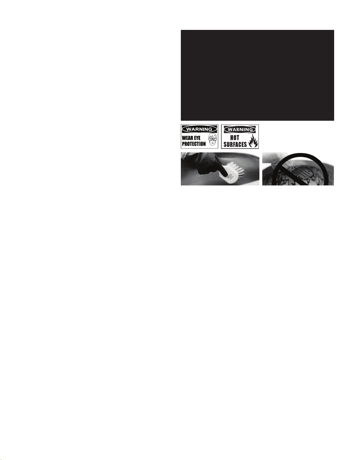
Use a brush, sponge, cloth, plastic or rubber scraper, or plastic wool to clean. Don’t use metal
implements or steel wool when cleaning.
SUGGESTED CLEANING SUPPLIES
1. Cleaner, such as Klenzade HC-10 or HC-32 from ECOLAB, Inc.
2. Kettle brushes in good condition (and a bottle brush, for the draw-off).
3. Sanitizer such as Klenzade XY-12.
4. Film remover such as Klenzade LC-30.
PRECAUTIONS
Before cleaning, shut off the kettle by turning the thermostat dial to “OFF” and
unplug the unit or shut off its electric power at a remote switch, such as the circuit
breaker.
PROCEDURE
1. Clean food contact surfaces as soon as possible after use, preferably while the
kettle is still warm. If the unit is in continuous use, clean and sanitize inside
and outside at least once every 12 hours.
2. Scrape and flush out food residues. Be careful not to scratch the kettle with
metal implements. Close the draw-off.
3. Prepare a solution of the detergent/cleaning compound as instructed by the
supplier. Clean the unit thoroughly. A cloth moistened with cleaning solution
can be used to clean controls and electrical conduits.
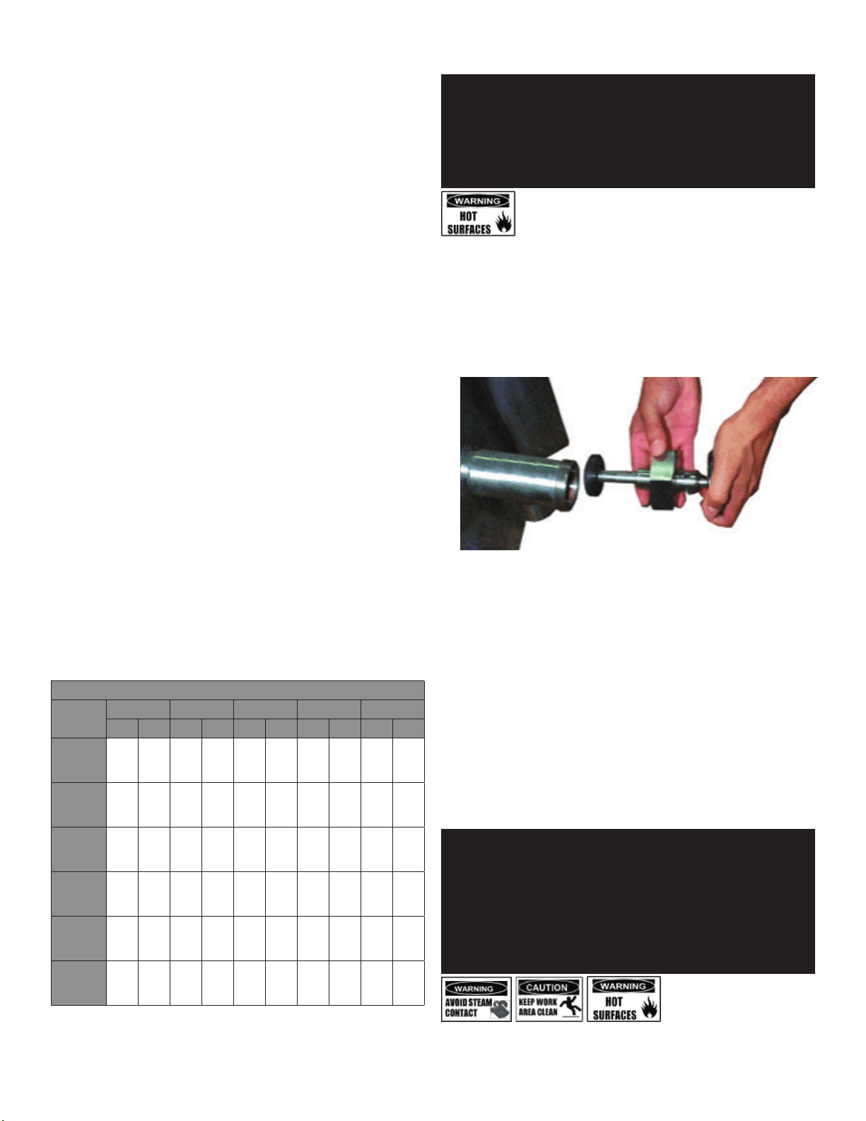
4. Disassemble the tangent draw-off valve. Clean the draw-off port and each
valve part with a brush.
5. Rinse the kettle and draw-off valve parts thoroughly with hot water to remove
every trace of detergent. Drain completely and allow them to AIR dry or wipe
them dry. (The agitator may be cleaned in a dishwasher).
6. As part of the daily cleaning program, clean soiled external and internal
surfaces. Remember to check the sides and back of the unit.
7. To remove stuck materials, use a brush, sponge, cloth, plastic or rubber
scraper, or plastic wool with the cleaning solution. To reduce effort required in
washing, let the detergent solution sit in the kettle and soak into the residue.
Do NOT use abrasive materials or metal tools that might scratch the surface.
Scratches make the surface harder to clean and provide places for bacteria
to grow. Do NOT use steel wool, which may leave particles in the surface and
cause eventual corrosion and pitting.

5 OM-EE
8. The outside of the unit may be polished with a stainless steel cleaner such as
“Zepper” from Zep Manufacturing Co.
9. When equipment needs to be sanitized, use a solution equivalent to one that
supplies 200 parts per million available chlorine. Obtain advice on sanitizing
agents from your supplier of sanitizing products. Following the supplier’s
instructions, apply the agent after the unit has been cleaned and drained.
Rinse off the sanitizer thoroughly.
10. It is recommended that the equipment be sanitized just before use.
11. If there is difficulty removing mineral deposits or a film left by hard water
or food residues, clean the kettle thoroughly and use a deliming agent, like
Groen Delimer/Descaler (Part Number 114800) or Lime-Away® from Ecolab,
in accordance with the manufacturer’s directions. Rinse and drain the unit
before further use.
12. If cleaning problems persist, contact your cleaning product representative for
assistance. The supplier has a trained technical staff with laboratory facilities
to serve you.
MAINTENANCE
WARNING: WHEN TESTING, AVOID ANY EXPOSURE TO THE STEAM BLOWING OUT OF
THE SAFETY VALVE. DIRECT CONTACT COULD RESULT IN SEVERE BURNS.
WARNING: STAY AWAY FROM THE STEAM THAT IS BLOWING OUT OF THE SAFETY
VALVE. THE STEAM CAN CAUSE A SEVERE BURN.
WARNING: TO AVOID INJURY, READ AND FOLLOW ALL PRECAUTIONS STATED ON THE
LABEL OF THE WATER TREATMENT COMPOUND.
NOTICE: Contact an authorized representative when repairs are required.
PERIODIC MAINTENANCE
A Maintenance & Service Log is provided at the back of this manual. Each time
there is maintenance performed on your Groen kettle, enter the date the work
was done, what was done, and who did it. Keep this manual on file and available
for operators to use. Periodic inspection will minimize equipment down time and
increase the efficiency of operation. The following points should be checked often:
1. Check the pressure/vacuum gauge every day. The gauge should show a
vacuum of 20 to 30 inches, when the kettle is cold. If it does not, see “Jacket
Vacuum”.The pressure gauge should show a vacuum of 20 to 30 inches when
the kettle is cold.
2. Also check the jacket water level every day. It should be between the marks on
the gauge glass. If the level is low, see “Jacket Filling and Water Treatment”.
3. Test the safety valve at least twice each month. Test the valve with the kettle
operating at 15 psi (105 kPa), by pulling up the test valve chain for at least 5
seconds. Then release the lever and let the valve snap shut. If the valve does
not activate, or there is no evidence of discharge, or the valve leaks, stop using
the kettle and contact a qualified Groen service representative.
JACKET VACUUM
When the kettle is cold, a positive pressure/
vacuum gauge reading or a reading near
zero indicates that there is air in the jacket.
Air in the jacket slows kettle heating. Test the
safety valve at least twice monthly.
To remove air:
1. Start the unit. (Be sure there is water or
product in the kettle when heating).
2. Make sure that the elbow of the safety
valve outlet is turned so that escaping
steam is directed toward the floor.
3. When the pressure/vacuum gauge reaches a positive pressure reading of 5
PSI, release the trapped air and steam by pulling up or out on the safety valve
lever or ring for about 1 second. Repeat this step, then let the pull ring or valve
lever snap back into the closed position.
JACKET FILLING AND WATER TREATMENT
The jacket was charged at the factory with
the proper amount of treated water. You
may need to restore this water because
it was lost as steam during venting or by
draining.
1. If you are replacing water lost as
steam, use distilled water. If you are
replacing treated water that ran out
of the jacket, prepare more treated water as directed in “Water Treatment
Procedure.” Do not use tap water.
2. Allow the kettle to cool. Remove the pipe plug from the jacket fill assembly.
3. Open the gate valve and pour in the distilled or treated water.
4. Hold the safety valve open to allow air to escape from the jacket while you pour
in the water. Continue to pour until the water level rises to a point between the
marks on the gauge glass.
5. Close the gate valve and replace the pipe plug.
6. Any air introduced into the jacket during filling must be removed to obtain
efficient heating. See “Jacket Vacuum”.
WATER TREATMENT PROCEDURE
1. Obtain water treatment compound and a pH test kit from your Groen distributor.
2. Fill a mixing container with the measured amount of water required. (See
table). Distilled water is recommended.
KETTLE MODEL: JACKET CAPACITY:
EE-20 3-1/4 Gallons
EE-40 6-1/2 Gallons
EE-60 7-3/4 Gallons
EE-80 10 Gallons
EE-100 10 Gallons
3. Hang a strip of pH test paper on the rim of the container, with about 1 inch of
the strip below the surface of the water.
4. Measure the water treatment compound (One way to do this is to add the
compound from a measuring cup.)
5. Stir the water continuously, while you slowly add water treatment compound,
until the water reaches a pH between 10.5 and 11.5. Judge the pH by
frequently comparing the test strip color with the color chart provided in the
pH test kit. If you are color blind have a person who is not color blind read the
test strip color level.
6. Record the exact amounts of water and treatment compound used. These
amounts may be used again, if the same water sources and compound are
used in the future. However, it is best to check the pH each time treated water
is prepared.

6 OM-EE
SEQUENCE OF OPERATION
The following “action-reaction” outline is provided to help the user understand
how the equipment works.
When the operator starts up the kettle by turning the operating thermostat dial
from “OFF” to a desired setting, the thermostat switch closes.
This lights up the heating indicator light and causes the contactors to close,
allowing power to flow to heating elements.
When the temperature of the steam jacket reaches the value corresponding to
the dial setting, the thermostat switch opens. This turns off the heating indicator
light and causes the contactors to open, cutting the power to the heaters.
As soon as the thermostat senses that the kettle is cooling below the set point,
the thermostat switch closes, the heating indicator light comes on, the contactors
close, and the heaters come on again. On-off cycling continues, keeping the
kettle at the set temperature. This is why the heating indicator light cycles on
and off during normal operation.
If steam pressure greater than 30 PSI is generated in the jacket, the safety valve
will open and relieve the excess pressure.
If the jacket water level gets too low, the high- limit control will open and shut
off power to the elements until the kettle cools. This will prevent the heating
elements from overheating.
Setting the operating thermostat dial to “OFF” shuts down all control and heating
circuits.
REPLACEMENT PARTS
To order parts, contact your Authorized Service Agent. Supply the model
designation, serial number, part description, part number, quantity, and when
applicable, voltage and phase.
CONTACT US
If you have questions pertaining to the content in this manual, contact Unified
Brands at 888-994-7636.
TROUBLESHOOTING
This unit is designed to operate smoothly and efficiently if properly maintained.
However, the following is a list of checks to make in the event of a problem. Wir-
ing diagrams are found at the end of this manual. When in doubt, turn unit off
and call for service at 888-994-7636. USE OF ANY REPLACEMENT PARTS OTHER
THAN THOSE SUPPLIED BY THE MANUFACTURER OR AN AUTHORIZED DISTRIBU-
TOR CAN CAUSE INJURY TO THE OPERATOR AND DAMAGE TO THE EQUIPMENT
AND WILL VOID ALL WARRANTIES.
SYMPTOM WHO PROCEDURE
Kettle will not
heat, and heating
indicator will not
come on.
User
a. Electric power supply to the unit.
b. Water level in jacket.
c. Control circuit fuses in the control console.
REPLACE BLOWN FUSES ONLY WITH A
FUSE OF THE SAME AMP RATING. a HIGHER
RATED FUSE WILL NOT PROTECT THE UNIT
OR THE BUILDING.
Authorized
Service Rep
Only
d. For loose or broken wires.
f. Operation of variable thermostat.
g. Low water cutout switch.
h. Water probe.
i. That high limit pressure switch is closed.
Kettle will not
heat, but heating
indicator comes on.
User a. For air in the jacket. See “Jacket Vacuum”
in the Maintenance section of this manual.
Authorized
Service Rep
Only
b. Contactor.
c. Heater elements with ohmmeter for
ground short or open element. If element is
defective, call Groen.
Kettle continues
heating after it
reaches the desired
temperature.
User a. Thermostat dial setting.
Authorized
Service Rep
Only
b. Thermostat circuit for short.
c. Thermostat calibration.
d. Thermostat operation. The thermostat
should click when the dial is rotated above
and below the setting for the temperature
of the kettle.
e. Contactor, to determine whether it is
energized or stuck.
Kettle stops
heating before it
reaches the desired
temperature.
User a. Thermostat dial setting.
b. Jacket water level.
Authorized
Service Rep
Only
c. Thermostat calibration.
d. Thermostat operation. The thermostat
should click when the dial is rotated above
and below the setting for the temperature
of the kettle.
e. Pressure limit switch.
Kettle heats slowly.
User
a. For air in the jacket. See “Jacket Vacuum”
in the “Maintenance” section of this
manual.
Authorized
Service Rep
Only
b. Heater elements with ohmmeter for ground
short or open element. If an element is
defective, call Groen.
c. Voltage of main power source.
Safety valve pops.
User
a. For air in the jacket. See “Jacket Vacuum”
in the “Maintenance” section of this
manual.
b. Whether kettle was being heated empty
when valve popped.
Authorized
Service Rep
Only
c. Pressure limit switch.
d. Thermostat operation. Thermostat should
click when the dial is rotated above and
below the setting for the temperature of the
kettle.
e. Safety valve. If the valve pops at pressures
below 48 PSI, replace it.
f. Contactor, to determine whether it is de-
energized.
Safety valve leaks
a small amount of
steam when the
kettle is operating.
User
a. For contamination that prevents seating of
valve. With full pressure in the jacket, pull
the chain all the way briefly to blow the
valve clean, then let it snap back to seat the
valve.
Authorized
Service Rep
Only
b. Safety valve for defects. Replace any
defective valve with an identical valve.

7 OM-EE
WARRANTY
Congratulations on the purchase of your new Unified Brands equipment. We hope you
enjoy many years of reliable service in connection with the same. Please review all of
the important safety and operational information contained in the Operator’s Manual
for this equipment before it is placed in service. If you have any questions related to
equipment set up, operations, or service, please call 888-994-7636.
In addition, please review the sales terms and conditions set forth below.
*****IMPORTANT NOTICE*****
WARRANTIES, LIMITATIONS ON WARRANTIES, AND LIMITATION OF REMEDIES
The following Warranties, Limitation on Warranties, and Limitation of Remedies are
included in the terms of sale for this product. Please read this entire warranty and all
warranty modifications, disclaimers, and limitations of remedies set forth herein before
accepting or using this equipment or product. Customer acknowledges and accepts
the provisions of this notice by Customer’s acceptance and use of the product. If these
provisions are not acceptable and agreed to by Customer, then please return this
product in its unused condition to Unified Brands or a Unified Brands authorized dealer.
UNIFIED BRANDS warrants this product against defects in material and workmanship
under normal use and services for which this product was designed. This warranty
runs only to the original end user and is in lieu of any other liability for defects.
THE WARRANTIES EXPRESSED IN THESE TERMS AND CONDITIONS ARE IN PLACE
OF ANY AND ALL OTHER EXPRESS WARRANTIES (UNLESS SEPARATELY STATED IN
PRINTED MATERIAL PREPARED BY US DESCRIBING OUR EQUIPMENT) AND EXCLUDE
ALL IMPLIED WARRANTIES, INCLUDING, BUT NOT LIMITED TO, ANY WARRANTY OF
MERCHANTABILITY OR FITNESS FOR ANY PARTICULAR PURPOSE; NOR ARE THERE
ANY OTHER WARRANTIES, EXPRESS OR IMPLIED, BY OPERATION OF LAW OR
OTHERWISE. In no event shall UNIFIED BRANDS be liable for damages or delay or
for any consequential, special or contingent damages arising out of any breach of
our warranty, whether or not we have knowledge of specific needs or our employees
or agents have given any specific assurances. Anyone claiming that there has been
a breach of warranty by UNIFIED BRANDS must give us written notice within THIRTY
(30) days after discovery of the relevant defect or the right to assert such claim will
have been waived conclusively and provided further that any such claim must also be
asserted within the general warranty period for such equipment and/or parts.
UNIFIED BRANDS will not be liable for any expense incurred without our prior written
authorization for alterations made outside of our factory or for repairs which are
not performed by UNIFIED BRANDS authorized service departments using UNIFIED
BRANDS factory parts. Nor shall we be responsible for the performance of equipment
as to which any repairs, revisions or alterations have been made by others.
THE EXCLUSIVE REMEDY OF THE USER OR BUYER AND THE EXCLUSIVE LIABILITY OF
UNIFIED BRANDS OR ANY SELLER OF UNIFIED BRANDS PRODUCTS, FOR ANY AND ALL
CLAIMS, LOSSES, INJURIES, OR DAMAGES (INCLUDING CLAIMS BASED ON BREACH
OF WARRANTY, CONTRACT, NEGLIGENCE, TORT, STRICT LIABILITY, OR OTHERWISE)
RESULTING FROM OR ARISING OUT OF THE USE OF HANDLING OF THIS PRODUCT,
SHALL BE THE RETURN OF THE PURCHASE PRICE OR AN AMOUNT NOT TO EXCEED
THE ORIGINAL PURCHASE PRICE OF THE PRODUCT OR, AT THE ELECTION OF UNIFIED
BRANDS OR THE SELLER, THE REPLACEMENT OF THE PRODUCT.
https://unifiedbrands.net/
Groen-Warranty-Information

8 OM-EE
Parts List

9 OM-EE
Key Description Part #
Parts List
Key Description Part #
1WATER FILL ASSEMBLY 097007
2SAFETY VALVE 097009
3CHECK VALVE 004187
4 PRESSURE GAUGE 084208
5 KBA 2” TDO 20 153211
5 KBA 3” TDO 20 154937
5 KBA 2” TDO 40 153218
5 KBA 3” TDO 40 153219
5 KBA 2” TDO 60 153226
5 KBA 3” TDO 60 153227
5 KBA 2” TDO 80 153231
5 KBA 3” TDO 80 153232
5 KBA 2” TDO 100 153233
5 KBA 3” TDO 100 153234
6 OUTER SHELL ASSEMBLY 20 147871
6 OUTER SHELL ASSEMBLY 40 153212
6 OUTER SHELL ASSEMBLY 60 153220
6 OUTER SHELL ASSEMBLY 80 153228
6 OUTER SHELL ASSEMBLY 100 153235
7KNOB THERMOSTAT 012314
8 LIGHT 116384
9ELECTRICAL MOUNT ASSEMBLY 147881
10 CONTACTOR 148102
11 TRANSFORMER, 208/240V/24V 40VA 137441
11 TRANSFORMER, 480V/24V 40VA 137694
12 GROUND TERMINAL 119829
13 TERMINAL BLOCK 003888
14 FUSE HOLDER 077854
15 FUSE, 3 AMP 077853
16 WATER LEVEL BOARD 122192
17 PRESSURE SWITCH 108559
18 THERMOSTAT 012313
19 WATER LEVEL PROBE 20, 40, 60 074665
19 WATER LEVEL PROBE 80, 100 150104
20 ELEMENT, 208V 3KW 008852
20 ELEMENT, 240V 4KW 008851
20 ELEMENT, 480V 4KW 003891
21 FOOT, ADJUSTABLE BULLET 002479
21 FOOT, FLANGED 119372
22 FITTINGS, SIGHT GLASS ASSEMBLY 002845
23 GUARD, GLASS ROD GAUGE 002981
24 TUBE, WATER LEVEL 008742
25 INSTRUMENT BOX COVER 20 147869
25 INSTRUMENT BOX COVER 40 146665
25 INSTRUMENT BOX COVER 60 147870
25 INSTRUMENT BOX COVER 80 147931
25 INSTRUMENT BOX COVER 100 147932
26 CONTROL BOX COVER 20 147867
26 CONTROL BOX COVER 40 146666
26 CONTROL BOX COVER 60 147868
26 CONTROL BOX COVER 80 147927
26 CONTROL BOX COVER 100 147928
27 COVER ASSEMBLY 20 047695
27 COVER ASSEMBLY 40 067417
27 COVER ASSEMBLY 60 049884
27 COVER ASSEMBLY 80, 100 047694
x HARNESS, CONTROL 20, 40 148503
x HARNESS, CONTROL 60, 80, 100 148507
x HARNESS, HIGH VOLTAGE 20, 40 148504
x HARNESS, HIGH VOLTAGE 60, 80, 100 148508
x HARNESS, HEATER 20 148505
x HARNESS, HEATER 40 148506
x HARNESS, HEATER 60, 80, 100 148509
x = item not depicted/called out in drawing

10 OM-EE
Wiring Diagram
EE-20, 40
888-994-7636

11 OM-EE
Wiring Diagram
EE-60, 80, 100
888-994-7636

12 OM-EE
Service Log
Model No: Purchased From:
Serial No: Location:
Date Purchased: Date Installed:
Purchase Order No: For Service Call:
Date Maintenance Performed Performed By
Other manuals for EE Domestic
1
This manual suits for next models
5
Table of contents
Other Groen Kettle manuals

Groen
Groen TDB User manual

Groen
Groen TDB-20 User manual

Groen
Groen AH-30 User manual

Groen
Groen TDB-20 TA/2 User manual

Groen
Groen TDB/6 Operating manual

Groen
Groen D User manual

Groen
Groen TDB/8-20-CFC User manual

Groen
Groen TDH Series User manual

Groen
Groen DEE/4-20 Series User manual

Groen
Groen AH/1 User manual

Groen
Groen DH-CE Mark User manual

Groen
Groen TDB/6 User manual

Groen
Groen TDB/7 Operating manual

Groen
Groen AH/1E Domestic User manual

Groen
Groen DEE/4-20 Series User manual

Groen
Groen DH User manual

Groen
Groen DEE/4 Series Manual

Groen
Groen TDB/7 Operating manual

Groen
Groen capkold DH-400L User manual

Groen
Groen FT User manual