10 OM/SM-EE-CE
Tips for Use.
a) Allow for displacement of the three baskets
and product. This may mean only filling the
kettle half way. Test baskets and product
displacement with the kettle OFF, and with
cold water in the kettle.
b) Load baskets on a level, stable work surface.
c) Lift loaded baskets with both hands. Get
help from another person if the basket is too
heavy for safe handling.
d) Slowly lower product into kettle and securely
hook the basket to the “Y” frame.
e) When removing baskets with cooked
product, lift straight up, ensuring basket
bottoms clear the kettle rim. Wear protective
oven mitts and protective apron.
f) Allow hot water to fully drain from product,
before moving basket away from the kettle.
Do not rest baskets on kettle rim or pouring
lip. If baskets are too heavy for one
individual to lift and safely move, get help.
Remove product immediately from basket
into another container, being sure to avoid
contact with hot product and hot basket or:
g) Place baskets with food on a stable, flat
surface, inside a solid steamer or bake pan,
to catch any remaining hot water draining
from product.
5.8 To Turn Off the Kettle
5.8.1 Turn the thermostat dial to “OFF.”
5.8.2 Before the unit is serviced, or if it will be off for
a week or more:
a) Set the thermostat to “OFF.”
b) Turn off electric power to the unit at the
circuit breaker or fuse.
CAUTION
DO NOT OVERFILL THE KETTLE WHEN
COOKING, HOLDING OR CLEANING. KEEP
LIQUIDS AT LEAST 2-3” (5-8 cm) BELOW
THE KETTLE BODY RIM TO ALLOW
CLEARANCE FOR STIRRING, BOILING
PRODUCT AND SAFE TRANSFER.
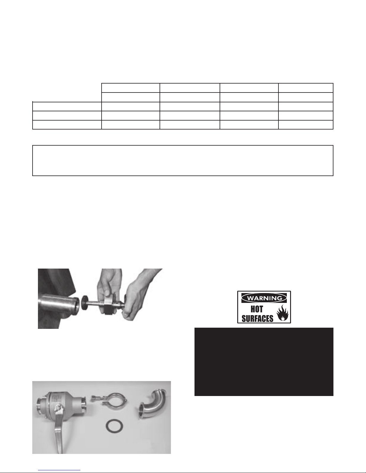
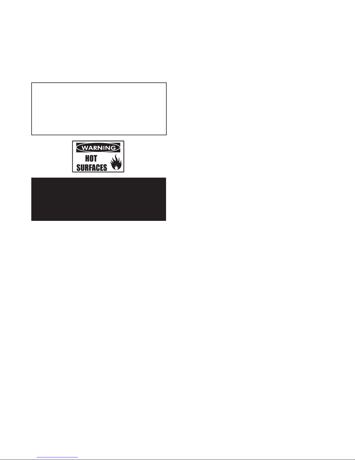
WARNING
OPEN THE KETTLE LID CAREFULLY TO
AVOID STEAM WHICH MAY ESCAPE.
DIRECT CONTACT COULD RESULT IN
SEVERE BURNS.
The following “action-reaction” outline is provided to
help the user understand how the equipment works.
When the operator starts up the kettle by turning the
operating thermostat dial from “OFF” to a desired
setting, the thermostat switch closes. This lights up
the heating indicator light and causes the contactors
to close, allowing power to flow to heating elements.
When the temperature of the steam jacket reaches
the value corresponding to the dial setting, the
thermostat switch opens. This turns off the heating
indicator light and causes the contactors to open,
cutting the power to the heaters.
As soon as the thermostat senses that the kettle is
cooling below the set point, the thermostat switch
closes, the heating indicator light comes on, the
contactors close, and the heaters come on again.
On-off cycling continues, keeping the kettle at the set
temperature. This is why the heating indicator light
cycles on and off during normal operation.
If steam pressure greater than 30 PSIG is generated
in the jacket, the safety valve will open and relieve
the excess pressure.
If the jacket water level gets too low before the
heating elements overheat, the high-limit control will
open and shut off power to the elements until the
kettle cools.
Setting the operating thermostat dial to “OFF” shuts
down all control and heating circuits.
6.0 Sequence of Operation