GRS GraverSmith 004-895 User manual

GraverSmith™
OPERATION AND MAINTENANCE MANUAL
#004-895
IMPORTANT
Read these instructions BEFORE operating the machine.
There are a few things that must be done before
connecting the machine to any power source.
NOTICE
This machine requires clean, dry oil-free air. We suggest
using an oil free compressor. If your compressor is an
oil type, you MUST have an oil removal filter (coalescing
type) in the air supply line to this machine. If you are
unsure of this requirement, please call 800-835-3519
or 620-343-1084 and ask for Technical Services.
OIL CONTAMINATION IS NOT COVERED
BY WARRANTY.

INTRODUCTION
The GraverSmith fulfills the need for a cost-effective
machine capable of allowing rapid cutting and carving
of metal, stone, wood, ivory and many other materials.
The easily controllable features of the GraverSmith also
makes it an ideal tool for stone setting, stippling, matte
finishing on jewelry, stipple engraving on crystals and
more.
The GraverSmith acts on the principle of an air-powered
hammer capable of delivering controlled impacts at speeds
of 400-8000 strokes per minute (handpiece dependant).
A foot pedal controls the impact power in much the same
way the gas pedal works on a car. The wide range of
power and control allows the user to freely move from
light to heavy cuts. To realize the full capability of the
GraverSmith you need to become familiar with both the
operation and routine maintenance of your machine. This
manual is intended to help you master both the machine,
handpiece and the proper preparation of the graver.
GraverSmith
1 Rugged plastic carrying handle
2 Press type ON/OFF switch
3 5 micron filter and water trap
*NOTE: Will not remove oil from air
4 Air regulator with gauge
5 Handpiece port
6 Strokes per minute control
7 Compressed air supply IN
8 Compressed air supply OUT
9 Air input port (from filter)
10 Foot throttle port
2
3
4
6
5
1
8
910
7
FIG. 1 FIG. 2

MACHINE SET-UP
CONNECT AIR SUPPLY
GraverSmith recommends 1.4 CFM (40 liters/min.) at a
minimum 45 psi (3.1 bar). Maximum input is 125 psi (8.6 bar). We
encourage reducing the air pressure from the compressor with
a regulator to 45~60psi (3.1~4.1 bar) as this ensures a stable
air pressure supply. The compressed air must be clean, dry, and
oil-free. The lter supplied with each unit is a nal lter and is not
capable of removing large amounts of water, oil, or contaminants.
If the air supply has excessive water, oil, or contaminants, an
additional lter/water trap/coalescing lter should be installed
ahead of the unit. Be sure to clean/purge all lters and water
traps regularly. IMPORTANT: Never add oil to the compressed
air for the GraverSmith. Oil can foul internal parts and cause
erratic handpiece operation. If your compressor requires oil,
YOU MUST use Coalescing Filter (#004-579) to ensure this oil
does not contaminate your compressed air.
Decide where you want to locate
the machine on your bench. NOTE:
The machine must be in vertical
position - DO NOT lay on its side.
Next, decide where you would like
the air lter located. Make its location
readily accessible so it is easy to purge
moisture from the bowl. You may attach
the air lter to your machine, bench, or
wherever you desire. Keep the location
of the lter where you can see it and
easily maintain it. Here we show it
attached to the back right side of the machine (FIG. 2).
CONNECTING THE HOSES
If “push-to-connect” ttings are new to you, they are amazing. With
the AIR PRESSURE SHUT OFF, simply insert the hose all the way
into the tting opening –– it stays attached. To disconnect, press in
on the orange ring while gently pulling the hose out.
Locate the air input tting on the air lter. It is identied on the
air lter with the marking “N”. Connect your 1/4" OD (6,35mm)
air supply hose directly to the “push-to-connect” tting simply by
pushing the hose end inside the orange ring receiver (A). If your
air supply hose is larger than 1/4" OD you have two options. Use
a reducer, not supplied, and step the air hose size down to a 1/4"
OD (6,35mm), or replace the “push-to-connect” tting with the
included barbed tting and attach air supply hose.
Locate the 6' (1.82m) air hose (#044-069) and cut a 5 1/2"
(139mm) piece from it. NOTE: This is if you are going to locate the
Air Filter as described above. Connect this 5 1/2" hose to the air
outlet (FIG. 3-B) on the air lter, opposite the air input. Connect
the other end of that hose into the tting on the back of the
machine (FIG. 3-B) marked AIR INPUT on the label below it. Use
these same connections no matter where you locate the lter.
CONNECT FOOT THROTTLE
Place the foot throttle on the oor in a convenient position. Run
the hose to the back of the machine. If you need to “snake” the
hose through an opening on your bench, make sure the hose is
not pinched or kinked. Connect the hose from the foot throttle to
the “push-to-connect” tting above the label marked THROTTLE
CONNECTION (FIG. 3-C).
CONNECT ELECTRICAL POWER
IMPORTANT: The ROTARY VALVE is lubricated by air
passing through it. DO NOT RUN THE MACHINE UNLESS
AIR SYSTEM IS ON.
Connect the electrical power cord into the 24 Volt Converter Box
(FIG. 3-E). Plug the converter cord into the jack on the back of
the machine (FIG. 3-D). IMPORTANT NOTE: DO NOT USE
OTHER BRANDS OF 24 Volt Converters - DAMAGE WILL
OCCUR to the machine.
The power converter supplied with your machine will accept 120
Volt or 230 Volt. All that is necessary to convert power supply is
to use the 230 Volt adapter supplied in the accessory box. You
are ready to tune the handpiece.
FIG. 3
FIG. 2

OPERATION
STROKES PER MINUTE (SPM)
Stroke speed setting is a matter of personal preference and
experience. Generally speaking, lower speed settings are
preferred for some stippling, matting or staking functions. Try mid-
range settings for tasks requiring maximum power. Higher speeds
work best for ne, delicate cuts and to obtain the best nish.
The GraverSmith shows a range of 400 to 8,000 strokes per
minute. The calibrations on the dial are only approximate. Each
model of handpiece has a normal range of strokes per minute.
Operating outside this range can produce erratic operation at times.
HOW TO TUNE THE GRAVERSMITH
By “tuning” your machine, we mean adjusting the strokes per
minute and air pressure for optimum performance. TUNING
YOUR MACHINE PROPERLY IS THE SINGLE MOST
IMPORTANT OPERATION YOU SHOULD LEARN.
1. Turn ON your air
compressor and allow
the tank to ll. Wait for
the compressor to cycle
off and stop running.
2. Turn the GraverSmith
on and set the stroke
per minute dial
at 2300 and using the
regulator knob on the
front of the machine,
back the air pressure
down to 2 to 5 PSI (0.1
to 0.4 bar).
3. Hold the handpiece you
have selected to use
with the tool holder end
up (vertically) next to your ear FIG. 4).
4. WITHOUT depressing the foot control, SLOWLY increase
the air pressure until the handpiece begins to buzz. While
continuing to increase the air pressure, the handpiece will
vibrate, more air pressure will make it knock. Slowly add air
pressure and when the knocking barely stops and add 2 psi
(.13 bar), this is considered the perfect air pressure operating
range for any of the handpieces listed in the chart at the
bottom of the page.
Another method of tuning (although not as precise) is to use
the initial setting shown in the chart below. Set the Strokes
Per Minute dial to the Recommended Initial Setting. Set the air
regulator knob to the middle of the Normal Air Pressure Range
for the handpiece you are using. The goal is to use the least air
pressure possible that will properly operate the handpiece.
Remember, if the handpiece vibrates without depressing the foot
control, the air pressure is probably too low. If the handpiece
fades out at full throttle, the air pressure is probably too low,
or the strokes per minute is too high for that handpiece. The
handpiece should start to operate within 3/8" (9,525mm) of
depression of the foot control, if it doesn’t the air pressure is
probably too high. Always make small adjustments in air pressure
or strokes per minute, not large ones, until you are familiar with
your machine.
If you have “tuned” your machine properly, the handpiece will
operate smoothly and predictably. New operators often use too
much air pressure or the incorrect strokes per minute range.
This can make your machine difcult to control for ne work.
The GraverSmith has excellent control for the smallest stone
setting and the nest engraving. But, you must learn to “tune” the
machine correctly to achieve this ne control! After a while, you
can experiment with variations in air pressure and stroke speed
to suit your work preference.
HANDPIECE Tuning Chart
004-506 Large 800 - 2400 20 - 30 psi (1.4 - 2.1 bar) 1400 24 psi (1.6 bar)
004-508 Standard 1000 - 2800 18 - 23 psi (1.2 - 1.6 bar) 2000 20 psi (1.4 bar)
004-563 Bulino 1600 - 4000 19 - 23 psi (1.3 - 1.6 bar) 3000 20 psi (1.4 bar)
004-610 / 609 Hammer 1000 - 2700 20 - 25 psi (1.4 - 1.7 bar) 1800 22 psi (1.5 bar)
004-710 Hammer 1000 - 2700 20 - 25 psi (1.4 - 1.7 bar) 1800 22 psi (1.5 bar)
004-801 / 810 1800 - 4000 21 - 25 psi (1.5 - 1.7 bar) 3000 22 psi (1.5 bar)
004-720 Heavy-Duty 800 - 2400 20 - 30 psi (1.4 - 2.1 bar) 1400 24 psi (1.6 bar)
Standard Spring 1400 - 3400 18 - 22 psi (1.2 - 1.5 bar) 2700 19 psi (1.3 bar)
004-901/9 10 - Fine Spring 1600 - 3600 12 - 15 psi (0.8 - 1.0 bar) 3000 13 psi (0.9 bar)
Standard Spring 2300 - 4000 11 - 14 psi (0.7 - 0.9 bar) 3600 12 psi (0.8 bar)
Fine Spring 2300 - 4000 5 - 9 psi (.34 - .62 bar) 3600 7 psi (0.4 bar)
004-940 Magnum 800 - 3400 20 - 23 psi (1.3 - 1.5 bar) 2400 21 psi (1.4 bar)
Normal Air
Pressure Range
psi (bar)
Normal
Operating Range
Strokes Per Minute
Recommended Initial Setting
Air Pressure
psi (bar)
Handpiece Type Strokes
Per Minute
004-921
Monarch
004-901 / 910
FIG. 4

HOW TO HOLD YOUR HANDPIECE
Normally, you should hold your handpiece like a table knife, not
like a pencil. A few exceptions are hammering and stippling.
Resist the urge to grip your handpiece tightly. Train yourself to
hold the handpiece as softly as you can. When you grip it tightly
or push hard with your hand, you lessen the impact power and
create more work for yourself. So,
relax and let the machine do the
work while you concentrate on the
design you are working on. When
you are doing heavy work, try this:
Partially release your grip on the
handpiece as you add more power
with the foot control. You will be
amazed at how much more power
you have. If you slip with the
graver, you are not operating your
handpiece properly, and probably
pushing too hard with your hand.
Hammering is a special situation.
When hammering you usually hold
the handpiece like a pencil. If you
are hammer setting, be sure to
press the hammer tip down rmly
on the work BEFORE using the
foot control to start hammering.
Also, do NOT operate the hammer
by holding the tip slightly above
the work as with many exible-
shaft hammers. Do NOT allow
the hammer tip to “bounce”
against the work. Use just enough
downward pressure to keep
the hammer from jumping off the work. GRS handpieces have
tremendous power. Use just enough power to do the work ... take
it easy at rst!
HOW TO USE THE FOOT THROTTLE
The GraverSmith foot throttle is operated like an automobile
accelerator and NOT like a exible-shaft foot control. You should
put the tool in position BEFORE depressing the foot control.
Never depress the foot throttle and then try to bring a stroking
handpiece to the work! If you need more power when cutting
deeper, push more on the
foot throttle to increase the
handpiece power. You will soon
learn to coordinate your foot
action with the need for more
power as you work. A beginner
will push the foot control down
a set amount and try to do the
rest by pushing the handpiece
harder, while never changing
foot position. This is incorrect
and not a safe way to use a handpiece. At the start of the cut,
increase power in a smooth fashion. If you need more power,
press more with your foot. As the cut tapers to the end, reduce
the foot pressure gradually as your hand tilts the graver up and
out. With a little practice, this hand/foot coordination will become
as natural as driving a car.
MAINTENANCE
IMPACT HANDPIECE CLEANING
DO NOT USE SOLVENT! The impact handpiece must be kept
clean for proper operation. If operation becomes sluggish, erratic,
or fails, follow these cleaning instructions.
Remove piston and spring from the handpiece. One at a time,
place in a sheet of writing or copier paper. DO NOT USE paper
towel, tissue, or newsprint. Holding it between your ngers (FIG.
5) “buff and polish” off any dirt or residue. Folding the paper, use
the edge to clean between the
piston grooves and the spaces
between the spring.
To clean the handpiece inside,
take the writing or copier paper
and twist it to a point (FIG. 6).
Insert the paper point into the
handpiece and rotate paper
and handpiece against each
other. This will “buff and polish”
the inside clean.
IMPORTANT NOTE: DO NOT
LUBRICATE PISTON, SPRING
OR BORE. Oiling: Occasionally
place a drop of synthetic oil or
light grease on the handpiece chuck
threads / jaws or Quick Change chuck. This will extend useful life,
and improve operation.
THROTTLE
The throttle should require little maintenance. It should be
cleaned periodically. Oiling: Periodically place a drop of oil on
the throttle hinges. When cleaning the oor, place foot throttle on
your bench or chair to prevent damage from debris.
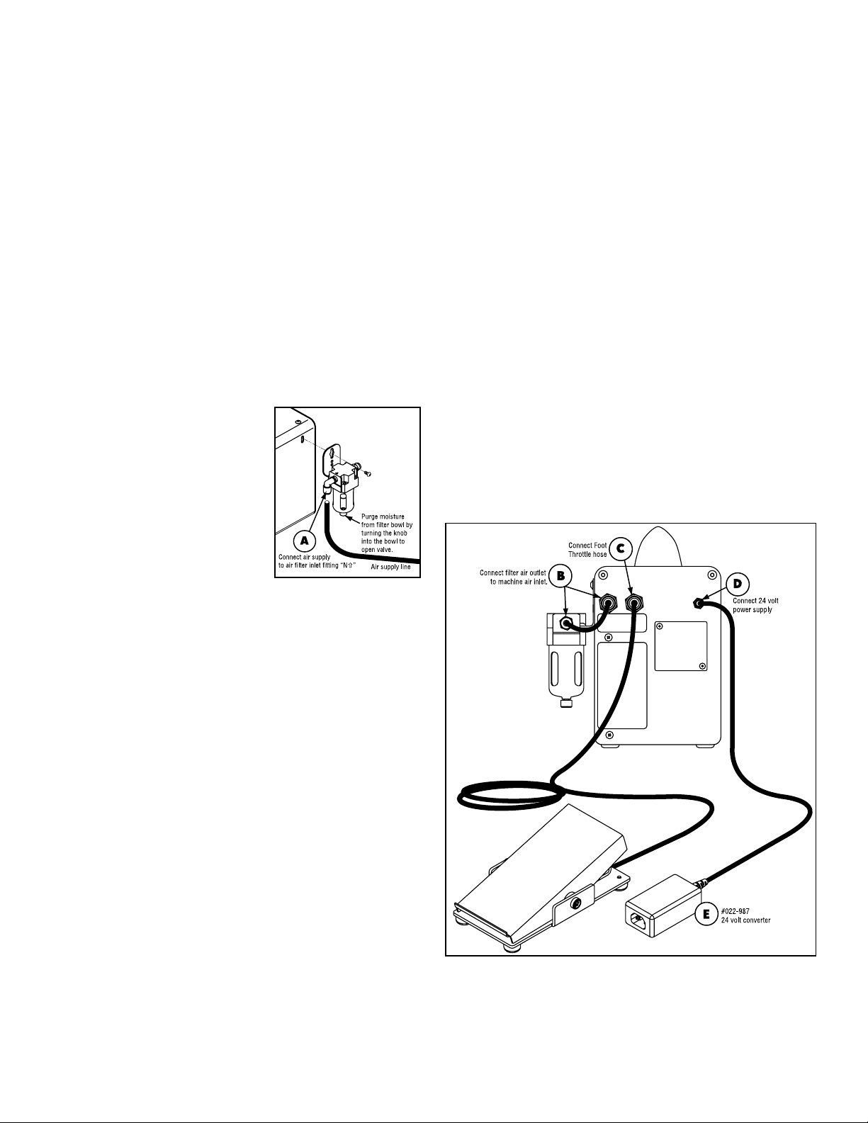
AIR SYSTEM
If large amounts of water and contaminants are in the air supply
to the unit, more frequent attention must be given to the units
lter. The bowl must be drained frequently to prevent water from
entering the rotary valve, hoses, handpiece, etc. In addition, the
lter element must be cleaned and / or replaced frequently. If
moisture is noted in the handpiece or throttle hoses, shut the unit
down immediately and drain the lter bowl, and then follow these
instructions:
1. Disassemble and clean impact handpiece(s) and reassemble.
2. Reduce pressure setting to 10 psi and turn unit ON to purge
moisture from valves, hoses, etc. - with handpiece not
attached.
ROTARY VALVE
The Rotary Valve is lubricated by air passing through it.
Additional lubrication is not required or recommended.
DO NOT RUN ELECTRICAL SYSTEM UNLESS
AIR SYSTEM IS ON.
FIG. 5
FIG. 5

TOOL INFORMATION
The ability to exercise precise control under all operating
conditions is the most important feature of the GraverSmith.
Coordination of the throttle and handpiece is very similar to
steering your car while depressing the gas pedal.
Place the cutting point of the tool in position before depressing
the throttle. Stop the stroking action before repositioning the tool,
or at the end of a cut.
Use sufcient impact force to perform the cutting with a minimum
of hand pressure. If your hand or arm becomes tired quickly, you
are pushing the tool. Use only enough hand pressure to maintain
complete control over the cutting action. If the tool point slips out
of position and gouges your work, you are using too much hand
pressure, or the point is improperly sharpened.
INSTALLING TOOLS INTO THE HANDPIECE
GRS offers a full line of graver,
points, and tools. GRS QC
Gravers are preshaped and
ready to be sharpened and used.
Standard gravers normally used with wood handles (point, knife,
liners, etc.) may be used in all handpieces. The tang (or shank)
end must be modied by grinding to t the chuck properly.
When inserting the desired tool into the chuck, it is not necessary
that it be aligned perfectly; however, it must be rmly seated
inside the chuck, on the face of the chuck, or on the ledge
provided in the chuck jaws.
The following sketch shows how the graver should be modied.
Do not use tool bits with a taper larger than the chuck will easily
accept. If the tool bit shank is so large that it will not “bottom out,”
the impact during use will wedge the tool into the chuck so tight
that it may damage it.
MORE ABOUT MODIFYING TOOLS
Removing the top/front of the engraver tip will allow a better view
of the area being cut and will permit faster sharpening as there is
less surface to be sharpened.
NOTE: When grinding a tool on a bench grinder wheel, do not let
the tool tip get too hot and burn. Burning means the tool metal
will turn blue, which takes the temper or hardness out of the tool
and it will not hold a cutting edge. To avoid burning the tool, do
not press too hard against the wheel; take your time. Have a
container of water that you frequently dip the tool into before it
gets warm in your hand.
Always be sure that the tool point is sharp. Refer to the TIPS
section for sharpening technique.
TOOL SHARPENING TECHNIQUES
While the GraverSmith is a tremendous aid in solving the most
difcult task in engraving or carving, it does not help in another
important area — the task of tool sharpening. In fact, it perhaps
even emphasizes that problem. You will be cutting faster and
deeper, and the need for proper point geometry and condition
will soon become apparent. Be prepared to go through a learning
period in tool sharpening. A few minutes spent with someone
who knows how to sharpen tools properly can save hours of
frustrating experimentation.
If a session with someone versed in tool sharpening is not
possible, read the following information and practice. In the end,
you must learn an effective technique so that when you put the
tool into the work, you know the result will be as you planned.
GRS Tools offers a Graver Sharpening Simplied Video
(#011-484) and a DVD called; The Expert’s Guide to Graver
Sharpening by Sam Alfano, Master Engraver (#022-375).
Various types of gravers
are used for different
types and styles of
cutting, but the square
and point (onglette) are
the most important in
metal cutting. Once you
master the sharpening
techniques for them, you
should have little difculty with others.
In his book, The Art of Engraving (#002-164), Mr. Meek’s
excellent illustration and discussion of the importance of proper
tool sharpening technique and geometry is especially helpful. He
relates to this subject in chapters 2, 4, and 7. This subject is of
utmost importance, and this reference material is very helpful.
Gravers should be ground on the face rst. An approximate
45-degree angle should be maintained. Keep the graver in the
handpiece for free hand sharpening. First, this will save time.
Second, the additional length provided is an aid in maintaining
the proper angle on the stone. A considerable amount of care and
practice is required to maintain the proper angle while sweeping
the tool point across the stone.
A common error in sharpening is the tendency to increase
the angle of the face
gradually each time the
graver is resharpened.
To help prevent this and
to reduce sharpening
time, it is helpful to
remove some of the
excess material near
the point with a
bench grinder.
GRS QC GRAVER
“READY-TO-GO” SHAPE

For the best results, the graver must be heeled, or set-up.
This task takes some experimentation and practice to produce
satisfactory results. The nish of the engraved cut is greatly
affected by the nish of the graver heel. For a bright cut, nish
the heel using polishing paper or a ceramic lap.
Here is what the heel accomplishes:
A. It raises the working angle of the graver to a convenient height
from the work surface.
B. It provides depth control.
C. It gives clearance when working on irregular surfaces and
prevents the bottom surface of the graver from dragging on
the edges of the cut when making curved cuts.
D. It improves the quality and appearance of the cut.
Usually a heel angle of 15 degrees is used. Only a small amount
of material needs to be removed. A few light strokes on a ne, hard
stone is sufcient. Don’t be confused by the tremendous number
and variety of gravers available in the supply catalogs; virtually all
work can be accomplished with a small variety of points.
FOR A COMPLETE LINE OF GRAVERS VISIT
THE GRS TOOLS GRAVER WEBSITE:
grstools.com/gravers-burs-and-more/
TIPS
The GraverSmith provides an effective, unique method for
performing a variety of functions in many materials. You may not
achieve effective results with the machine at rst. In fact, your
initial attempts may be disappointing or downright discouraging.
Begin by expecting a learning period, whether you have had
experience engraving by another method or are a novice. After
the initial learning period, the results and the satisfaction derived
from use of the machine are fantastic! It takes a little practice,
some learning, and perhaps some re-learning. It may seem
awkward and ineffective at rst — like your rst attempt to ride a
bicycle, remember?
The easiest and most productive way to learn quickly is to work
with someone accomplished in the use of the GraverSmith. If
this is not possible, the information contained in these “TIPS”
will be helpful. A most valuable and useful information source is
James B. Meek’s book, The Art of Engraving (#002-164) ... we
recommend it highly.
Most of the information in this section is directed toward the task
of metal engraving. Even if your purpose for using the machine
differs, this information is relevant and helpful. The engraving of
metal, especially steel, is most difcult, and demanding. When
the principles of metal engraving are understood, then other uses
will be less demanding. We have never known a person who
could effectively carve a deep relief scene that could not easily
set a stone, orentine or engrave a ring, matte nish a piece of
jewelry, or carve wood.
Here are some reasons why you may not achieve effective results:
• The concept of variable power applied to the handpiece
seems strange at rst.
• Coordination of power and tool cutting action with the foot
throttle might feel awkward, but after a small amount of
practice it will become natural.
• It seems strange and different at rst - but extremely effective
when mastered. Again, remember how easy it was to ride a
bicycle after you learned how. Successful cutting requires just
the right amount of forward pressure on the handpiece, and
proper manipulation of the throttle.
TECHNIQUES TO TRY
• Turn the machine ON, hold the handpiece in your hand, and
work the foot throttle to get the feel of the power variation
from light, short strokes to heavy, long strokes. You will begin
to anticipate the foot throttle position for the various power
settings desired.
• When cutting or engraving, hold the handpiece as you would
a table knife, not a pencil. Place your index nger on the
graver or chisel as you would on a knife blade to exert slight
downward pressure. Hold it like a pencil only when stippling,
background matting, chipping, etc.
• Place the tool cutting point on the work piece BEFORE
applying power with the throttle. Attempting to enter the cut
with the power ON and the handpiece stroking will quickly dull
or damage the tool point.
• Apply power with the throttle only AFTER positioning the tool
on the work. Use slight forward pressure to keep the tool point
moving forward into the cut. Both tool angle and downward
pressure control the depth of cut. Avoid using too much
downward pressure; it’s tiring and often indicates the need for
better tool sharpening or a more relaxed technique.
• Vary the power input with the throttle to control the speed and
depth of cut. Do not let the cutting action get ahead of your
ability to guide the tool. Stop the throttle action to reposition

the work. Leave the tool point in the cut.
• Overcome the tendency to let the handpiece continue to
stroke when not actually cutting (by failing to take your foot off
the throttle.) With practice, control of the throttle becomes an
automatic response.
• Use a stable vise or heavy engraver’s block to hold the
work. If the work is not held solidly, vibration will decrease
effectiveness of the tool’s power and will quickly dull or chip
the point. A GRS engraving block is a most effective work-
holding device.
• Don’t push hard! If your hand become tired or cramped, you
aren’t using the power of the machine to do the work, or you
may not have the tool properly sharpened or heeled.
• Keep the tool sharp and properly heeled. Sharpen frequently -
before you lose the point entirely. With practice you will begin
to “feel” when the point is beginning to dull. At this time, only
a slight amount of sharpening is necessary to bring it back
to the desired sharpness. Hardness of the material you are
cutting will greatly affect tool life.
• There should be no noticeable vibration of the tool point in the
cut. If the point is allowed to vibrate in the cut, the point will
dull quickly.
WORKHOLDING
The workpiece must be held as rmly as possible. If it is not,
much of the power and cutting capability of the tool is lost. Use
either an engraver’s ball vise or a vise which can be rotated with
your free hand to position the work as the cut progresses. GRS
offers a selection of vises to t different tasks.
GRS sharpening
equipment is a most
valuable aid in tool
sharpening. It is especially
helpful for beginners in the
art of engraving, and has
been readily accepted by
accomplished engravers
who have found that it is
faster and produces more
consistent results.
The combination of the GRS Power Hone®and the Sharpening
Fixture provides the ideal sharpening system. The Sharpening
Fixture is designed specically for use with the Power Hone. With
this combination, you can sharpen repeatedly with consistent
results time after time. It is easy to learn — you merely follow the
instructions.
Tips For Practice Sessions
Start with simple cuts. Using a square or point (onglette) graver,
begin by cutting straight lines then simple curves. Practice depth
control, cutting both ne shallow lines and deep cuts. It is good
practice to master the technique of varying the depth of cuts to
produce a pleasing shaded effect. These practice sessions will
help you acquire the necessary skills in both tool control and tool
sharpening techniques.
After you have mastered the basic skills, you can concentrate on
learning the more difcult and intricate designs. With condence
in your ability to control the tool, you will be able to execute
progressively more difcult patterns with varying depth of cut and
subtle shading, and nally on curved or irregular surfaces.
Simple exercises like those sketched below are good beginning
practice designs as they are relatively simple. It is easy to
determine the progression of the cuts to generate the design, and
they do not require a large amount of rotation or manipulation of
the work piece. This type of design is also good practice for the
beginning woodcarver.
Dual Angle
Sharpening Fixture
Ceramic lap
& diamond wheels
GRS Power Hone

GraverSmith™ Cover Assembly Parts List
002-062 #8-32 x 1/2 Rhms
002-064 Nut, #8-32 hex Z/P
002-104 Nut #8-32 HEXKEP Z/P
002-110 Washer, #8 PLTD
002-186 Pop rivet
022-230 90° push to connect fitting
022-231 Push-in male connector
022-248 8-32 x 7/16 pan head screw
022-944 5-micron filter & bowl
022-964 10-32 x 0.375" button head socket head screw
022-978 4m x 0.7 metric screw Phillips head
023-052 Rubber mounting foot
044-051 Filter mount
044-057 24v electrical label
044-059 Decal to identify air inlet port & exhaust port
044-143 Cover panel for GraverSmith
044-144 Formed base for GraverSmith
044-150 Molded handle
044-156 GraverSmith front decal
LIT-294 Oil contamination notice

022-230
022-948
044-006
004-951
044-161
022-965
022-965
022-965
044-157
044-160
044-158
023-051 022-230
022-230
044-159
024-169
024-170
044-255
024-168
002-536
022-230
022-230
GraverSmith™ Pneumatic Parts List
002-536 NUT, 1/4"-20 FLNG LOCK Z/P
004-951 VALVE BODY, ROTARY
022-230 FITTING, PTC 0.25" 90° M1/8" NPT
022-948 O-RING, 1.078" O.D. 0.938" I.D.
022-965 FITTING, PTC 0.25" BULKHEAD
023-051 ARG REGULATOR GAUGE IN KNOB
024-167 MOLDED AIR TANK (TWO HOLE VERSION) - 1
024-168 SPECIAL WASHER - 3
024-169 O-RING - 1
024-170 SOCKET HEAD CAP SCREW - 3
044-006 VALVE SHROUD, ROTARY
044-157 6.0" LENGTH OF 050-029
044-158 8.8" LENGTH OF 050-002
044-159 8.6" LENGTH OF 050-002
044-160 12.60" LENGTH OF 050-002
044-161 10.6" LENGTH OF 050-002

GraverSmith™ Electrical Parts List
002-068 Set screw #10-32 x 1/4" blk
002-104 Nut #8-32 HExKEP Z/P
004-812 Speed pot wire assembly
004-817 Red wire assembly motor to control
004-817 Red wire assembly switch to control
004-818 Black wire assembly switch to control
004-826 Power jack assy For GraverSmith
004-827 Red wire assembly switch
004-828 Black wire Switch
004-829 Ground wire assembly heatsink to board mount screw
022-961 4000 rpm motor
022-962 Controller board
022-968 6-32 x 0.375 round head machine screw
022-970 24VDC green illuminated switch
022-990 Nylon washer
023-053 Isolation mount
023-054 Control knob rogan PT-6-PS
044-040 Valve rotor
044-043 Flywheel for valve rotor
044-145 Motor mount mass plate

GraverSmith™ Boxed Items Parts List
PART NO. DESCRIPTION
002-115 Square point graver
002-361 Barb fitting, 1/8 x 1/4
002-979 Steel point, small
004-050 6 ft. of #050-002 for foot control
004-519 Throttle assembly
022-053 Hex wrench, 1/8” Hex Key
022-404 #4 QC HSS Onglette Graver
022-872 Schuko adaptor 110 to euro 230
022-987 Power supply
022-993 115 power cord assy
044-069 6 ft. #050-029 black supply tube
WARRANTY
Each GraverSmith, including handpieces and foot control, carries a full 2-year
warranty covering parts and labor.
These products are designed for reliable operation using most sources of
compressed air. However, some air supplies contain excessive water, oil,
dirt, rust, or other contaminants. The unit’s built-in lter is a nal lter to
protect against normal dirt and water. If your compressed air has excessive
contaminants, you should install the necessary lter(s) and water trap(s) ahead
of your unit.
Oil contamination can be gradual and subtle. If you notice an oil residue (usually
a yellow to brown colored sticky or liquid residue) in the unit’s lter bowl or
handpiece / throttle hose, you probably have an oil problem in your compressed
air. Older oil-lubricated and “silent” compressors that use internal oil are more
likely to cause oil contamination. If this occurs, install a Coalescing Oil Filter
(GRS #004-579 or equivalent).
NOTE: Damage caused by contaminated compressed air is not covered by
the warranty.
Glendo Corporation
900 Overlander Road
Emporia, KS 66801 USA
Toll-Free: 1-800-835-3519
Phone: 620-343-1084
Fax: 620-343-9640
E-mail: [email protected]
www.grstools.com
GraverMach, GraverMax SC, GraverMax,
GraverMate, GraverSmith, BenchMate,
and Power Hone are registered
trademarks of Glendo Corporation.
USA and foreign patents
Printed in USA
All rights reserved.
© 2008, 2011 Glendo Corporation
Last Update: FEB 2011
LIT-307
Foot Throttle #004-519 Parts List
PART NO. QTY. DESCRIPTION
001-028 2 Throttle Hinge Nut
001-036 1 Throttle Spring
002-065 2 10-32 x 3/8” RHMS
002-073 2 1/4-28 Nu
002-204 1 10-32 Hex Whiz Loc Nut
002-247 1 Washer
002-517 1 1/8” NPT x 0.170” Barb Fitting
002-526 1 Spring Retainer
002-527 1 10-32 x 3/4” RHMS
004-006 1 Throttle Base
004-007 1 Hinge Plate
004-008 1 Spring Retainer
004-009 2 Spacer
004-010 1 Pivot Shaft
004-011 1 Bleed Shaft
004-012 1 Outlet
004-031 1 Throttle Outlet Spring
004-459 1 Spring Retainer
011-210 4 Rubber Foot Assy. 8-32 x 3/8”
022-170 1 1/4-40 x 3/16” SHSS
022-553 1 10-32 x 1/4” RHMS
Table of contents
Other GRS Engraver manuals