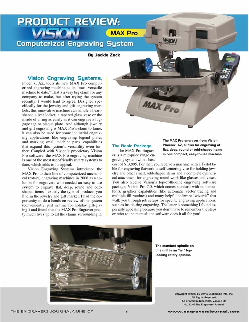
Vision MaxPro User manual

Operations Manual
Vision Engraving & Routing Systems
17621 N. Black Canyon Hwy.
Phoenix, AZ 85023
www.visionengravers.com
Vision MaxPro

All rights reserved. No parts of this work may be reproduced in any form or by any means - graphic, electronic, or
mechanical, including photocopying, recording, taping, or information storage and retrieval systems - without the
written permission of the publisher.
Products that are referred to in this document may be either trademarks and/or registered trademarks of the
respective owners. The publisher and the author make no claim to these trademarks.
While every precaution has been taken in the preparation of this document, the publisher and the author assume no
responsibility for errors or omissions, or for damages resulting from the use of information contained in this document
or from the use of programs and source code that may accompany it. In no event shall the publisher and the author be
liable for any loss of profit or any other commercial damage caused or alleged to have been caused directly or
indirectly by this document.
Printed: September 2006 in USA.
Vision MaxPro
© 2006 Vision Engraving Systems
(A division of Western Engravers Supply, Inc.)

IContents
I
© 2006 Vision Engraving Systems
Table of Contents
Part I Before you begin 2
...................................................................................................................................2About This Manual
...................................................................................................................................2Safety
...................................................................................................................................3Unpacking and Taking Inventory
...................................................................................................................................4Specifications
Part II Configuration 8
...................................................................................................................................8Cabling the MaxPro
...................................................................................................................................10Configuring the PC
.......................................................................................................................................................... 10Using a Network Connection
......................................................................................................................................................... 10Direct to the PC
......................................................................................................................................................... 11Through a Network
.......................................................................................................................................................... 11Using a Serial Connection
.......................................................................................................................................................... 12Configuring Windows
......................................................................................................................................................... 12Windows XP
......................................................................................................................................................... 15Windows 2000
......................................................................................................................................................... 18Windows 98
...................................................................................................................................20Configuring the Software
.......................................................................................................................................................... 20Installing Job Server
.......................................................................................................................................................... 31Installing Vision Pro/Vision Pro LT
.......................................................................................................................................................... 40Configuring Vision Pro/Vision Pro LT
...................................................................................................................................46Table setup
.......................................................................................................................................................... 46T-Slot table .......................................................................................................................................................... 48Vice .......................................................................................................................................................... 51Rotary .......................................................................................................................................................... 53Using Water ......................................................................................................................................................... 53Filling the Reservoir
......................................................................................................................................................... 54Adjusting the flow
Part III Operations 58
...................................................................................................................................58Starting the Job Server
...................................................................................................................................60Hand Held Pendant
.......................................................................................................................................................... 60Buttons .......................................................................................................................................................... 68LCD Display
...................................................................................................................................76Operations and Lessons
.......................................................................................................................................................... 76Selecing machine drivers
.......................................................................................................................................................... 79Holding Flat Items with the T-Slot table
.......................................................................................................................................................... 82Lesson 1 - Engraving a Small Name Badge
.......................................................................................................................................................... 88Lesson 2 - Engraving Pens
.......................................................................................................................................................... 95Lesson 3 - Engraing Round objects
.......................................................................................................................................................... 106Lesson 4 - Engraving Luggage tags
.......................................................................................................................................................... 115Lesson 5 - Engraving Rings and Bracelets
.......................................................................................................................................................... 134Advanced Text Options


Vision MaxProII
© 2006 Vision Engraving Systems
.......................................................................................................................................................... 155Multiple Plates
.......................................................................................................................................................... 162Scanning and Graphic editing
.......................................................................................................................................................... 171Creating Custom Vision Pro Drivers
Part IV Maintenance 180
...................................................................................................................................180Lubrication
...................................................................................................................................184Changing the Motor Belt
...................................................................................................................................185Draining and Cleaning the Water Resevoir
...................................................................................................................................186Cleaning the vice rail and lead screw
Part V Troubleshooting 188
...................................................................................................................................188Job Server
Index 197

Chapter I

Vision MaxPro2
© 2006 Vision Engraving Systems
Before you begin
About This Manual
This Manual is designed to provide you with information about the "Multi Axis Professional
Engraver" or "Vision Jeweler" machine (referred to as the MaxPro in this manual), beginning
with unpacking the machine, setup, operations and maintaining the machine. Some

previous knowledge of engraving terms and the engraving process is assumed. For
information on the Vision Pro Engraving Software, see the software manuals that came with
it. For more information on your individual computer system, see your computer’s user
manual or contact your computer distributor.
Safety
Safety Precautions for the MaxPro Engraver.
ØKeep hands clear of the bottom of the spindle, the motor belt and the spindle pulley during
operation.
ØAlways stop the machine before making any adjustments.
ØDo not operate the machine with the covers removed.
ØWear safety glasses when cutting any materials that emit chips.
ØUse extreme caution when inserting or removing cutters.
ØBefore any servicing, disconnect the power cord to the controller and the table cables.
ØTo avoid electric shock or equipment damage, ensure that the control unit is connected to
the appropriate electrical source as noted in the installation procedures.
ØNever operate the equipment with damaged or frayed power cords, loose connections or
exposed extension cords where someone can step on the cord and create a tripping
hazard.
ØBe sure to hold the plug, not the cord, when disconnecting the controller from an electrical
socket or power source.
ØPlace the machine in a location with low humidity and a minimum of dust. Avoid placing
the equipment in direct sunlight or in locations with excessive heat.
ØIf you machine does not operate properly; in particular, if there are any unusual sounds or
smells coming from it, immediately unplug it and contact a service technician or your local
distributor.
ØUnplug the machine when it is going to be left unused for an extended period of time.
ØOpenings are provided on the bottom of the machine for ventilation. Do not cover the
openings or place the controller in an environment where the openings may become
blocked.
ØNever insert anything into the ventilation openings. Doing so may create a danger of
electric shock.
ØDo not expose the control unit to rain or use it near water. You can clean the controller
with a damp cloth but be sure to unplug the unit first.

Before you begin 3
© 2006 Vision Engraving Systems
Unpacking and Taking Inventory
The MaxPro engraving system has been shipped in one crate, unless other accessories
have been ordered with the machine that will not fit in the crate. Examine the condition of
the crate for external damage. In the event of apparent external damage, notify your
shipping carrier upon receipt, and call your sales representative or Vision immediately.
Note: The shipping container is considered reusable and should be stored for use in the
event of service need or upgrade.
Step1:
Take the top lid of the crate off by removing the Phillips screws in the top. Remove the
sides of the crate by removing the Phillips screws on the sides. Remove the two wood
pieces that are screwed into the base of the crate. The machine can now be removed. In
the crate will be a cardboard box with all of the machine accessories (including this manual).
Open the accessory box and the following items should be included:
Ø1 Hand held pendant
Ø1 Vision warranty card
Ø1 This MaxPro manual
Ø1 Vision All Products CD
Ø1 Vision Pro or Vision Pro LT USB software dongle (if purchased)
Ø1 Vision Pro/Vision Pro LT dongle information sheet
Ø1 Network cable
Ø1 Network crossover adaptor
Ø1 Serial cable (null modem)
Ø1 Power cord
Ø2 Spare 8 amp fuses (DC)
Ø2 Spare 10 amp slow blow fuses
Ø1 Quick lock vice (mounted on the T-Slot table)
Ø1 Cutter wrench
Ø1 Spare 10 1/2" motor belt
Ø1 Engraving cutter .015" tip
Ø1 Engraving cutter .030" tip
Ø1 Non rotating diamond cutter
Ø1 Allen wrench set
Ø1 Water nose cone
Ø1 Cone drive
Ø1 Tail stock

Vision MaxPro4
© 2006 Vision Engraving Systems
Ø1 Medium cone
Ø4 Small dowel pins
Ø4 Small button head screws
Check to see that all of the items are included. Should any of the contents be missing,
damaged, or of the incorrect type, please call your sales representative or Vision
immediately.
If the Vision Platinum Jewelry package was purchased, the items below are included also in
addition to the items above.
Ø1 Computer (Desktop or Laptop)
Ø1 Scanner
Ø1 Ring Gauge
Ø1 Digital Calipers
Ø1 Ring Attachment
Ø1 Rotating diamond cutter .005 tip
Ø1 Rotating diamond cutter .015 tip
Ø2 Burnishing Adaptors
Ø1 Universal Pin Fixture
Ø1 Adjustable Pen Fixture
Ø1 Universal Clamping Bars w/Medallion Holder
Ø1 T-Handle Allen Wrench 3/32"
Ø1 Gold Rub n Buff
Ø1 White Rub n Buff
Ø1 Silver Rub n Buff
Step 2:
Prepare a clean, level surface to put the engraving machine on. Carefully lift the machine
out of the crate and place it on the table.
Step 3:
After unpacking the machine, make sure that you SAVE THE CRATE, FOAM PACK and
ANY OTHER BOXES. They can be reused in the event the system must be transported to
another location or returned for service. Improper packaging for shipment can damage the
machine and may void the warranty.
Specifications
Z-Axis stroke/clearance:
3 inches (75 mm)

Before you begin 5
© 2006 Vision Engraving Systems
Table resolution:
.0002 inch
Engraving area one pass:
8“ x 12 ” (203 mm x 304 mm)
Engraving area maximum:
14“ x unlimited12 ” (355 mm)
Rotary engraving maximum size:
6“ diameter x 12" tall (152 mm x 304mm)
Work holding vice: Self-centering vice with pins for holding various clamps
Spindle speed:
3,000 to 16,000 adjustable RPM
Tilt angle:
15 degrees maximum
Power requirements:
110 or 220 volts, 10 amp
Laser pointer:
640 nanometers, <.5 milliwatts
Water system:
Self contained, recirculating pump (for engraving glass)
Overall Dimensions:
26 1/2” Tall x 28“ Wide x 28” Deep (673 mm x 711 mm x 711 mm)

Vision MaxPro6
© 2006 Vision Engraving Systems
Shipping dimensions:
41" x 33" x 39.5" (1041mm x 838mm x 1003mm)
Machine weight:
150 lbs.
Shipping weight:
325 lbs.

Chapter II

Vision MaxPro8
© 2006 Vision Engraving Systems
Configuration
Cabling the MaxPro
Please connect the cables to the back of the MaxPro machine per the instructions below.
Locate the table cable connection box shown in figure 2.1 below.
(Figure 2.1) The table cable connection box
Plug the 25 pin cable into the table cable connection box as shown in figure 2.1 above. The
connector is labeled number 1. Make sure to tighten the two table cable tightening screws
shown. Caution: Do not over tighten these screws.
Connect the remaining cables per figure 2.2 below. A description of each connection is
below.
(Figure 2.2) The Vision Serial Controller connections

Configuration 9
© 2006 Vision Engraving Systems
1. Connect the hand held pendant cable to the position labeled 1 in figure 2.2. Make sure to
tighten both screws in the plug securely.
2. Connect the supplied network cable to the plug labeled 2 in figure 2.2 Please see the
next section in this manual labeled ‘Using a network connection’ for information on how to
connect the other end of this cable to your PC.
3. Plug 3 in figure 2.2 is used only in the event that no network connection is available to use
the engraver with. In this case, use the supplied 9 pin female to 9 pin female null modem
cable to connect from the MaxPro to your computers serial port. Note: This is only used if
you are NOT using the network connection on the MaxPro.
4. Looking from the back side of the machine, plug in the large cable from the right upright
into the plug labeled 4 in figure 2.2. This is used for the rotary axis motor and vice motor.
Make sure to tighten both screws in the plug securely.
5. Connect the 25-pin cable to the plug labeled 5 in figure 2.2. This cable connects the
entire head of the machine to the electronics tray. Make sure to tighten both screws in
the plug securely.
6. Number 6 in figure 2.2 is the DC fuse holder. If this fuse were to blow, replace it with an 8
amp fuse.
7. Number 7 in figure 2.2 is the AC fuse holder. If this fuse were to blow, replace it with a 10
amp slow blow fuse.
8. Number 8 in figure 2.2 is the on/off power switch.

Vision MaxPro10
© 2006 Vision Engraving Systems
9. Number 9 in figure 2.2 is where the 110 volt power is plugged into. Note: 220 volts can
be used if the machine is configured to accept 220 volts. There is typically a yellow label
near the plug if the machine is configured for 220 volts.
10. Looking from the back side of the machine, plug in the small cable from the right upright
into the plug labeled 10 in figure 2.2. This is used to power the water pump.
11. Connect the thin gray auxiliary plug (extending from the auxiliary power box) to the plug
labeled 11 in figure 2.2. (Note: This is an optional auxiliary power box used only with a
vacuum chip removal system. If a vacuum chip removal system is not required, there is
no need for the auxiliary power box).
The MaxPro Engraver is now connected properly.
Configuring the PC
Using a Network Connection
There are two different types of network connection methods that can be used for the
MaxPro Engraver. Connect the supplied network cable to the network plug on the back of
the MaxPro. The other end of the network cable connects in one of two ways.
Direct to the PC
If you are connecting the MaxPro directly to a PC and not through a network server, please
attach the supplied network crossover adaptor to the end of the network cable. Then plug
the adaptor directly into the network connection in the back of your PC. The IP address will
need to be manually entered into the Vision controller. To do this, follow the steps below:
1. Turn the MaxPro on. After a few seconds, the machine will boot up.
2. Press the Menu button on the hand held pendant.
3. Press the Y down jog button ten times.
4. The cursor will be on Ethernet Settings. Press the Enter button on the pendant.
5. The cursor will be on Specify IP. Press the Enter button on the controller.
6. Press the EXIT button on the controller to specify an IP address.
7. Using the number pad on the pendant, type 192 and press Enter.
8. Type 168 and then Enter.
9. Type 5 and then Enter.
10. Type 101 and then Enter.
11. The Enter NetMask screen will show on the LCD screen. Type 255 and then Enter.
12. Type 255 and then Enter.
13. Type 255 and then Enter.
14. Type 0 and then Enter.

Configuration 11
© 2006 Vision Engraving Systems
15. Press the Exit button on the controller two times. The IP address is now set in the
MaxPro.
Through a Network
If you are connecting the Vision controller to a network server, plug the network cable
directly from the MaxPro into a network port. When the machine is turned on, it will
automatically receive an IP address from the network server it is connected to.
If the network is not setup to assign an IP address to the MaxPro, one can be entered
manually into the machine. Please follow the steps below.
1. Turn the MaxPro on. After a few seconds, the machine will boot up.
2. Press the Menu button on the hand held pendant.
3. Press the Y down jog button ten times.
4. The cursor will be on Ethernet Settings. Press the Enter button on the pendant.
5. The cursor will be on Specify IP. Press the Enter button on the controller.
6. Press the EXIT button on the controller to specify an IP address.
7. Using the number pad on the pendant, type 192 and press Enter.
8. Type 168 and then Enter.
9. Type 5 and then Enter.
10. Type 101 and then Enter.
11. The Enter NetMask screen will show on the LCD screen. Type 255 and then Enter.
12. Type 255 and then Enter.
13. Type 255 and then Enter.
14. Type 0 and then Enter.
15. Press the Exit button on the controller two times. The IP address is now set in the
MaxPro.
Note: You will need to ask your network administrator for the numbers to enter in steps 7
through 10 above. Entering the incorrect numbers will not allow the MaxPro to run through
the network.
Using a Serial Connection
If you cannot connect the Vision controller to the PC through a network connection, you can
use a serial connection. Connect the 9 pin female to 9 pin female null modem cable from
the Vision controller to your computers serial port shown in figure 2.3.
(Figure 2.3) The PC serial connection

Vision MaxPro12
© 2006 Vision Engraving Systems
Configuring Windows
When using a network connection through a network server, there is no configuration
required with the PC so you can skip this section. If you are connecting the Vision controller
directly to the PC using a network connection, you must configure the Windows© network
settings. The settings are different depending on which version of the Windows© operating
system you are using. Please follow the instructions below for the correct version of
Windows© is on your PC.
Windows XP
1. If there is a My Network Places icon on your main Windows© screen, go to step 3 below.
2. If there is no My Network Places icon on your main Windows© screen, click on the Start
button at the lower left corner of the Windows screen.
3. Right click on My Network Places and go to Properties.
4. Right mouse click on the Network Connection in the right side and select Properties.

Configuration 13
© 2006 Vision Engraving Systems
5. Highlight the Internet Protocol (TCP/IP) and click on Properties.

Vision MaxPro14
© 2006 Vision Engraving Systems
6. Select “Use the following IP address:”. Enter the numbers shown below for the IP
address and Subnet mask.

Configuration 15
© 2006 Vision Engraving Systems
7. Click OK and the click Close.
Windows 2000
1. Right click on My Network Places from the Windows© desktop and go to Properties.
2. Right mouse click on the Network Connection in the right side and select Properties.

Vision MaxPro16
© 2006 Vision Engraving Systems
3. Highlight the Internet Protocol (TCP/IP) and click on Properties.
Table of contents
Other Vision Engraver manuals

Vision
Vision VE-810 User manual

Vision
Vision PHOENIX TABLE User manual

Vision
Vision MAX Pro User manual

Vision
Vision VE810 S5 User manual

Vision
Vision Phoenix 1212 User manual

Vision
Vision MAX Pro User manual

Vision
Vision Phoenix 1212 S5 User manual

Vision
Vision VE810 4 Series User manual

Vision
Vision Cylindrical User manual

Vision
Vision Multi Axis User manual