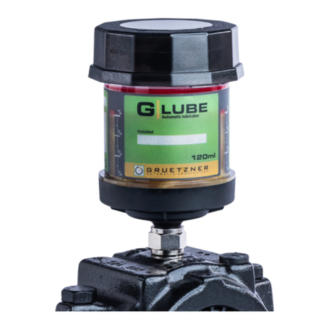
Gruetzner Lubricus LUB-D1 User manual

version 04/2013
User Guide
Lubricus Lubrication System
LUB-D1/LUB-D2/LUB-D3/LUB-D4
(24 VDC)

2
Content
General Information 3
Warning 3
Scope of Supply 3
Overview 3
General safety details 4
Intended use 4
Extent of warranty 4
General safety information 4
Transport and storage 6
Function /Principle 7
Communication Interface, Connector PIN assignment 7
Installation instruction/ Pulse signals details 8
Functional problems: error, message and problems 9
Service: replacement of cartridge 9
Technical Data 11
Recommended tube length 11
Mounting 12
Disposal 12

3
General Information
Thank you very much deciding to use Lubricus Lubrication System. Make sure that you familiarize yourself with the safety
instructions of Lubricus Lubrication System and the accessories supplied with this unit. This manual contains important
safety information.
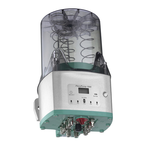
The Lubricus Lubrication System is a very compact lubrication pump for oil and grease up to NLGI 2. The pump requires 24
VDC power supply. The lubricant reservoir (400 cm³) is contained in cartridge. Supply pressure is up to 70 bar (1,000 psi).
The Lubricus Lubrication System Type D is available with up to 4 outlets.
Warning
Lubricus Lubrication System is designed for use in normal industrial environment indoor as well as outdoor but is not suitable
for mounting on moving equipment for example trucks. Only use original Lubricus cartridge and original spare parts. None
original spare parts can destroy the Lubricus Lubrication System.
Scope of supply
Standard delivery includes:
-Lubricus Lubrication System
-Tube connector attaches to the outlet, suitable for flexible tube 6 x 4
-(Ø 6mm outside and Ø 4mm inside diameter),
-Operating Instructions
Overview
The setup of your - Lubricus Lubrication System is easy. This user manual will learn you the basic operation and
adjustments.
Important remark: unused outlets must remain open to avoid damage to the pump!
Ventilation Lock
Housing
Connection M12x1 external control
outlets

4
Attention!
General safety details
Everybody who is involved with the installation, start-up, maintenance and operation of the Lubricus Lubrication System must
read these instructions carefully!
Use in accordance with guide
Lubricus Lubrication System is only allowed for industrial use.
Lubricus Lubrication System may only be put into service, if it is integrated or attached to another
machine and will be operated together with that machine.
Lubricus Lubrication System may only be used according to the technical data (see chapter
“technical data”)
Unauthorized structural changes at the Lubricus Lubrication System are not permitted. We do
not assume liability for damages of persons or machines which result from that.
Additional directives for use in accordance with the regulations:
•Pay attention to all notes in the operator’s manual / user guide.
•Carry out all maintenance work.
•Follow all appropriate regulations for the work safety and accident prevention during life of the Lubricus Lubrication
System.
•Only qualified and authorized personnel can carry out required work on the Lubricus Lubrication System.
Other uses or uses beyond those described above cannot be considered to be in accordance
with the regulations.
Extent of warranty
Warranties concerning operating safety, reliability and capacity, are only granted under the following conditions:
Assembly, installation, maintenance and repair are only carried out through trained specialist. Hazardous hot or cold
machine parts must be shielded to prevent touching.
-The Lubricus Lubrication System must be used according to the instructions in the technical operating manual
-The rated technical data must not be exceeded in any case.
-Retrofitting and repair work on the Lubricus Lubrication System may only be done by the manufacturer.
General safety information
Basic information, which must be followed during service, operation and maintenance, are listed as follows.
It is absolutely essential to read the operator’s manual / user guide by respective technical staff / technical operator before
installation and start up. In addition to this, it must be permanently available at the site.
IMPORTANT
Please pay attention, not only to the safety instructions under this main point, but also to those special security cautions that
are mentioned on the other pages.
This symbol warns of electrical voltage.
Attention!

5
Remark!
Attention!
This heading is used if inaccurate compliance or non-compliance with the operating Instructions or
specified work procedures etc. may result in damage.
Points out special information.
Notes attached directly on the machine, must be strictly followed and maintained in completely readable
condition!
Qualification and training of the personnel
The operation, maintenance, service and installation personnel must have appropriate qualifications for this
work. Responsibility and supervision of the personnel must be clearly defined by the end user / operator. If
the personnel do not have the necessary knowledge, they must be trained and instructed. The operator must
ensure that the personnel have completely understood the contents of the user information.
Non-observance of the safety information can be dangerous
Not observing the safety information can lead to danger for people, environment and machines.
Not observing the safety information can mean the loss of any or all damage claims. In special cases, non-
observance can, for example, lead to the following dangers:
•Failure of important plant functions.
•Failure of prescribed methods of maintenance and preventive maintenance.
•Endangering people due to electrical, mechanical and chemical effects.
•Endangering the environment due to leaks of dangerous materials.
Safety information for operators/operating staff
•Hot or cold machine parts are hazardous and must be protected from touching. The protection on
"moving or rotating parts" must not be removed.
•In case of leakages of dangerous media proper disposal not endangering environment and people must
be ensured.
•Legal Regulation must be observed and complied.
Eliminate any danger due to electrical power.
Safety information for maintenance, inspection and assembly work
All maintenance, inspection and installation work may only be carried out by trained specialists who
have been informed appropriately by studying the user information closely.
All work must only be carried out when machine is shut down and while wearing appropriate protective
clothing. Always comply with the procedures for shutting the machine down that are described in the
operating manual. All the safety and protective equipment must be replaced immediately after completing
work. Environmentally hazardous substances that endanger the environment must be disposed in
accordance with local regulations. Secure the system during maintenance and repair work, against
intentional or unintentional operation. Dispose of used lubricants in accordance with the safety data sheets of
the lubricant manufacturer.
Alterations and manufacture of spare parts without authority
Rebuilding or altering the Lubricus Lubrication System is only allowed after consultation with the
manufacturer. Original spare parts and accessories authorized by the manufacturer are for safety
purposes. Using other parts results in loss of liability for claims resulting out of this. For components,
retrofitted by the operator, the manufacturer does not assume guarantee nor claims for damages.
6
Prohibited methods of operation
Operational security of the Lubricus Lubrication System is only guaranteed if it is operated in accordance with the
operating instructions. The limit values stated in the technical data must not be exceeded under any circumstances.
General risk reference
All components of the system are designed in accordance with the prevailing regulations of the construction
of technical machines, in regards to operational safety and accident prevention. Operation outside of these
constraints can lead to dangers for the user respectively third persons or other technical facilities. The
Lubricus Lubrication System therefore may fulfil only in technically fault-free condition its intended use.
This may only be carried out under compliance of the safety regulations and the attention of the operator's
manual.
Therefore please regularly inspect the pump and its attachments for possible damage or leaks.
Transport and storage
Use suitable lifting gear for transport.
Do not throw or expose the Lubricus Lubrication System to strong shock loads.
Store the Lubricus Lubrication System in a cool and dry place to avoid corrosion of the system’s individual parts.
Pay attention to the current safety- and accident prevention instructions during the transport. Wear suitable
protection equipment if necessary!
Installation instruction
The following conditions have to be satisfied during the installation of this Lubricus Lubrication System, thus it
can be assembled, with other parts, to a complete machine without affecting the safety and health of
humans.
The housing of Lubricus should not be exposed to direct sunlight and/or radiant heat preventing the
formation of condensation.
Electrical connection
•Have the electric power supply connected only by a trained electrician!
•Connection and wiring of the electric components should be done by an expert trained in this field.
•Check the voltage details with the existing power supply voltage!
Maintenance /repair
Disconnect the voltage feed, before starting with maintenance or repair.
Maintenance and repair work may only be done with the system shut down.
Check the surface temperature of Lubricus Lubrication System, due to danger of burning by radiant heat.
Always wear heat-resistance gloves! Protect the system from activation during maintenance and repair work!

7
Function/Principle
When you activate Lubricus, Type D, the piston pump starts to work and pump the lubricant in small quantities to the outlets.
The integrated microprocessor controls the function. Communication with the machine controller is necessary. Delivery rates
and time between the lubrication intervals can be individually set by pulse signals.
The Lubricus Lubrication System uses a four-pin socket to connect a M12X1 plug allowing communication with the machine
controller. An external 24 VDC power supply is used to switch ON and OFF (voltage of +20 ....up to +30 VDC, supplied to
PIN 1). When voltage is supplied the lubrication pump is in operating condition. If there are no errors (Pump OK) the input
voltage will be transferred to the output signal (PIN 4) indicating all is OK. Once the voltage supply to PIN 1 is stopped
(switched OFF), the pump rests and saves the current operating conditions in memory. When the pump is turned back on the
saved operating conditions will be continued. PIN 4 relays the operating condition.
Connector PIN assignment, connection to Lubicus, Type D
Output signal: in case of empty lubricant reservoir: PIN 4 generates an alternating high and low signal, switching with
0,5 Hz.
Pump function control: after receiving a correct pulse signal at PIN 2, the pump starts to work. During the function of the
pump (about 7s) the output signal at PIN 4 is switching from High (+ 20...30 VDC) to Low (0 V). By counting the signals of
the pump function control there is a possibility to estimate the delivered quantity of lubricant and the remaining quantity in the
lubricant reservoir (delivery rate per pulse signal =0,15 cm³).
Connector PIN assignment M 12 x 1
PIN 1: input voltage +20...30 VDC, color brown
PIN 2: activation of the individual pump outlets. color white
PIN 3: Ground (GND), color blue
PIN 4: Output Signal, color black
Details:
Peak current Imax (during pump operation) approx. 350 mA,
typically < 200 mA, Standby current (standby mode) < 20 mA
Output signal PIN 4: High (+20…30 VDC) = OK
Low = 0 V = Error (empty signal, over current)
The outlet signal, PIN4, can be charged with maximal
300mA.Warning: the exit is not short-circuit proof
A time delay fuse 1A is normally required.

8
low
> 5s
high
2s
> 5s
low
high
5s
> 5s
low
high
5s
min 30s
high
5s
> 5s
low
high
8s
min 53s
high
8s
low
high
2s
high
> 5s
min. 27s
2s
Installation and commissioning
Identification of the pump outlets
Pulse signal details (Indication in seconds, accuracy +/- 10%)
-delivery rate per pulse signal: 0,15 cm³(one outlet)
-time between two pulse signals: minimum 20 s/40 s (with two pump bodies; LUB-C3; LUB-C-4; LUB-C-1-1)
Activate 1.1
Activate 1.1 + 1.2
(outlets will be served
alternately and dispense
equal quantities from
both outlets)
Activate 2.1
Activate 2.1 + 2.2
(outlets will be served
alternately and dispense
equal quantities from
both outlets)
Activate 1.1 + 1.2 + 2.1 + 2.2
(outlets will be served alternately
and dispense equal quantities
from both outlets)
1.1
1.2
2.1
2.2
Activate 2.1 + 2.2
(outlets will be served alternately
and dispense equal quantities from
both outlets)
Activate 1.1 + 1.2 + 2.1 + 2.2
(outlets will be served alternately
and dispense equal quantities from
both outlets)

9
Function: Extra dispensing cycle
a) De airing of pump: High signal on Pin 2 for 12 seconds: extra lubricant cycle will be started to each pump element
to exhaust air inclusions. Can be repeated a view times until all air is removed.
b) Prefilling of tubing:
After de airing the pump extra lubrication cycles can be used to prefill tubing or fill the supply tubes to the
lubrication point. High signal on Pin 2 for 12 seconds: extra lubricant will be supplied to outlet
Modell LUB-D-1: outlet 1.1:20 x 0,15cm³=3,0cm³
Modell LUB-D-2: outlet 1.1: 10 x 0,15cm³=1,5cm³ outlet 1.2: 10 x 0,15cm³=1,5cm³
Modell LUB-D-3: outlet 1.1: 20 x 0,15cm³=3,0cm³ outlet 1.2: closed
outlet 2.1: 10 x 0,15cm³=1,5cm³ outlet 2.2: 10 x 0,15cm³=1,5cm³
Modell LUB-D-4: outlet 1.1: 10 x 0,15cm³=1,5cm³ outlet 1.2: 10 x 0,15cm³=1,5cm³
outlet 2.1: 10 x 0,15cm³=1,5cm³ outlet 2.2: 10 x 0,15cm³=1,5cm³
Modell LUB-D-1-1: outlet 1.1: 20 x 0,15 cm³=3,0 cm³ outlet 1.2: closed
outlet 2.1: 20 x 0,15 cm³=3,0 cm³ outlet 2.2: closed
Functional problems
Error messages / faults: The dedicated error message is given to PIN 4
E1: Empty lubricant reservoir
PIN 4 generates an alternating high and low signal, switching with 0,5 Hz.
Root cause: lubricant cartridge is empty.
The pump will stop!
Corrective action: replace cartridge.
Pump will continue to run as per active program
E2: Back pressure too high / over-current:
Output Signal = Low
Root cause: Back pressure was measured 3 x too high. The lubrication point could be clogged, the tube length could
be too long or the grease is too stiff or has hardened. The pump will stop!
Corrective action: Trace reason for high back pressure >70bar and correct it.
Switch unit „OFF“ and „On“ again. The error message will be reset to 0. The pump will start again as per
program in memory.
System error: Switch unit „OFF“ and „On“ again, Memory will not be erased.

10
Service: replacement of cartridge
Any further service is not necessary.
1. Observe the safety instructions. Switch off the pump: Display –report „OFF“
2. Take out ventilation locking (turn clock wise to OPEN)
3. Press the housing, turn left and remove it
4. Remove the empty cartridge.
5. Remove protection from the new cartridge
6. Lubricate O-Ring of the new cartridge slightly.
7. Place the cartridge on the inlet
8. Place the pump upright on flat surface. Reinstall the housing by
gently pressing while turning clockwise until hand tight.
9. Install the ventilation lock and close it (turn counter clockwise to CLOSE)
10. Pump will work again according to settings, error report will be deleted

11
Technichal Data
Storage/volume cartridge 400cm³ or max. 500ml oilreservoir
Lubricant oil or grease up to NLGI 2
Function / principle piston pump
Delivery rate per pulse signal 0,15 cm³
Number of outlets up to 4
Connection high pressure tube 6 x 4 (flexible tube Ø 6mm outside and Ø 4mm inside )
Operating pressure max. 70 bar
Operating temperature -20°C to +70°C
Operating voltage 24 VDC
Dimensions, max. Width x height x depth, 112 x 196 x 94 mm (without tube fitting)
Weight, without lubricant ca. 1120g
Integrated Control micro processor controlled
Pressure monitoring integrated, electronic (monitoring backpressure)
Level monitoring integrated, reedcontact
Connector M12 x 1, 4-pole for connection with PLC
Protection class IP 65 (= suitable for under water Operation up to 1 m)
Combination with
progressive systems possible
Recommened tube length
Keep in mind: -For low temperature
-For stiff grease, more than NLGI 2
-For difficult applications with high backpressure
➔Shorten your tube as much as possible
➔Minimum inner diameter is 4mm Ø
➔Avoid reductions of the inner tube
Chart: Required pressure vs. tube length (tested with tubes 6 x 4 mm)

12
Mounting FlexxPump
2 srews Ø 6mm, for example M6x40 are required for a safe installation of your FlexxPump. The optimum tightening torque
of the screw is 5 Nm. 3 points at the back assure a safe support.
Disposal
When disposing lubricant the waste disposal instructions of the lubricant manufacturer must
be observed!
Disposal of Lubricus Lubrication System: observe the regional valid laws and regulations.
The empty lubricant cartridges contain lubricant remains!
Please dispose with other oil contaminated garbage!
Gruetzner GmbH
Kohlenhofstr. 60
D-90443 Nuremberg
www.g-lube.com
Tel.: +49-911-277 399 0
Fax: +49-911-277 399 99
Remark !
This manual suits for next models
3
Table of contents
Other Gruetzner Lubrication System manuals

Gruetzner
Gruetzner Lubricus LUB-D Series User manual

Gruetzner
Gruetzner LUBRICUS LUB-B User manual

Gruetzner
Gruetzner Lubricus S User manual

Gruetzner
Gruetzner Lubricus LUB-V1 User manual

Gruetzner
Gruetzner Lubricus V User manual

Gruetzner
Gruetzner G-LUBE 60 User manual

Gruetzner
Gruetzner Lubricus M User manual

Gruetzner
Gruetzner G-LUBE 60 User manual

Gruetzner
Gruetzner LUBRICUS LUB-V User manual