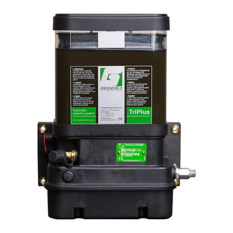
Groeneveld TriPlus Trailer Configuration guide

General Manual
Automatic Greasing System
TriPlus Trailer
F212157R02
Your efficiency is our Challenge!

All rights reserved. No part of this manual may be copied and/or published by means of printing, photocopying,
microfilm or by any other means without prior written permission from Groeneveld. This applies also to the
drawings and diagrams appended.
Groeneveld reserves the right to change parts at any time, without prior or direct notice to the customer. The
contents of this manual may also be changed without prior notice.
This manual applies to the standard version of the product. Groeneveld cannot accept liability for any damage
arising from the use of specifications other than that supplied.
You are requested to contact Groeneveld technical service for information concerning adjustment, maintenance
work or repairs that is not described in this manual.
Whilst this manual has been prepared with the greatest possible care Groeneveld cannot accept responsibility for
any errors of the concequences of such errors.
General information
Type of manual General Manual
System Automatic Greasing System TriPlus Trailer
Document number F212157R02
Date of issue September 2012
Revision 02

3Table of ContentsF212157R02
Automatic Greasing System TriPlus Trailer
Date of issue : September 2012
Table of Contents
Preface - - - - - - - - - - - - - - - - - - - - - - - - - - - - - - - - - - - - - - - - - - - - - - - - - - - - - - - 5
1. General information - - - - - - - - - - - - - - - - - - - - - - - - - - - - - - - - - - - - - - - - - - - - - 6
1.1. Introduction- - - - - - - - - - - - - - - - - - - - - - - - - - - - - - - - - - - - - - - - - - - - - - - - - - - - - - - - - 6
1.2. The TriPlus automatic greasing system - - - - - - - - - - - - - - - - - - - - - - - - - - - - - - - - - - - - - 7
2. Description components - - - - - - - - - - - - - - - - - - - - - - - - - - - - - - - - - - - - - - - - - - 8
2.1. Properties - - - - - - - - - - - - - - - - - - - - - - - - - - - - - - - - - - - - - - - - - - - - - - - - - - - - - - - - - - 8
2.2. Composition of the TriPlus trailer pump - - - - - - - - - - - - - - - - - - - - - - - - - - - - - - - - - - - - 9
2.3. The intigrated control and monitoring unit - - - - - - - - - - - - - - - - - - - - - - - - - - - - - - - - 10
2.4. The plunger pump - - - - - - - - - - - - - - - - - - - - - - - - - - - - - - - - - - - - - - - - - - - - - - - - - - - 10
2.5. Safety and control features - - - - - - - - - - - - - - - - - - - - - - - - - - - - - - - - - - - - - - - - - - - - 11
2.5.1. Maximum grease pressure - - - - - - - - - - - - - - - - - - - - - - - - - - - - - - - - - - - - - - 11
2.5.2. Minimum grease-level in the reservoir - - - - - - - - - - - - - - - - - - - - - - - - - - - - - 11
2.5.3. Defective wiring and short-circuits - - - - - - - - - - - - - - - - - - - - - - - - - - - - - - - - 11
2.6. The test pushbutton - - - - - - - - - - - - - - - - - - - - - - - - - - - - - - - - - - - - - - - - - - - - - - - - - - 12
2.6.1. Performing a test cycle - - - - - - - - - - - - - - - - - - - - - - - - - - - - - - - - - - - - - - - - - 12
2.6.2. Retrieving fault messages - - - - - - - - - - - - - - - - - - - - - - - - - - - - - - - - - - - - - - - 12
2.7. The signal light - - - - - - - - - - - - - - - - - - - - - - - - - - - - - - - - - - - - - - - - - - - - - - - - - - - - - 13
2.8. The distribution blocks - - - - - - - - - - - - - - - - - - - - - - - - - - - - - - - - - - - - - - - - - - - - - - - - 15
2.8.1. Properties- - - - - - - - - - - - - - - - - - - - - - - - - - - - - - - - - - - - - - - - - - - - - - - - - - - 15
2.8.2. Composition- - - - - - - - - - - - - - - - - - - - - - - - - - - - - - - - - - - - - - - - - - - - - - - - - 15
2.8.3. Principle of operation- - - - - - - - - - - - - - - - - - - - - - - - - - - - - - - - - - - - - - - - - - 16
2.8.4. Non-return valves - - - - - - - - - - - - - - - - - - - - - - - - - - - - - - - - - - - - - - - - - - - - - 17
2.8.5. Failure of one of the doser segments - - - - - - - - - - - - - - - - - - - - - - - - - - - - - - 17
2.8.6. Closing outputs - - - - - - - - - - - - - - - - - - - - - - - - - - - - - - - - - - - - - - - - - - - - - - 17
2.8.7. Combining outputs- - - - - - - - - - - - - - - - - - - - - - - - - - - - - - - - - - - - - - - - - - - - 17
3. The GINA - - - - - - - - - - - - - - - - - - - - - - - - - - - - - - - - - - - - - - - - - - - - - - - - - - - - 18
3.1. Introduction- - - - - - - - - - - - - - - - - - - - - - - - - - - - - - - - - - - - - - - - - - - - - - - - - - - - - - - - 18
3.2. Connecting the GINA - - - - - - - - - - - - - - - - - - - - - - - - - - - - - - - - - - - - - - - - - - - - - - - - - 19
3.3. Control pad - - - - - - - - - - - - - - - - - - - - - - - - - - - - - - - - - - - - - - - - - - - - - - - - - - - - - - - - 19
3.4. Switching on the GINA - - - - - - - - - - - - - - - - - - - - - - - - - - - - - - - - - - - - - - - - - - - - - - - - 19
3.5. Main menu - - - - - - - - - - - - - - - - - - - - - - - - - - - - - - - - - - - - - - - - - - - - - - - - - - - - - - - - 20
3.6. Parameters timer - - - - - - - - - - - - - - - - - - - - - - - - - - - - - - - - - - - - - - - - - - - - - - - - - - - - 23
3.7. Diagnosis menu - - - - - - - - - - - - - - - - - - - - - - - - - - - - - - - - - - - - - - - - - - - - - - - - - - - - - 25
3.8. Layout of the menu system- - - - - - - - - - - - - - - - - - - - - - - - - - - - - - - - - - - - - - - - - - - - - 31
3.8.1. Used abbreviations - - - - - - - - - - - - - - - - - - - - - - - - - - - - - - - - - - - - - - - - - - - - 31
3.8.2. Main menu- - - - - - - - - - - - - - - - - - - - - - - - - - - - - - - - - - - - - - - - - - - - - - - - - - 33
3.8.3. Parameters menu - - - - - - - - - - - - - - - - - - - - - - - - - - - - - - - - - - - - - - - - - - - - - 33
3.8.4. Diagnosis menu - - - - - - - - - - - - - - - - - - - - - - - - - - - - - - - - - - - - - - - - - - - - - - 34
4. Designing a system - - - - - - - - - - - - - - - - - - - - - - - - - - - - - - - - - - - - - - - - - - - - - 35
4.1. Introduction- - - - - - - - - - - - - - - - - - - - - - - - - - - - - - - - - - - - - - - - - - - - - - - - - - - - - - - - 35
4.2. Points of departure - - - - - - - - - - - - - - - - - - - - - - - - - - - - - - - - - - - - - - - - - - - - - - - - - - 35
4.3. Method - - - - - - - - - - - - - - - - - - - - - - - - - - - - - - - - - - - - - - - - - - - - - - - - - - - - - - - - - - - 37
4.3.1. Determine the operating conditions - - - - - - - - - - - - - - - - - - - - - - - - - - - - - - - 37
4.3.2. Produce a greasing plan - - - - - - - - - - - - - - - - - - - - - - - - - - - - - - - - - - - - - - - - 37
4.3.3. Determine the grease demand of the grease points - - - - - - - - - - - - - - - - - - - 37
4.3.4. Group the grease points - - - - - - - - - - - - - - - - - - - - - - - - - - - - - - - - - - - - - - - - 38
4.3.5. Determine the layout of the system - - - - - - - - - - - - - - - - - - - - - - - - - - - - - - - 38
4.3.6. Check the design - - - - - - - - - - - - - - - - - - - - - - - - - - - - - - - - - - - - - - - - - - - - - 39
Table of Contents4F212157R02
Automatic Greasing System TriPlus Trailer
Date of issue : September 2012
5. Installation - - - - - - - - - - - - - - - - - - - - - - - - - - - - - - - - - - - - - - - - - - - - - - - - - - - 40
5.1. Overview - - - - - - - - - - - - - - - - - - - - - - - - - - - - - - - - - - - - - - - - - - - - - - - - - - - - - - - - - - 40
5.2. Safety precautions - - - - - - - - - - - - - - - - - - - - - - - - - - - - - - - - - - - - - - - - - - - - - - - - - - - 40
5.3. General installation directives - - - - - - - - - - - - - - - - - - - - - - - - - - - - - - - - - - - - - - - - - - 41
5.4. TriPlus pump unit - - - - - - - - - - - - - - - - - - - - - - - - - - - - - - - - - - - - - - - - - - - - - - - - - - - - 42
5.4.1. Pump types - - - - - - - - - - - - - - - - - - - - - - - - - - - - - - - - - - - - - - - - - - - - - - - - - 42
5.4.2. Mounting the pump- - - - - - - - - - - - - - - - - - - - - - - - - - - - - - - - - - - - - - - - - - - 42
5.5. TriPlus distribution blocks- - - - - - - - - - - - - - - - - - - - - - - - - - - - - - - - - - - - - - - - - - - - - - 43
5.5.1. General - - - - - - - - - - - - - - - - - - - - - - - - - - - - - - - - - - - - - - - - - - - - - - - - - - - - 43
5.5.2. Assembling distribution blocks - - - - - - - - - - - - - - - - - - - - - - - - - - - - - - - - - - - 43
5.5.3. Mounting the distribution blocks - - - - - - - - - - - - - - - - - - - - - - - - - - - - - - - - - 44
5.6. Primary grease lines and couplings - - - - - - - - - - - - - - - - - - - - - - - - - - - - - - - - - - - - - - - 44
5.6.1. Grease line types - - - - - - - - - - - - - - - - - - - - - - - - - - - - - - - - - - - - - - - - - - - - - 44
5.6.2. Mounting the primary grease lines - - - - - - - - - - - - - - - - - - - - - - - - - - - - - - - - 44
5.7. Secondary grease lines and couplings - - - - - - - - - - - - - - - - - - - - - - - - - - - - - - - - - - - - - 46
5.7.1. Grease line types - - - - - - - - - - - - - - - - - - - - - - - - - - - - - - - - - - - - - - - - - - - - - 46
5.7.2. Mounting the secondary lines- - - - - - - - - - - - - - - - - - - - - - - - - - - - - - - - - - - - 47
5.8. Electrical wiring - - - - - - - - - - - - - - - - - - - - - - - - - - - - - - - - - - - - - - - - - - - - - - - - - - - - - 48
5.8.1. General - - - - - - - - - - - - - - - - - - - - - - - - - - - - - - - - - - - - - - - - - - - - - - - - - - - - 48
5.8.2. Fuse ratings - - - - - - - - - - - - - - - - - - - - - - - - - - - - - - - - - - - - - - - - - - - - - - - - - 48
5.8.3. Pin-layout of the connector on the pump unit - - - - - - - - - - - - - - - - - - - - - - - 48
5.8.4. Wiring diagram - - - - - - - - - - - - - - - - - - - - - - - - - - - - - - - - - - - - - - - - - - - - - - 49
5.9. De-aerating of the greasing system - - - - - - - - - - - - - - - - - - - - - - - - - - - - - - - - - - - - - - 50
5.10. Commissioning of the greasing system - - - - - - - - - - - - - - - - - - - - - - - - - - - - - - - - - - - - 50
6. Maintenance- - - - - - - - - - - - - - - - - - - - - - - - - - - - - - - - - - - - - - - - - - - - - - - - - - 51
6.1. General - - - - - - - - - - - - - - - - - - - - - - - - - - - - - - - - - - - - - - - - - - - - - - - - - - - - - - - - - - - 51
6.2. Regularly checks of the greasing system - - - - - - - - - - - - - - - - - - - - - - - - - - - - - - - - - - - 51
6.3. Filling the grease reservoir - - - - - - - - - - - - - - - - - - - - - - - - - - - - - - - - - - - - - - - - - - - - - 52
6.4. Fault finding - - - - - - - - - - - - - - - - - - - - - - - - - - - - - - - - - - - - - - - - - - - - - - - - - - - - - - - 53
7. Technical data- - - - - - - - - - - - - - - - - - - - - - - - - - - - - - - - - - - - - - - - - - - - - - - - - 55
7.1. TriPlus trailer pump unit- - - - - - - - - - - - - - - - - - - - - - - - - - - - - - - - - - - - - - - - - - - - - - - 55
7.2. Distribution blocks - - - - - - - - - - - - - - - - - - - - - - - - - - - - - - - - - - - - - - - - - - - - - - - - - - - 56

Automatic Greasing System TriPlus Trailer
Preface 5
Date of issue : September 2012
F212157R02
Preface
This general manual gives a description of the TriPlus automatic greasing system. It aims at giving
insight in the system’s operation and possibilities. Furthermore, in this manual you will find the
technical data on several components of the TriPlus automatic greasing system.
In this manual the following icons are used to inform or warn the user:
ATTENTION
Draws the user’s attention to important information meant to avoid problems.
WARNING
Warns the user for physical injuries or serious damage to the equipment caused by improper
actions.

General information6
Date of issue : September 2012
Automatic Greasing System TriPlus Trailer
F212157R02
1. General information
1.1 Introduction
With an automatic greasing system of
Groeneveld
all grease points of a vehicle or machine are
lubricated automatically at the correct moment and with the correct amount of grease. Because
greasing takes places while the vehicle or machine is in operation, the applied grease is spread
optimally over the whole surface to be greased. The greasing system requires no user intervention
to operate, apart from periodically replacing the grease in its reservoir.
Groeneveld’s
automatic greasing systems are designed with the utmost care and tested rigorously.
This guarantees an extended operational life and error-free operation, even under the most
extreme operating conditions.
Proper installation, using the correct type of grease, and periodic checks are prerequisites for the
continual hassle-free operation of the system. The periodic checks, which take little time and effort,
can be performed during the normal maintenance of the vehicle or machine (during oil-
replacement, for instance). Careful selection of construction materials, makes the greasing system
itself vitually maintenance-free.
ATTENTION
The automatic greasing system reduces the time and effort spent on manual greasing significantly.
However, do not forget that there may be grease points that are not served by the greasing system
and must still be greased by hand.

Automatic Greasing System TriPlus Trailer
General information 7
Date of issue : September 2012
F212157R02
1.2 The TriPlus automatic greasing system
A
Groeneveld
TriPlus automatic greasing system serves each grease point of the vehicle, machine
or installation in sequence, i.e. grease is supplied to the connected grease points one at a time and
one after the other (it is a progressive greasing system).
TriPlus systems are mainly applied on machines with a fixed number of grease points that require
fixed amounts of grease at fixed intervals. This, because the amount of grease that will be supplied
to the individual grease points is governed by the distribution ratios that results from the choice of
doser segment types and the manner in which those segments are combined in distribution blocks.
A
Groeneveld
TriPlus automatic greasing system comprises the following parts (see Figure 1.1):
1. An electric grease pump (plunger pump) with integrated grease reservoir and a digital
control unit with data storage facility.
2. One or more distribution blocks (assembled from multiple doser segments).
3. Primary grease lines between the pump unit and the distribution blocks and interconnecting
the distribution blocks themselves.
4. Secondary grease lines between the distribution blocks (doser segments) and the individual
grease points.
Figure 1.1 System overview
Two types of pump units are available:
• The TriPlus pump
• The TriPlus trailer-pump
The TriPlus pump is applied when the supply voltage needed to power the greasing system is always
available (while the vehicle or machine is in operation). The TriPlus trailer-pump is used on pulled
vehicles, where the supply voltage will not (always) be available.

Description components8
Date of issue : September 2012
Automatic Greasing System TriPlus Trailer
F212157R02
2. Description components
2.1 Properties
The
Groeneveld
TriPlus trailer pump is designed specifically for use on machines and pulled
vehicles on which a supply voltage for the greasing system is not (always) available while the vehicle
(trailers) or machine is in operation. The trailer pump unit features an integrated control unit.
The most significant properties of the TriPlus trailer pump unit are:
• The grease interval is determined by the number of brake commands received by the braking
system;
• The grease output of the pump is monitored;
• The maximum acceptable grease pressure is monitored;
• The grease level in the reservoir is monitored;
• The electrical wiring and components are monitored.

Automatic Greasing System TriPlus Trailer
Description components 9
Date of issue : September 2012
F212157R02
2.2 Composition of the TriPlus trailer pump
The TriPlus trailer pump comprised the following components:
1. Grease reservoir with follower piston.
2. Stirring gear.
3. Plunger pump.
4. Electronic control and monitoring unit with permanent memory.
5. Relief valve with return line to the grease reservoir and electric contact for monitoring
purposes by the control unit.
6. Grease output port 1.
7. Impulse sender used to count the number of revolutions of the drive shaft of the pump.
8. Electric motor with reduction gear.
9. Test pushbutton.
10. Filler grease nipple with filter.
11. De-aerating and grease-overflow opening.
12. Electrical connector.
13. Minimum grease-level switch.
Figure 2.1 TriPlus trailer pump

Description components10
Date of issue : September 2012
Automatic Greasing System TriPlus Trailer
F212157R02
2.3 The intigrated control and monitoring unit
The control and monitoring unit iniates and controls the greasing cycles of the greasing system. All
required system and program parameters, such as at which intervals (number of brake commands
or pulses) grease should be applied and with what quanties, are laid down in the control unit. The
control unit monitors the performance of various components of the greasing system, and stores
and reports the malfunction it detects.
The control unit can be programmed or read-out with a GINA (Groeneveld tester for INstallation
and Analysis) (see Figure 2.2)
Figure 2.2 Connecting the GINA to the trailer pump
2.4 The plunger pump
The electric motor drives the plunger pump through a reduction gear. The plunger pump comprises
a drive shaft with excentric, a cylinder with piston, and a non-return valve. The excentric moves the
piston back and forth, once every revolution of the drive shaft. During the return stroke of the
piston, grease is sucked from the reservoir into the cylinder (through an opening in the cylinder
wall). During the forward stroke of the piston, the grease is pressed, via the non-return valve,
towards the output port(s) of the pump unit. The amount of grease supplied during each stroke
(revolutions of the drive shaft) depends on the (fixed) diameter of the cylinder and the stroke
length of the piston.

Automatic Greasing System TriPlus Trailer
Description components 11
Date of issue : September 2012
F212157R02
2.5 Safety and control features
2.5.1 Maximum grease pressure
A relief valve (fitted with an electrical contact) is installed in the grease channel between the
plunger pump and the output port. This relief valve will start to lead the grease back to the
reservoir if the maximum grease pressure is exceeded during the pump phase of a greasing cycle.
The grease pressure may become too high, for example, when one of the grease lines to the grease
points has become blocked, or when the viscosity of the grease has become too high (at low
temperature).
2.5.2 Minimum grease-level in the reservoir
A minimum-level switch is installed in the grease reservoir. If the grease reaches its minimum level,
the control unit will process, store and report the occurrence of that condition.
2.5.3 Defective wiring and short-circuits
Open-loads (interruptions) in the wiring to the sensors, minimum-level switch, relief valve, electric
motor and external signalling devices (e.g. buzzer or signal light) will be detected and processed by
the control unit. Short-circuits in the wiring or components will also be noticed by the control unit.

Description components12
Date of issue : September 2012
Automatic Greasing System TriPlus Trailer
F212157R02
2.6 The test pushbutton
The test pushbutton on the pump unit has two functions:
• Performing a test cycle via one of the grease output ports of the pump unit.
• Retrieving error messages stored in the memory of the control unit.
Figure 2.3 The test pushbutton
2.6.1 Performing a test cycle
A test cycle can be performed using the test pushbutton, as follow:
1. The supply voltage for the pump unit must be available (brakes on).
2. Press the test pushbutton momentarily (not longer than 1 second), one time.
3. The test cycle starts two seconds after you pressed the test pushbutton.
During the test cycle the signal light will blink at a particular frequency.
Any errors that occur during the test cycle will not be indicated by the signal light and will not be
stored in the memory of the control unit.
2.6.2 Retrieving fault messages
In the memory of the control unit information is stored about the operation of the greasing system.
Two categories of fault messages can be distinguished:
1. Pending errors: errors that were detected since the control unit was switched on last (from
the moment the supply voltage became available).
2. Stored errors: all errors that were detected by the control unit in the past.
All new errors that occur will be stored as pending errors. If the control unit is switched off all
pending errors will be added to list of stored errors, and the list with the pending errors will be
erased.
Retrieving fault messages:
The fault messages stored in the control unit’s memory can be retrieved by keeping the test
pushbutton on the pump unit depressed for at least five seconds. Seven seconds after you released
the test pushbutton the signal light will start producing the blink codes to indicate the stored
errors.

Automatic Greasing System TriPlus Trailer
Description components 13
Date of issue : September 2012
F212157R02
2.7 The signal light
The driver or operator will be informed about the operation of the
greasing system through a signal light which is installed on the
dashboard in the cabin. The physical form of the signal light may vary,
but it is always installed so that is easily visible.
Figure 2.4 The signal light
The signal light produces the following signals:
Signal Moment Significance
1 x 3 seconds on. 5 seconds after switching on
contact.
The supply voltage for the
control unit is available and
the signal light is OK.
1 x 2 minutes on. After completion of a pump
phase.
An error occurred during the
pump phase. Precisely which
error occur-red can be deter-
mined by using the test push-
button.
Repeatedly: 1 x 0,3 seconds
on, followed by a pause of 2
seconds.
After momentarily pressing
the test pushbutton once.
A test cycle is being per-
formed via grease output
port 1.
GROENEVELD
976.01

Description components14
Date of issue : September 2012
Automatic Greasing System TriPlus Trailer
F212157R02
The signal light indicates the fault codes by blinking:
The decades of the fault code: long pulses (0,5 seconds)
The units of the fault code: short pulses (0,15 seconds)
There is a two second pause between successive fault codes. For example, if the fault codes 13 and
22 are displayed, you will see the blink codes:
long, short, short, short
fault code 13
two second pause
long, long, short, short
fault code 22
two second pause
Each fault message has been assigned a two-digit fault code:
Fault code Meaning
10 No error on this moment.
11 Distribution block monitoring switch has not switched.
12 Relief valve activated during a pumpphase in output port 1
(maximum grease pressure exceeded).
15 Grease reservoir is empty.
21 The pump did not complete the programmed number of revolutions within the set
time.
22 Pump motor: open load.
23 Pump motor eliminated during pump phase concerning a too high flow usage.
33 Signal light: open load.
34 Signal light: short circuit in wiring (or lampfitting).
35 Short circuit components or wiring called in of above.

Automatic Greasing System TriPlus Trailer
Description components 15
Date of issue : September 2012
F212157R02
2.8 The distribution blocks
2.8.1 Properties
TriPlus distribution blocks distribute the grease to the various grease points and meter-out the
amount of grease that goes to each individual grease point. They do so in a progressive, sequential
way. The progressive distribution blocks in the greasing system distribute the grease to the grease
points, one grease point at a time, and one grease point after another. Progressive distribution
blocks can be placed in series, in which case an output of a block is used to feed the next block in
line (through a primary grease line).
2.8.2 Composition
A progressive distribution block comprises the
following components:
1. a start-segment
2. an end-segment
3. at least three doser segments
The doser segments to be deliverable in several
versions with several amounts (quantity of grease
which by cycle it is supplied). By several doser
segments in a distribution block combine can a certain
partitioning of the grease be obtained.
Figure 2.5 Distribution block
Each doser segment always has two grease output ports, with identical grease outputs per cycle.
The grease channels between the segments are sealed by O-rings and the segments are pressed
together with two compression bolts.

Description components16
Date of issue : September 2012
Automatic Greasing System TriPlus Trailer
F212157R02
2.8.3 Principle of operation
Figure 2.6 Principle of operation
To operate, progressive distribution blocks need no other energy source than the grease pressure
supplied by the pump of the greasing system:
1. The lubricant flows from the input port, via piston 3, through all segments to the left-hand
side of piston 1.
2. Piston 1 is pushed to the right by the grease pressure. The grease at the right-hand side of
piston 1 is pressed to output port 1.
Because piston 1 has now been pushed to the right, the lubricant now flows, via piston 1,
from the central input channel to the left-hand side of piston 2.
3. Piston 2 is then moves and supplies grease to output 2.
Because piston 2 has been pushed to the right, the lubricant now flows, via piston 2, to the
left-hand side of piston 3. Piston 3 is pushed to the right and supplies lubricant to output port
3.
4. After piston 3 has been pushed to the right, the lubricant is pressed to the right-hand side of
piston 1. Piston 1 will move to the left and supply lubricant to output port 4.
5. Afterwards piston 2 will also be pressed to the right and will supply lubricant to output port
5.
6. Afterwards piston 3 will also be pressed to the right and will supply lubricant to output port
6.
7. The distribution block then arrives back at its starting-off point, and the cycle will repeat as
long as there is pressure in the primary grease line.
REMARK
The description and illustration above assume there is a fixed starting-off point for the doser
segments in the distribution block. This is not so. The distribution block always continues from
where it left-off during the previous pump phase of the grease cycle.
WARNING
To be able to operate at all, a distribution block needs to have at least three doser segments.

Automatic Greasing System TriPlus Trailer
Description components 17
Date of issue : September 2012
F212157R02
2.8.4 Non-return valves
Non-return valves are installed in the outputs of the distribution block to prevent lubricant from
flowing back into the distribution block. All output ports to which primary lines are connected or
which are used to interconnect distribution blocks must be fitted with non-return valves. Output
ports which secondary grease lines are connected, must be fitted with non-return valves if
significantly different return pressures are expected at different output ports.
2.8.5 Failure of one of the doser segments
If one of the doser segments fails to operate properly (due to internal or external damage), the
whole greasing system will fail to operate.
2.8.6 Closing outputs
An output may only be closed-off after removal of the little plug that seperates the two outputs of
a doser segment. Removing the plug allows the grease meant for the close-off to exit through the
output that remains open (it doubles the output of the one that remains open). The distribution
block will become inoperable if the little plug is not removed.
2.8.7 Combining outputs
The outputs of a distribution block can be combined by installing an external interconnection line.
The total grease output in that case is the sum of all outputs thus interconnected.
The two outputs of a doser segment can be combined by removing the little internal plug that
seperates the two outputs and closing-off one of the ports. This doubles the output of the port that
remains open.
Figure 2.7 Combining outputs
The values in the illustration represent the outputs of the ports in mm³ (0,001 cc) per complete cycle
of the distribution block. The amount supplied is determined by the diameter of the piston.
1
1
3
3
4

The GINA18
Date of issue : September 2012
Automatic Greasing System TriPlus Trailer
F212157R02
3. The GINA
3.1 Introduction
The GINA (Groeneveld tester for Installation and Analysis) is a programming and read-out device
for the digital control unit of the TriPlus automatic greasing system.
Figure 3.1 The GINA
In the description that follows all screens of the GINA are dealt with in the order in which they have
been placed in its menu system. To get acquainted with the menu system and the features the GINA
offers, we advise you to follow the sequence as presented, if only once. In practise there is, of
course, no reason whatsever for such a rigid and time consuming approach.
The read-outs and setting have been grouped in three menus: main menu, para-meters timer and
diagnosis menu. You can access each of these menus by pressing <MAIN>, <PARAMETERS> or
<DIAGNOSIS> on the keypad of the GINA.
You can do so at any time, regardless of the screen currently shown on the display.
Some screens just show information. You cannot change anything in those screens. Other screens
allow you to change parameters or the status of a particular input or output. You can recognise
those screens by the blinking cursor that appears on them (with the exception of the system
configuration and error-logging-reset screens).
A number of screens show the current time in their top-right corner. In the screens, as reproduced
in this manual, this is indicated by hh:mm:ss.
Values are usually denoted to by a number of x-signs, with one ‘x’for every possible digit in the
number.

Automatic Greasing System TriPlus Trailer
The GINA 19
Date of issue : September 2012
F212157R02
3.2 Connecting the GINA
The supply voltage of the control unit to be read or programmed must be available (from the
vehicle or an external power supply, if need be).
Connect the GINA with the control unit, using the supplied interconnection cable.
3.3 Control pad
3.4 Switching on the GINA
The GINA can be switched-on after:
• the GINA has been connected with the control unit, and
• the power supply has been available to the control unit for at least 8 seconds.
Press <POWER ON/OFF>.
You can access the main menu, parameters timer and diagnosis menu by pressing, respectively
<MAIN>, <PARAMETERS> or <DIAGNOSIS>.
This message appears when the GINA is unable to communicate with the control unit:
This can be cause by:
• bad connection (wire in cable broken or bad connector).
• GINA switched-on too quickly.
Always try to alleviate the problem first by turning the GINA off and then on again, or by pressing
one of the softkeys (<F1>, <F2>, <F3> or <F4>).
Key Function
<POWER ON/OFF> to turn the GINA on or off (toggle)
<F1> .. <F4> ('soft keys') to make a particular choice in a menu
<0> .. <9> to enter numerical data
<MAIN> to call the main menu to view miscellaneous information
<PARAMETERS> to call the parameter menu to view and enter parameter data
<DIAGNOSIS> to call the diagnosis menu to view various system data
<NEXT> to go to the next screen in the menu system
<ENTER> to confirm a setting you have changed or entered
Communication error

The GINA20
Date of issue : September 2012
Automatic Greasing System TriPlus Trailer
F212157R02
This message appears if the control unit is not supported by this GINA:
You need another GINA to access this control unit.
3.5 Main menu
Press <main>
The main menu contains various data about the GINA and
the control unit that is connected. You can change only
some of the data.
Press <F1> (info).
The screen shows the indification number of the person
who most recently connected a GINA to this control unit.
ATTENTION: This number is overwritten when the GINA is
switched off, with your own indification number.
Press <F2> (d-ac).
The screen shows the date and time at which a GINA has,
most recently, been connected with this control unit.
ATTENTION: This date and time will be updated when you
switched-off the GINA.
Press <F3> (u-ch).
The screen shows the identification number of the person
who, most recently, changed any settings of this control
unit.
ATTENTION: This number will be over-written with your
own identification number when you switch-off the GINA,
provided you have changed at least one setting.
Press <F4> (d-ch).
The screen shows the date and time at which the settings of
this control unit were most recently changed.
ATTENTION: This time and date will be updated when you
switch-off the GINA, provided you have changed at least
one setting.
Press <NEXT>.
DEVICE NOT SUPPORTED
MAIN MENU
info time contr
INFO
User ID
last access: xxxxxx
u-ac d-ac u-ch d-ch
INFO
Time&date , last access
xx-xx-xx xx:xx
u-ac d-ac u-ch d-ch
INFO
User ID
last change: xxxxxx
u-ac d-ac u-ch d-ch
INFO
Time&date , last change
xx-xx-xx xx:xx
u-ac d-ac u-ch d-ch
Table of contents
Other Groeneveld Lubrication System manuals

Groeneveld
Groeneveld CompAlube Configuration guide

Groeneveld
Groeneveld MultiLine SFi Manual

Groeneveld
Groeneveld TWIN Configuration guide

Groeneveld
Groeneveld Multiline AC Series User manual

Groeneveld
Groeneveld EcoPlus Installation instructions

Groeneveld
Groeneveld OnePlus Configuration guide

Groeneveld
Groeneveld MultiLine SFi 110 User manual

Groeneveld
Groeneveld Multiline AC F219157R03 User manual

Groeneveld
Groeneveld BreakAlube-3 Configuration guide

Groeneveld
Groeneveld Twin-3 Configuration guide