English (GB)
2
English (GB) Functional profile and user manual
Original functional profile and user manual.
CONTENTS
Page
1. Symbols used in this document
2. Introduction
2.1 About this functional profile
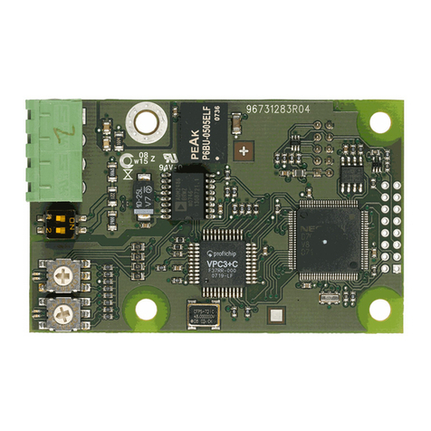
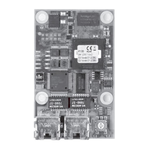
This functional profile describes the CIM 110 and CIU 110 for
LON communication with the following Grundfos booster
systems:
• Grundfos Hydro Multi-B (CU 323)
Hydro Multi-B is a complete booster system incorporating
Grundfos CM/CME pumps.
• Grundfos Hydro MPC (CU 352)
Hydro MPC is a complete booster system incorporating
Grundfos CRE pumps.
• Grundfos Control MPC (CU 352)
Control MPC can be built with different pump types to form a
booster system.
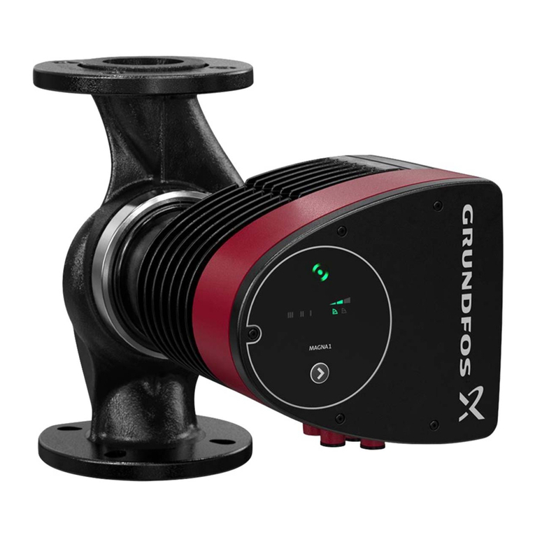
• Grundfos Multi-E
A booster set based on Grundfos MGE pumps model H and
later.
• Grundfos TPED twin-head pump with MGE motor, model H/I,
in multipump-mode (CIM 110 must be in the master pump
head).
• MAGNA3 Twinpump in multipump mode
Requires a CIM110 module installed in the master pump.
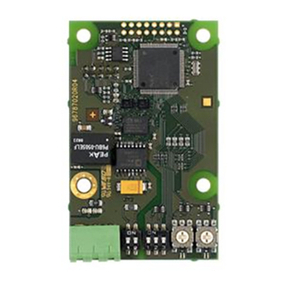
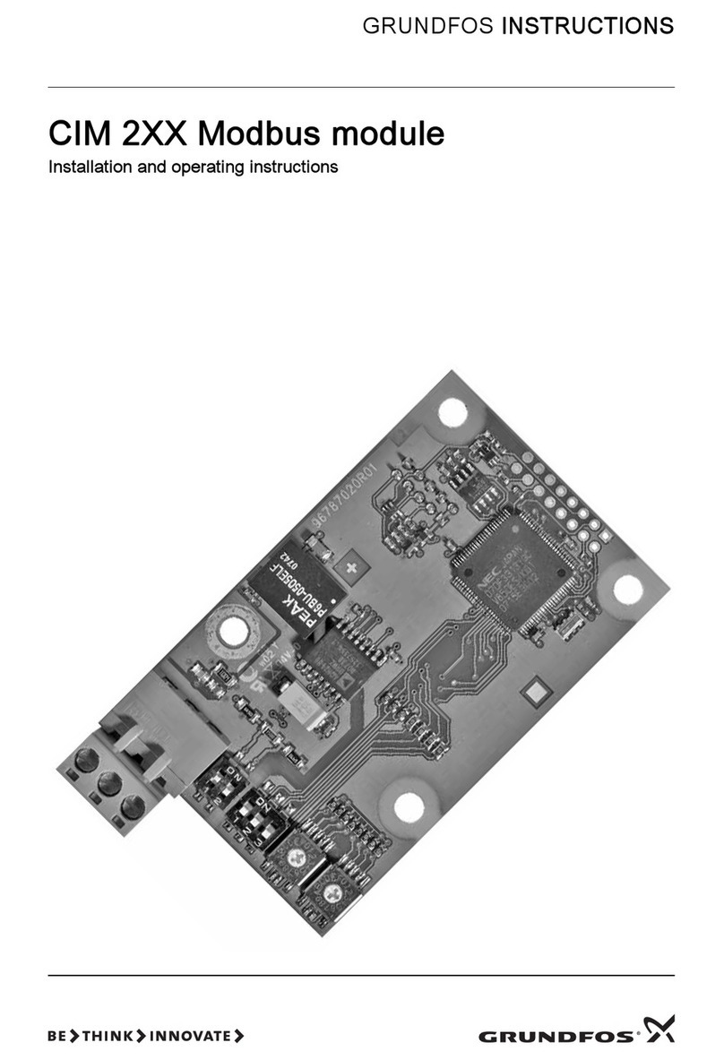
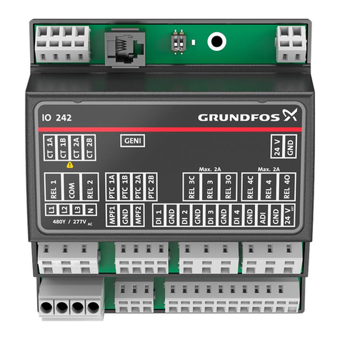
The CIU 110 incorporates a CIM 110 (LON Communication
Interface Module 110).
References in the following:
• The CIM 110 module is referred to as "LON module".
• The Hydro Multi-B, Hydro MPC, Multi-E and Control MPC are
referred to as "controller".
Control MPC and Hydro MPC are referred to as "Hydro MPC".
The data in this document are subject to change without prior
notice. Grundfos cannot be held responsible for any problems
caused directly or indirectly by using information in this functional
profile.
2.2 Assumptions
This functional profile assumes that the reader is familiar with
commissioning and programming LON devices. The reader
should also have some basic knowledge of the anatomy of LON
data communication.
1. Symbols used in this document 2
2. Introduction 2
2.1 About this functional profile 2
2.2 Assumptions 2
2.3 Definitions and abbreviations 3
2.4 System diagram 3
3. Installation 3
4. CIM 110 LON module 4
4.1 Connecting the LON module 4
4.2 Registration in a LON network 5
4.3 LEDs 5
5. Considerations when installing the controller 5
6. Selection of primary sensor 6
7. Power-on behaviour 6
8. SNVT/UNVT details 7
8.1 Mandatory and optional network variables 7
8.2 Manufacturer-defined network variables 7
8.3 Optional subpump (UFPT) network variables 7
9. SCPT/UCPT details 8
9.1 Configuration properties 8
10. Application examples 9
11. Override functionality 10
12. Details of the pump controller's functional blocks 11
12.1 Pump setpoint 13
12.2 Requested pump operating mode 13
12.3 Pump capacity 13
12.4 Effective operating mode 14
12.5 Effective device control mode 15
12.6 Pump status, diagnostic information 16
12.7 Pump differential pressure (standard range) 16
12.8 Pump differential pressure (extended range) 16
12.9 Pump inlet pressure 16
12.10 Pump discharge pressure (standard range) 16
12.11 Pump discharge pressure (extended range) 17
12.12 Pump external pressure (standard range) 17
12.13 Pump external pressure (extended range) 17
12.14 Pump flow (standard range) 17
12.15 Pump flow (extended range) 17
12.16 Flow-pipe liquid temperature 17
12.17 Return-pipe liquid temperature 17
12.18 Differential liquid temperature 18
12.19 Surrounding temperature 18
12.20 Tank level 18
12.21 Runtime 18
12.22 System status 18
12.23 Pump fault status 18
12.24 Alarm code 21
12.25 Warning code 21
12.26 Power consumption in kilowatts 21
12.27 Energy consumption 21
12.28 Send heartbeat 21
12.29 Control mode for normal operation 21
13. Details of the subpump's functional block 22
13.1 Pump speed 22
13.2 Pump runtime 22
13.3 Pump fault status 22
13.4 Pump status, diagnostic information 24
14. Details of the node object's functional block 25
14.1 Object request 25
14.2 Object status 25
14.3 Location label 25
15. Manufacturer-specific variables 26
15.1 Grundfos info 26
15.2 Device resource files 26
16. Sensor ranges 27
16.1 Positive sensor ranges 27
16.2 Negative sensor ranges 27
17. Fault finding 28
If these safety instructions are not observed, it may
result in malfunction or damage to the equipment.
Notes or instructions that make the job easier and
ensure safe operation.
