PHP A-4, 6, 8 & 9 Instruction Manual / General
1 General
1.1 Tender text
PHP for lossless storage of the expansion volume and for
pressure maintenance in closed heating, climate and cooling
systems. Designed and manufactured acc. to regulations of
EN 12828 and SWKI 93-1.
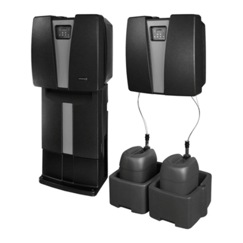
The PHP device is a nicely shaped, self-contained unit
with a pleasing design. It is designed for a modular
combination with external expansion vessels (max. 0.5 bar).
The connections for suction pipe and overflow pipe are
situated at the back of the device.
The control unit is built very compact with one resp.
two low-noise pressure maintenance pump(s) which are
executed as multistage centrifugal pump(s) with high
quality floating-ring type shaft seal. Also the PHP hydraulics
includes one resp. two continuously regulating, mechanically
set overflow valve of the expansion flow. High-precision
measuring of the plant pressure. Hydraulic connections and
necessary shut off devices for on-site piping are factory
provided on the left side of the control unit (possibility for
rebuilding to the right side of the control unit). Temperature
monitoring of the media streaming into the vessel.
Prepared connection point for mounting a makeup module
for a per litre accurate measuring. Combinable with an
option for water softening for standardized makeup water.
Prepared connection point for mounting a degassing module
for automatic and economic low pressure degassing, based
on the principle of pressure drop. The connection and the
necessary shut off device for the degassing pipe is situated
at the back of the control unit.
All operations are controlled by the microprocessor electronics.
The operator panel is situated ergonomically and contains an
illuminated 4-line text display. The handling is thought-out and
a lot of languages are supported. The measure and control
unit is executed in a closed electrical cabinet. Four potential-
free signalling contacts (fault, warning, makeup in operation,
device operation enabled).
For more signals two additional expansion modules
can be installed easily in prepared mounting positions.
Remote monitoring can be done also via PHP SMS module
or PHP bus module. External temperature monitoring
via an optional temperature sensor at the connection point
is prepared too.
Max. operation temperature of the plant: 110 °C
(with cooling vessel)
Max. temperature at the connection point: 70 °C
03
