manuals.online logo
Brands
  1. Home
  2. •
  3. Brands
  4. •
  5. REXROTH
  6. •
  7. Industrial Equipment
  8. •
  9. REXROTH TS2 plus User manual

REXROTH TS2 plus User manual

4.1
Hydraulics
Electric Drives
and Controls Linear Motion and
Assembly Technologies Pneumatics Service
The Drive & Control Company
Transfersystem TS 2plus
Transfer system TS 2plus
Système de transfert TS 2plus
Ausgabe
Version
Version
Bosch Rexroth AG TS 2plus 4.10–2
Clean
Room
100 N
240 mm
4...6 bar
1200mm
4 mm
60 kg
kg/cm
kg/cm
kg/cm
Vplus
3 842 531 138 (2011.04)
Symbole
Symbols
Symbols
Zulässige Belastung, Einzellast
Permissible load, single load
Charge maximale autorisée, charge unique
Geeignet für Einsatz in elektrostatisch
gefährdeten Bereichen. Die Rücksprache mit
Ihrer Rexroth-Fachvertretung wird empfohlen.
Suitable for use in ESD sensitive areas.
A contact with your Rexroth representative is
recommended.
Indiqué pour l’utilisation en zones sensibles aux
décharges électrostatiques. Nous conseillons
contacter votre représentant Rexroth.
Fördermittel
Conveying media
Convoyeurs
Produkteigenschaften
Product features
Charactéristiques du produit
Geeignet für den Einsatz in Reinräumen
Suitable for use in clean rooms
Indiqué pour l’utilisation en zones propres
Einsatztemperatur
Operating temperature
Température d‘utilisation
Wiederholgenauigkeit
Reproducing accuracy
Précision de répétition
Zulässige Prozesskraft
Permissible process force
Force de traitement maximale autorisée
Druckluftanschluß erforderlich
Pneumatic connection required
Raccordement pneumatique nécessaire
Einheit verfügt über eigenen Antrieb
Unit has an own drive
Module avec moteur traction
Hub über Transportniveau
Lift above transpotation level
Hauteur de levée sur niveau de transport
Reversierbetrieb bis 1200 mm zulässig
Reverse operation permissible up to 1200 mm
Fonctionnement inverse autorisée jusqu’à 1200 mm
Zulässige Belastung, Summenlast
Permissible load, sum of loads
Charge maximale autorisée, total des charges
Druckluft-Klemmanschluss "Steckfix"
Pneumatic connection "Steckfix"
Raccordement pneumatique "Steckfix" Klassifikation LC (Light Class)
LC (Light Class) classification
Classification LC (Light Class)
Klassifikation MR (Mid Range)
MR (Mid Range) classification
Classification MR (Mid Range)
Transportebene
Transport level
Niveau de Transport Klassifikation HD (Heavy Duty)
HD (Heavy Duty) classification
Classification HD (Heavy Duty)
Verweis auf weiterführende Informationen
Reference to additional information
Renvoi à des informations supplémentaires
Verweis auf technische Daten / Maße
Reference to technical data/dimensions
Renvoi à des données techniques/dimensions
Klassifikation
Classification
Classification
Verweise
References
Renvois
Zahnriemen
Toothed belt
Courroie dentée
Gurt
Belt
Courroie
Rollen
Rollers
Rouleaux
Flachplattenkette
Flat top chain
Chaîne à plate-formes
Staurollenkette
Accumulation roller chain
Chaîne à rouleaux d’accumulation
Rundriemen
Rounded belt
Courroie ronde
Staurollenkette Vplus
Vplus Accumulation roller chain
Chaîne à rouleaux d’accumulation Vplus
Bosch Rexroth AGTS 2plus 4.1 0–3
00013240.eps
00013241.eps
00012919.eps
00012896.eps
 2-5  2-6  2-8  2-18
00013181.eps
00013208.eps
00012914.eps
 3-6  3-12  3-14  3-16
 3-26  3-34  3-38  3-40
 3-54  3-60  3-64  3-66
00125186.eps
00012741.eps
00012745.eps
00012748.eps
 4-4  4-6  4-16  4-22
00116138.eps
00116135.eps
00117829.eps
 5-4  5-14  5-34  5-38
00108434.eps
00116809.eps
00116807.eps
00116805.eps
 6-4  6-6  6-7
00108286.eps
 7-4  7-12  7-16  7-24
001
08295.eps
00116596.eps
00116592.eps
00117846.eps
00116737.eps
00116755.eps
00116594.eps
00116760.eps
 8-4  8-19  8-23  8-31
3 842 531 138 (2011.04)
Systemübersicht TS 2plus
System overview of TS 2plus
Vue d’ensemble du système TS 2plus
Bosch Rexroth AG TS 2plus 4.10–4 3 842 531 138 (2011.04)
1
2
3
4
5
6
7
8
9
10
11
12
13
14
15
16
17
1
2
3
4
5
6
7
8
9
10
11
12
13
14
15
16
17
Bosch Rexroth AGTS 2plus 4.1 1–1
Eigenschaften TS 2plus · TS 2plus features · Caractéristiques TS 2plus
3 842 531 138 (2011.04)
Eigenschaften TS 2plus
Werkstückträger
Längstransport
Quertransport
Workpiece pallets
Longitudinal conveyors
Leg sets
Positioning and Orientation
TS 2plus features
Transverse conveyors
Positionieren und Orientieren
Transportsteuerung
Identifikationssysteme
Projektierung
Technische Daten
Bestellnummern-Übersicht
Index
Transportation control
Identification systems
Planning
Technical data
Overview of part numbers
Caractéristiques TS 2plus
Palettes porte-pièces
Transport longitudinal
Supports
Positionnement et Orientation
Commande de transport
Systèmes d’identification
Projeter
Données techniques
Sommaire des références
Transport transversal
Stützen
Kurven
Curves
Courbes
Index
Index
Inhaltsverzeichnis
Table of Contents
Sommaire
Die angegebenen Daten dienen allein der Produktbeschreibung. Eine
Aussage über eine bestimmte Beschaffenheit oder eine Eignung für einen
bestimmten Einsatzzweck kann aus unseren Angaben nicht abgeleitet
werden. Die Angaben entbinden den Verwender nicht von eigenen
Beurteilungen und Prüfungen. Es ist zu beachten, dass unsere Produkte
einem natürlichen Verschleiß- und Alterungsprozess unterliegen.
The data specified above only serve to describe the product. No
statements concerning a certain condition or suitability for a certain
application can be derived from our information. The information given
does not release the user from the obligation of own judgment and
verification. It must be remembered that our products are subject to a
natural process of wear and aging.
Les indications données servent exclusivement à la description du
produit. Il ne peut être déduit de nos indications aucune déclaration
quant aux propriétés précises ou à l’adéquation du produit en vue d’une
application précise. Ces indications ne dispensent pas l’utilisateur d’une
appréciation et d’une vérification personnelle. Il convient de tenir compte
du fait que nos produits sont soumis à un processus naturel d’usure et
de vieillissement.
Bosch Rexroth AG TS 2plus 4.11–2
Eigenschaften TS 2plus · TS 2plus features · Caractéristiques TS 2plus
3 842 531 138 (2011.04)
Funktionsprinzip
Operating principle
Principe de fonctionnement
Hauptschluss
Main circuit
Circuit principal

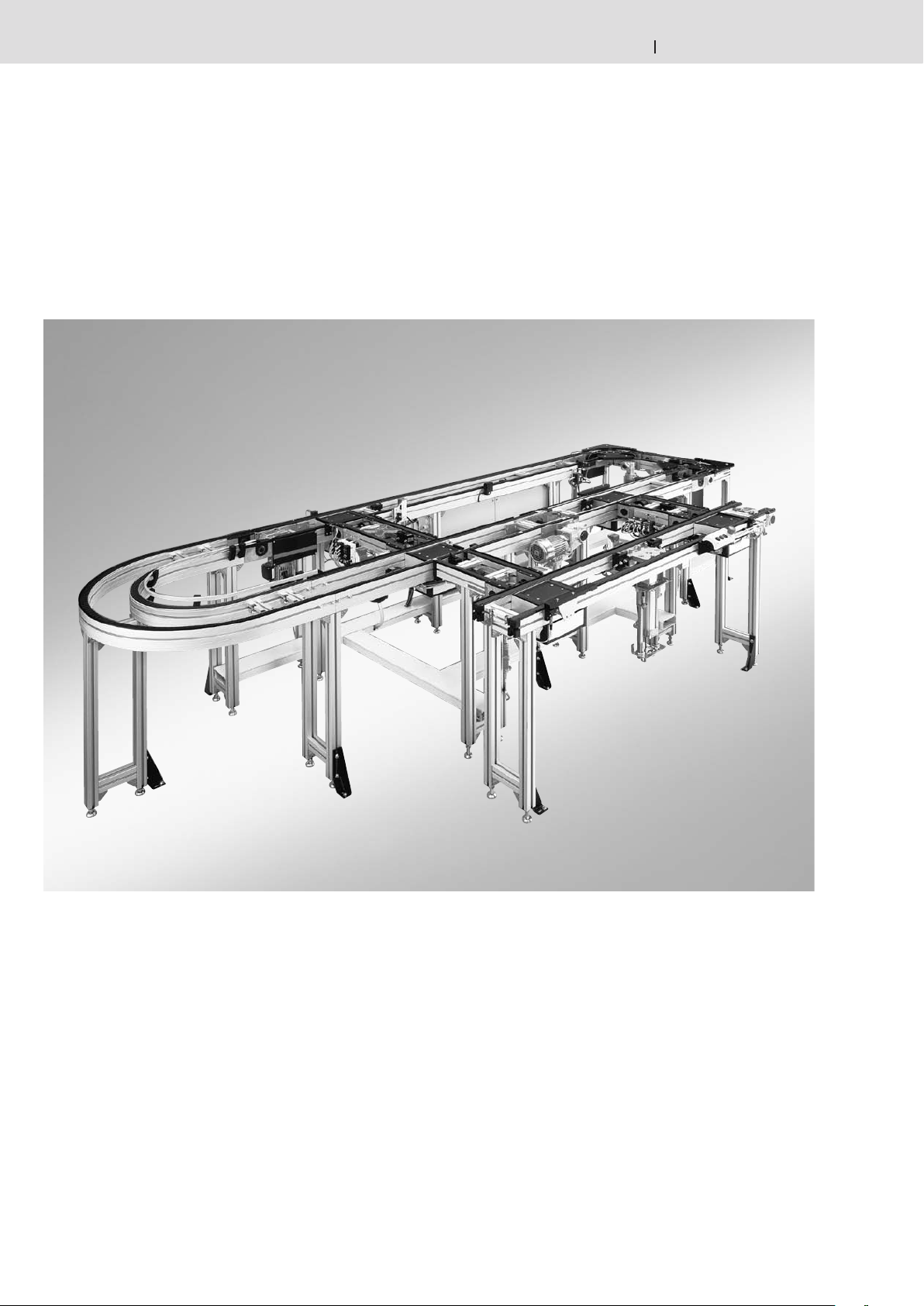
In einer Montagelinie werden mit Hilfe
eines Transfersystems Werkstücke von
Station zu Station befördert.
Auf zwei stetig umlaufenden Gurten,
Zahnriemen, Flachplattenketten oder
Staurollenketten oder Rundriemen
werden Werkstückträger (WT) über
Reibung mitgenommen. Die WT
nehmen die Werkstücke auf. Alle
Bearbeitungen erfährt das Werk stück
auf dem WT. Im Datenspeicher auf dem
WT werden Infor mationen über Ziele
und Bearbeitungszustände mitgeführt.
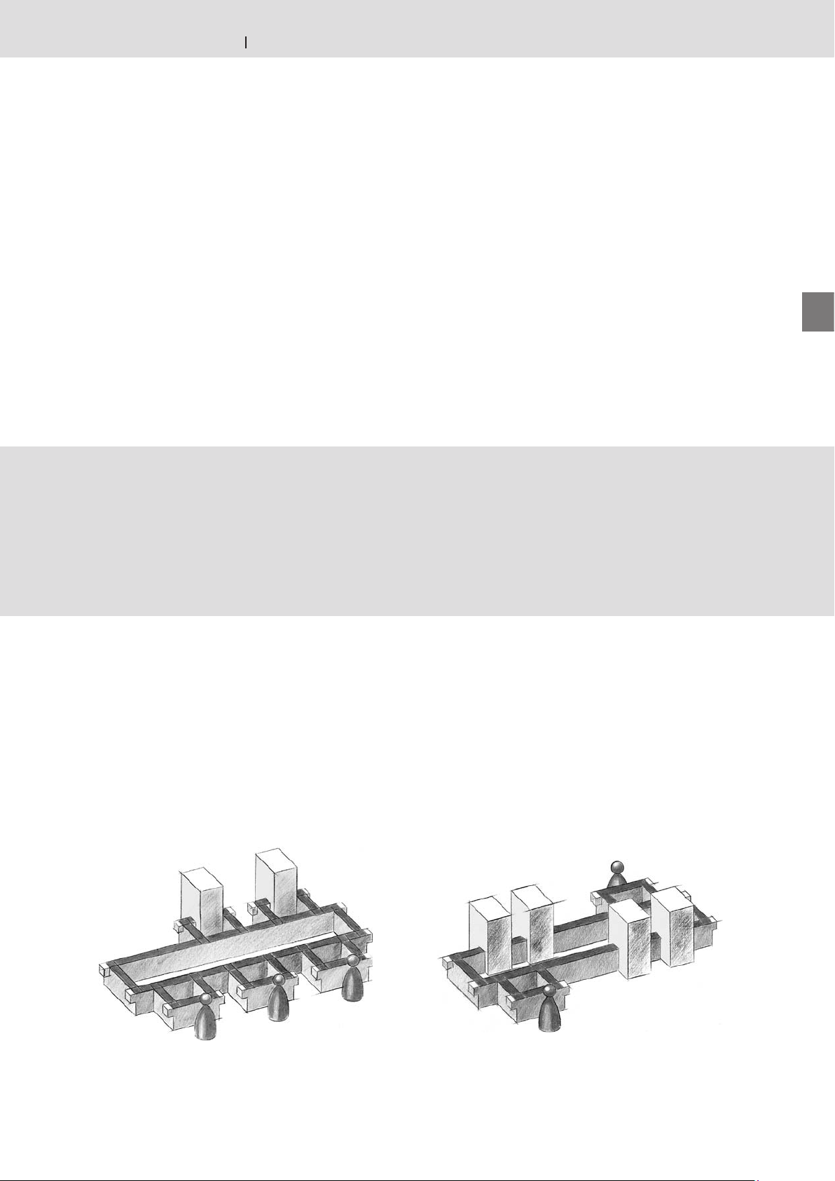
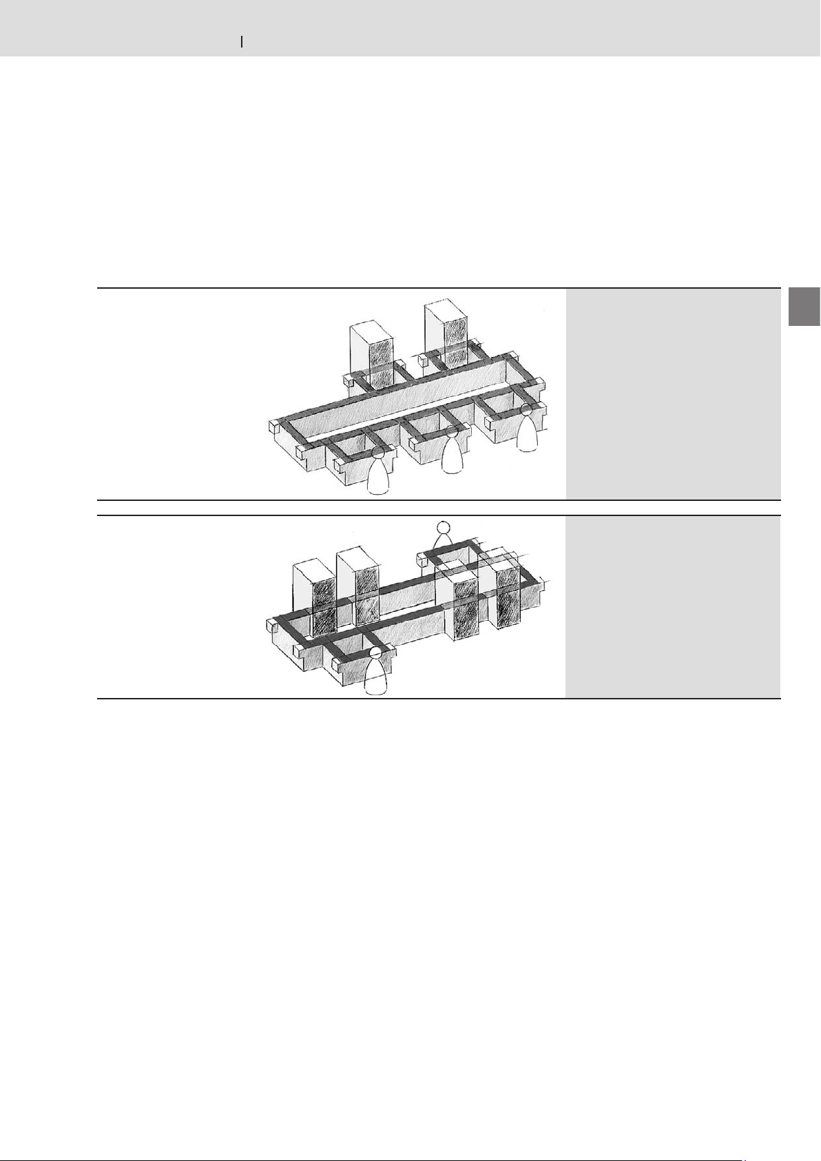
An den Stationen (Handarbeitsplätzen
oder Automatikstationen) wird der
WT durch Verein ze ler VE angehalten,
während das Fördermittel weiterläuft. Vor
einzelnen Stationen können mehrere WT
aufgestaut werden. Damit können kleine
Puffer gebildet werden. Nach beendetem
Arbeitsgang an der je weiligen Station
wird der WT für den Transport zur
nächs ten Ar beitsstation freigegeben.
Das Öff nen des pneumatischen VE
erfolgt dabei manuell oder durch eine
Stationssteuerung.
Am Ende des Montageablaufes wird das
fertig montierte Werkstück aus dem WT
entnommen.

On an assembly line workpieces have
to be transported from one station to
another using a transfer system.
Workpiece pallets (WT) are conveyed
by friction on two constantly moving
belts, toothed belts, flat top chains,
accumulation roller chains or rounded
belts. The workpiece pallets hold
the workpieces. A workpiece on the
workpiece pallets is transported through
all the processing stages. Information
about destination and processing
stage are carried in the workpiece
pallet memory. The workpiece pallet is
stopped by stop gates at stations (areas
for manual work or automatic stations),
while the conveyor continues moving.
Several workpiece pallets can be built up
in front of certain stations, to form small
buffers. Once the processing stage at
a station is completed, the workpiece
pallet is released to travel on to the
next work station. At the same time, the
pneumatic stop gate is opened, either
manually or with a station control.
At the end of the assembly process
the workpiece is removed from the
workpiece pallet.

Dans une chaîne de montage les pièces
sont transportées d’un poste à l’autre à
l’aide d’un système de transfert.
Des palettes porte-pièces (WT)
sont convoyées par friction sur deux
courroies de transport, courroies
dentées, chaînes à plate-formes,
chaînes à galets d‘accumulation ou
corroies rondes continuellement en
mouvement. Les palettes porte-pièces
servent à la réception des pièces. La
pièce est entièrement usinée sur la
palette porte-pièces. Les informations
concernant les destinations et l‘état
d‘usinage sont enregistrées dans la
mémoire de données sur la palette
porte-pièces. La palette porte-pièces est
stoppée aux postes de travail (postes de
travail manuel et postes automatiques)
grâce au séparateur VE pendant que
le convoyeur continue à avancer.
Plusieurs palettes porte-pièces peuvent
être accumulées devant un poste
permettant d‘en avoir quelques-unes
d‘avance. Une fois l‘opération terminée
au poste de travail correspondant, la
palette porte-pièce peut passer au
poste de travail suivant. L‘ouverture du
séparateur pneumatique VE se fait alors
soit manuellement, soit à l‘aide de la
commande poste.
En fin de chaîne de montage, la pièce
assemblée est enlevée de la palette
porte-pièce.
1
2
3
4
5
6
7
8
9
10
11
12
13
14
15
16
17
Bosch Rexroth AGTS 2plus 4.1 1–3
Eigenschaften TS 2plus · TS 2plus features · Caractéristiques TS 2plus
3 842 531 138 (2011.04)
Layoutplanung
Layout planning
Conception du schéma d‘implantation
Nebenschluss
Shunt
Circuit dérivé
Mischform
Mixed System
Forme mixte

Bei der Planung eines Anlagen-Layouts
spielt die Frage nach den individuellen
Anforderungen, Zielen und Zielprioritäten
des Unternehmens eine wichtige Rolle.
Komplexe Montageabläufe erfordern
häufig eine hohe Systemflexibilität
aufgrund:
– hoher Umrüsthäufigkeit
– variantenabhängiger
Abtaktungsprobleme
– unterschiedlicher Arbeitsinhalte in den
Stationen
– häufiger Erzeugnisänderungen
– starker Stückzahlschwankungen
In solchen Fällen ist ein Ausschleusen
der WT aus dem Hauptumlauf
(Hauptschluss) in taktunabhängige
Nebenschlussplätze sinnvoll.
Als Hauptschluss bezeichnet man die
Anordnung von Arbeitsplätzen/Stationen
in Reihe.
Nebenschluss ist das Ausschleu sen
von WT aus dem Hauptschluss zur
taktunabhängigen Bearbeitung mit
anschließendem Wiedereinschleusen in
den Hauptschluss.

When planning the layout of a system,
it is very important to enquire about the
individual requirements, targets and
priorities of a company. A very flexible
system is often required for complex
assembly procedures.
This may be due to:
– very frequent conversion
– cycle problems due to different
models
– differences in the work involved at
each station
– frequent product alterations
– great fluctuation in number of
workpieces
In cases like this, it is practical to
transfer the workpiece pallet off the
main conveyor (main circuit) into a shunt
system which is independent of the main
cycle.
The term main circuit is used to describe
workplaces or stations arranged in
series.
A shunt is when workpiece pallets
are directed out of the main circuit for
processing independently of the main
cycle, and then reintegrated in the main
circuit.

Lors de la conception du schéma
d'implantation d'une installation, les
besoins individuels, les objectifs et les
priorités d'une entreprise jouent un rôle
primordial. La complexité de certains
cycles de montage demande souvent
une grande flexibilité de la part du
système en raison de:
– des transformations très fréquentes
– des problèmes de concordance des
cadences différentes suivant les
variantes utilisées
– des différentes opérations réalisées
dans les postes de travail
– des changements fréquents de produit
– des variations importantes dans le
nombre de pièces
Dans ces cas là, il est utile de prévoir
une sortie de la palette porte-pièces du
circuit principaI dans un circuit dérivé
ayant sa propre cadence.
On désigne comme circuit principal
l‘alignement les uns à côté des autres
des postes de travail. Un circuit dérivé
est conçu pour dégager les palettes
porte-pièces du circuit principal, pour
un usinage à une autre cadence et
pour ensuite les remettre sur le circuit
principal.
Bosch Rexroth AG TS 2plus 4.11–4
Eigenschaften TS 2plus · TS 2plus features · Caractéristiques TS 2plus
3 842 531 138 (2011.04)
*Über Lifte beraten Sie unsere Partner.
*Our partners can advise you about lifts.
*Nos partenaires vous conseilleront
sur les élévateurs.
Anlagenlayouts
System layouts
Schémas d‘implantation des installations
Hauptschluss
Main circuit
Circuit principal
U-Form
U-shape
Forme en U
Linienbauweise (mit Lift*)
Linear construction (with lift*)
Construction en ligne
(avec élévateur*)
Karreebauweise
Rectangular circuit
Circuit carrée
U-Form (mit Lift*)
U-shape (with lift*)
Forme en U (avec élévateur*)
1
2
3
4
5
6
7
8
9
10
11
12
13
14
15
16
17
Bosch Rexroth AGTS 2plus 4.1 1–5
Eigenschaften TS 2plus · TS 2plus features · Caractéristiques TS 2plus
3 842 531 138 (2011.04)
Parallelarbeitsplätze
Parallel workplaces
Postes de travail en parallèle
Karreebauweise mit Parallel-
arbeitsplätzen
Rectangular circuits with
parallel workplaces
Circuits carrées avec postes
de travail en parallèle
Nebenschluss
Shunt
Circuit dérivé
Mischformen
Mixed systems
Formes mixtes
Bosch Rexroth AG TS 2plus 4.11–6
SZ 2
AS 2/R
BS 2
ST 2 UM 2/R
SZ 2
Eigenschaften TS 2plus · TS 2plus features · Caractéristiques TS 2plus
3 842 531 138 (2011.04)

Für kürzere Strecken

For short units

Pour des sections moins importantes

Für größere Strecken und Lasten

For long units and heavy loads

Pour des sections et des charges
plus importantes
Längstransport
Longitudinal conveyors
Transport longitudinal
Lösungsbeispiele
Design ideas
Suggestions
1
2
3
4
5
6
7
8
9
10
11
12
13
14
15
16
17
Bosch Rexroth AGTS 2plus 4.1 1–7
HQ 2
HQ 2
BS 2
RS 2
Eigenschaften TS 2plus · TS 2plus features · Caractéristiques TS 2plus
3 842 531 138 (2011.04)
WT-Umlauf
WT circuit
Circuit WT

Für parallele Umsetzung der
Werkstückträger

For parallel transfer of the pallets

Pour une transposition parallèle des
palettes

Für Karreebauweise

For rectangular circuits

Pour des circuits carrées
Bosch Rexroth AG TS 2plus 4.11–8
00013021.eps
HQ 2
HQ 2
ST 2
BS 2
HQ 2
HQ 2
UM 2
AS 2
SE 3
00013022.eps
Eigenschaften TS 2plus · TS 2plus features · Caractéristiques TS 2plus
3 842 531 138 (2011.04)
Systeme
Systems
Systèmes

Economical standard solution

Solution standard à un prix avantageux

Kostengünstige Standardlösung

Hohe Umbauflexibilität
(einfacher Austausch von Stationen)

Very versatile design
(simple to inter-change stations)

Construction facilement transformable
(en échangeant les postes de travail)
1
2
3
4
5
6
7
8
9
10
11
12
13
14
15
16
17
Bosch Rexroth AGTS 2plus 4.1 1–9
HQ 2
HQ 2
BS 2
BS 2
00013023.eps
Eigenschaften TS 2plus · TS 2plus features · Caractéristiques TS 2plus
3 842 531 138 (2011.04)

– Einfache Erweiterung der Anlage mit
zusätzlichen Stationen
– Hohe Wiederverwendbarkeit ganzer
Anlagenteile

– Simple extension of system with
additional stations
– High degree of reusability of whole
sections of the system

– Installation facile à agrandir en
ajoutant des postes supplémentaires
– Taux de réutilisation élévé de parties
entières de l’installation
Systeme
Systems
Systèmes
Bosch Rexroth AG TS 2plus 4.11–10
TS 2plus
TS 1
TS 5
Eigenschaften TS 2plus · TS 2plus features · Caractéristiques TS 2plus
3 842 531 138 (2011.04)
Transfersysteme – Übersicht
Transfer systems – overview
Systèmes de transfert – vue d‘ensemble

Material- und
Informationsflusstechnik MIT
Die Bezeichnung TS steht für flexibles
Transfersystem. Die Systeme
– TS 1, TS 2
plus
und TS 5 –
unterscheiden sich in Abmessungen und
zulässigen Traglasten.
Die Transfersysteme bestehen aus
standardisierten Baueinheiten,die
beliebig zu einem System kombinierbar
sind. Dies ermöglicht die Ausführung
zahlreicher Varianten und führt
zu maßgeschneiderten Anlagen,
abgestimmt auf die jeweilige
Montageaufgabe.

Material and information flow
technology MIT
The letters TS stand for a flexible transfer
system. The systems available
– TS 1, TS 2
plus
and TS 5
– differ in size and permissible load.
The transfer systems consist of
standardized components that are
freely combinable to form a system. This
permits the construction of numerous
variants and provides made-to-measure
systems, tailored to the particular
assembly task.

Technique de gestion du flux de
matériels et d`informations MIT
La dénomination TS est une abréviation
pour un système de transfert flexible.
Les systèmes – TS 1, TS 2
plus
et TS 5
– se différencient par leurs dimensions
et les charges admissibles. Les
systèmes de transfert sont composés de
composants standardisés, combinables
à volonté. Cela permet la construction
de nombreuses variantes et l’obtention
d’installations sur mesure, adaptées aux
besoins spécifiques de chaque montage.
1
2
3
4
5
6
7
8
9
10
11
12
13
14
15
16
17
Bosch Rexroth AGTS 2plus 4.1 1–11
ID 200
ID 15 ID 40
Eigenschaften TS 2plus · TS 2plus features · Caractéristiques TS 2plus
3 842 531 138 (2011.04)

Identifikations- und Datenträgersysteme
speichern alle produkt- und
prozessbezogenen Daten direkt am
Werkstückträger und ermöglichen deren
dezentrale oder zentrale Verarbeitung.

Identification and data storage systems
store all product and process-related
data directly on the workpiece pallet and
enable local or central data processing.

Les systèmes d’identification et de
supports de données enregistrent
l’ensemble des données relatives aux
produits et aux processus directement
sur la palette porte pièces et permettent
un traitement centralisé ou décentralisé.
Bosch Rexroth AG TS 2plus 4.11–12
TS 4plus
TS 5
TS 2plus TS 1
gk3
240
gk
250 kg
300 kg
Eigenschaften TS 2plus · TS 2plus features · Caractéristiques TS 2plus
3 842 531 138 (2011.04)
Auswahldaten
Selection data
Données de sélection

Verfügbare Werkstückträger (WT) -
Abmessungen
Werkstückträger mit einer Grund-
fläche von 80 x 80 mm (TS 1) bis
1243 x 1243 mm (TS 2plus) erlauben
die bedarfsgerechte Anpassung an die
entsprechende Werkstück-Geometrie.
Bei Bedarf können auch mehrere
Werkstücke auf einem Werkstückträger
(WT) fixiert werden.
Zulässige Werkstückträger (WT)
-Auflagegewichtskraft FWT
Um die zulässige Flächen pres sung
zwischen WT und Fördermittel nicht zu
überschreiten, ist für jede WT-Größe
die WT-Auflagegewichtskraft FWT
beschränkt.
Die WT-Auflagegewichtskraft FWT
resultiert aus:
– WT-Leergewicht
– WT-Zuladung (Werkstück, Aufnahme
etc.)
– Gewicht der Sonderausstattung
(Datenspeicher, etc.)
Bei nicht quadratischen Werkstückträgern
ist zu beachten, dass die zulässige WT-
Auflagegewichtskraft FWT im Längs- und
Quertransport unterschiedlich sein kann.

Available workpiece pallet (WT)
dimensions
Workpiece pallets with a surface
from 80 x 80 mm (TS 1) up to
1243 x 1243 mm (TS 2plus) allow for
the correct choice of workpiece pallet
for the particular workpiece geometry.
If necessary, a number of work pieces
can be accommodated on a single
workpiece pallet (WT).
Permissible loading weight for
workpiece pallet FWT
The workpiece pallet loading weight FWT
of each workpiece pallet size is limited
so that the permissible surface pressure
between the workpiece pallet and
conveying media is not exceeded.
The workpiece pallet loading weight FWT
consists of the following:
– the empty weight of the workpiece
pallet
– the weight supported by the work-
piece pallet (workpiece, holder, etc.)
– the weight of special equipment (data
storage, etc.)
For workpiece pallets that are not
square, please note that the permissible
WT loading weight FWT may be different
for longitudinal conveyors and transverse
conveyors.

Dimensions de palettes porte-pièces
(WT) disponibles
Des palettes porte-pièces dont
les dimensions sont comprises
de 80 x 80 mm (TS 1) jusqu’à
1243 x 1243 mm (TS 2plus) permettent
l’adaptation parfaite à la géométrie
spécifique de la pièce. Une seule palette
porte-pièces (WT) peut également
recevoir plusieurs pièces, en fonction
des besoins.
Force massique admissible de palette
porte-pièces FWT
Pour ne pas dépasser la force
superficielle admissible entre la palette
porte-pièces et le convoyeur, la force
massique FWT de la palette porte-pièces
est limitée pour chaque taille de palette
porte-pièces.
La force massique FWT de palette
porte-pièces résulte :
– du poids propre de la palette
porte-pièces
– de la charge de la palette porte-pièces
(pièce à usiner, support, etc.)
– du poids des équipements spécifiques
(support mobile de données, etc.)
Pour des palettes porte-pièces non
carrées, noter que la force massique
autorisée de palette porte-pièces
FWT peut différer en cas de transport
longitudinal et transversal.
1
2
3
4
5
6
7
8
9
10
11
12
13
14
15
16
17
Bosch Rexroth AGTS 2plus 4.1 1–13
F =
WT
^
Eigenschaften TS 2plus · TS 2plus features · Caractéristiques TS 2plus
3 842 531 138 (2011.04)
Systemkenngrößen
System parameters
Grandeurs caractéristiques du système

Zulässige Streckenbelastung FG zul.
Bei der Auslegung der Förderstrecken
ist darauf zu achten, dass die
Summe FG aller Werkstückträger-
Auflagegewichtskräfte FWT , die sich
gleichzeitig auf der Förderstrecke
im Stau befinden, kleiner ist als die
zulässige Streckenbelastung der
Förderstrecke FG zul.
Wird die zulässige Streckenbelastung
FG zul. der Förderstrecke dabei über-
schritten, muss diese in mehrere
Einzelstrecken unterteilt werden.
Die zulässige Streckenbelastung
der einzelnen Förderstrecken ist den
Einzelbeschreibungen zu entnehmen.

Permissible section loading FG zul.
When designing the conveyor sections,
it is important to ensure that the total
mass FG of the loading weight of all
workpiece pallets FWT which are on
the conveyor section in accumulation
operation at one time is below the
permissible load for conveyor
sections FG zul.
If this permissible load FG zul. for the
conveyor section is exceeded, the
section must be divided into several
individual sections. The permissible
section loading of the individual
conveyor sections can be determined
from the individual descriptions.

Charge de section admissible FG zul.
Lors de la conception des sections de
transport, veillez à ce que le total FG
des forces massiques de toutes les
palettes porte-pièces FWT se trouvant
sur un même convoyeur en accumulation
soit inférieur à la charge maximale
admissible des convoyeurs FG zul.
Si ce total dépasse la charge maximale
autorisée du convoyeur FG zul. il doit
être réparti sur plusieurs sections.
Vous trouverez la charge de section
admissible dans la description détaillée
de chaque convoyeur.
Bosch Rexroth AG TS 2plus 4.11–14
bL
bQ
Eigenschaften TS 2plus · TS 2plus features · Caractéristiques TS 2plus
3 842 531 138 (2011.04)

Längstransport, Quertransport
Das Transportniveau des Quertransports
liegt über dem des Längs transports. Die
Haupttransportrichtung einer Anlage ist
der Längstransport.

Transport longitudinal, transport
transversal
Le niveau de transport transversal
est supérieur à celui du transport
longitudinal. Le sens principal de
transport d‘une installation est celui
longitudinal.

Longitudinal conveyor, transverse
conveyor
The transport level of transverse con-
veyor is above that of the longitudinal
conveyor. A system‘s main direction
of transportation is the longitudinal
conveyor.

Spurbreite
Die Spurbreite b ergibt sich
direkt aus den entsprechenden
Werkstückträger-Abmes sun gen
bWT und lWT. Daher ist zu beachten,
dass bei rechteckigen (also nicht
quadratischen) Werkstückträgern die
Spurbreiten b für Längstransport und
Quertransport unterschiedlich sind.

Track width
The track width b is directly related
to the workpiece pallet dimensions
bWT and lWT. For this reason, the
conveyor track widths b are different
for the longitudinal and transverse
conveyors if the workpiece pallet is
rectangular, i.e. not square.

Ecartement de la voie
L‘écartement de la voie b est
calculé à partir des dimensions
correspon dantes de la palette
porte-pièces bWT et lWT. C‘est
pourquoi, les écartements de la voie
b de la section pour les transports
longitudinales et transversales sont
différent si la palette porte-pièces
est rectangulaire (c’est à dire pas
carrée).
Systemkenngrößen
System parameters
Grandeurs caractéristiques du système
1
2
3
4
5
6
7
8
9
10
11
12
13
14
15
16
17
Bosch Rexroth AGTS 2plus 4.1 1–15
Eigenschaften TS 2plus · TS 2plus features · Caractéristiques TS 2plus
3 842 531 138 (2011.04)

Zulässige Schwerpunktlage
Um die Beschleunigungskräfte bei
Vereinzelung oder Richtungsänderungen
(Kurven, Wechsel in die
Quertransportrichtung) störungsfrei
aufnehmen zu können, ist die Lage des
Beladungsschwerpunktes auf dem
Werkstückträger zu beachten.
Generell empfehlen wir:
1. die Werkstückträger möglichst mittig
zu belasten
2. den Beladungsschwerpunkt
in der Höhe hS nicht über
1/2 bWT (mit bWT ≤ lWT)
hinauskommen zu lassen

Position admissible du centre de
gravité
Afin de pouvoir supporter les forces
accélératrices lors de séparation ou
modifications de direction (courbes,
changement dans la direction de transport
transversal) sans défaut, il faut faire
attention à la position du centre de gravité
de la charge sur la palette porte-pièces.
En generale nous conseillons :
1. de charger la palette porte-pièces le
plus au centre possible
2. de ne pas laisser le centre de gravité
de la charge dépasser dans la hauteur
hS 1/2 bWT (avec bWT ≤ lWT)

Permissible gravity center position
When separating pallets or changing
directions (curves, change in the
transverse conveyor direction), it is
important to observe the position of the
gravity center load on the workpiece
pallet to ensure that the acceleration
forces can be absorbed without any
interferences.
Generally we recommend that:
1. The load should be positioned in the
center of the workpiece pallet
2. The center of gravity should
not exceed a height hS of
1/2 bWT (with bWT ≤ lWT)
Bosch Rexroth AG TS 2plus 4.11–16
Eigenschaften TS 2plus · TS 2plus features · Caractéristiques TS 2plus
3 842 531 138 (2011.04)

Verwendete Materialien,
Medienbeständigkeit
Die Rexroth-Transfersysteme werden
für den Dauereinsatz aus hochwertigen
Materialien hergestellt. Sie sind
beständig gegen die in normaler
Industrieumgebung üblicherweise
vorkommenden Schmier- und
Pflegemittel. Im Rahmen dieses
Kataloges kann jedoch keine Gewähr
für die Beständigkeit gegenüber allen
möglichen Kombinationen an Prüffluiden,
Gasen oder Lösemitteln übernommen
werden. Bitte erkundigen Sie sich
hierzu im Zweifelsfall bei Ihrer Rexroth-
Fachvertretung.
Verwendbarkeit in elektrostatisch
gefährdeten Bereichen
Nahezu alle Komponenten und Bauteile
der Rexroth-Transfersysteme sind
leitfähig beziehungsweise in leitfähiger
Ausführung erhältlich. Sie sind damit
grundsätzlich für den Einsatz in EPA
(ESD Protected Areas – elektrostatisch
gefährdeten Bereichen) geeignet.
Im Einzelfall empfehlen wir hierzu
die Rücksprache mit Ihrer Rexroth-
Fachvertretung.

Materials used, resistance to media
Rexroth transfer systems are
manufactured with high-quality materials
to ensure continuous use. They are
resistant to lubricating and cleansing
agents that are common in an industrial
environment. However, we cannot
guarantee that the products contained
in this catalog are resistant to all
combinations of testing liquids, gases,
or solvents. Please contact your Rexroth
representative if you have any doubts.
Suitability for electrostatically
sensitive areas
Almost all of the components and
parts in Rexroth transfer systems
are ESD-compatible or available in
ESD-compatible design. They can
thus principally be used in EPA (ESD
protected areas). We do, however,
recommend that you contact your
Rexroth representative.

Matériaux utilisés, résistance
chimique
Les systèmes de transfert Rexroth
sont fabriqués pour l‘utilisation de
longue durée à partir de matériaux de
haute qualité. Ils sont résistants aux
matières lubrifiantes et aux produits
d‘entretien rencontrés d‘habitude dans
un environnement industriel normal.
Dans le cadre de ce catalogue, aucune
garantie ne peut toutefois être donnée
pour la résistance vis-à-vis de toutes
les combinaisons possibles de fluides
d‘essai, gaz ou solvants. Dans le doute,
veuillez vous renseigner sur ce point
auprès de votre représentant spécialisé
Rexroth.
Utilité pratique dans les zones
sensibles aux décharges
électrostatiques
Presque tous les composants et
éléments de construction des systèmes
de transfert Rexroth possèdent une
capacité de décharge électrostatique
ou sont disponibles en version avec
capacité de décharge électrostatique.
Ils sont ainsi essentiellement
appropriés pour l‘utilisation en EPA
(zones protegées contre décharges
électrostatiques). Au cas par cas, nous
conseillons sur ce point un entretien
préliminaire avec votre représentant
spécialisé Rexroth.
Systemkenngrößen
System parameters
Grandeurs caractéristiques du système

This manual suits for next models

1

Other REXROTH Industrial Equipment manuals

REXROTH WT2 Setup guide

REXROTH

REXROTH WT2 Setup guide

REXROTH Sytronix FcP 5020 User manual

REXROTH

REXROTH Sytronix FcP 5020 User manual

REXROTH HAB Series User manual

REXROTH

REXROTH HAB Series User manual

REXROTH TS 2plus User manual

REXROTH

REXROTH TS 2plus User manual

REXROTH HAB Setup guide

REXROTH

REXROTH HAB Setup guide

Popular Industrial Equipment manuals by other brands

RM C GP3-1 operating instructions

RM

RM C GP3-1 operating instructions

Trumpf TRUPUNCH 5000 Operator's manual

Trumpf

Trumpf TRUPUNCH 5000 Operator's manual

Balluff BIC 1I22-P2A02-M18MN2-EPX07-050 installation guide

Balluff

Balluff BIC 1I22-P2A02-M18MN2-EPX07-050 installation guide

3M 3M-Matic 8000af Instructions and parts list

3M

3M 3M-Matic 8000af Instructions and parts list

NovoPress SLB 120 Repair instructions

NovoPress

NovoPress SLB 120 Repair instructions

Shel lab SCO58 Installation and operation manual

Shel lab

Shel lab SCO58 Installation and operation manual

Holex 362175 instruction manual

Holex

Holex 362175 instruction manual

Matatakitoyo Torque Tools MT2-4000N Operation manual

Matatakitoyo Torque Tools

Matatakitoyo Torque Tools MT2-4000N Operation manual

Binks A12846 Series product manual

Binks

Binks A12846 Series product manual

Hofmann geodyna 6300 instructions

Hofmann

Hofmann geodyna 6300 instructions

X-Rite PANTONE Judge QC Operation manual

X-Rite

X-Rite PANTONE Judge QC Operation manual

Nederman MagnaTrack S user manual

Nederman

Nederman MagnaTrack S user manual

Rohde & Schwarz MDS-21 user manual

Rohde & Schwarz

Rohde & Schwarz MDS-21 user manual

CLEAN ROOM DEVICES CRD600 Operation manual

CLEAN ROOM DEVICES

CLEAN ROOM DEVICES CRD600 Operation manual

kosmek WVA quick start guide

kosmek

kosmek WVA quick start guide

Pasco Scientific WA-9401 Instruction manual and experiment guide

Pasco Scientific

Pasco Scientific WA-9401 Instruction manual and experiment guide

Tronair 01-0400-0000 Operation & service manual

Tronair

Tronair 01-0400-0000 Operation & service manual

TMG TMG-SLG30 product manual

TMG

TMG TMG-SLG30 product manual

manuals.online logo
manuals.online logoBrands
  • About & Mission
  • Contact us
  • Privacy Policy
  • Terms and Conditions

Copyright 2025 Manuals.Online. All Rights Reserved.