English (GB)
2
English (GB) Installation and operating instructions
Original installation and operating instructions
CONTENTS
These installation and operating instructions describe MAGNA3.
Sections 1-5 give the information necessary to be able to unpack,
install and start up the product in a safe way.
Sections 6-13 give important information about the product, as
well as information on service, fault finding and disposal of the
product.
Page
1. General information
1.1 Symbols used in this document
The text accompanying the three hazard symbols DANGER,
WARNING and CAUTION is structured in the following way:
1. General information 2
1.1 Symbols used in this document 2
1.2 Safety symbols on the pump 3
2. Receiving the product 3
2.1 Inspecting the product 3
2.2 Scope of delivery 3
2.3 Lifting the pump 4
3. Installing the product 4
3.1 Location 4
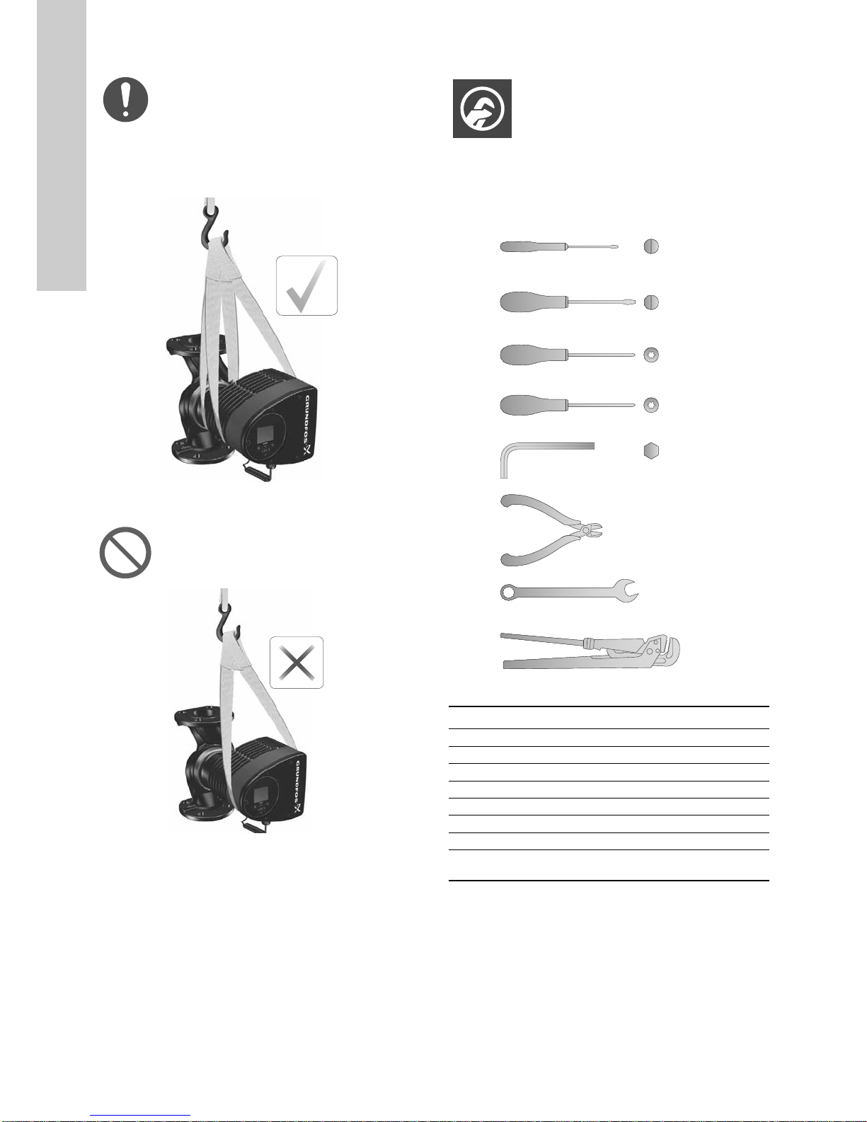
3.2 Tools 4
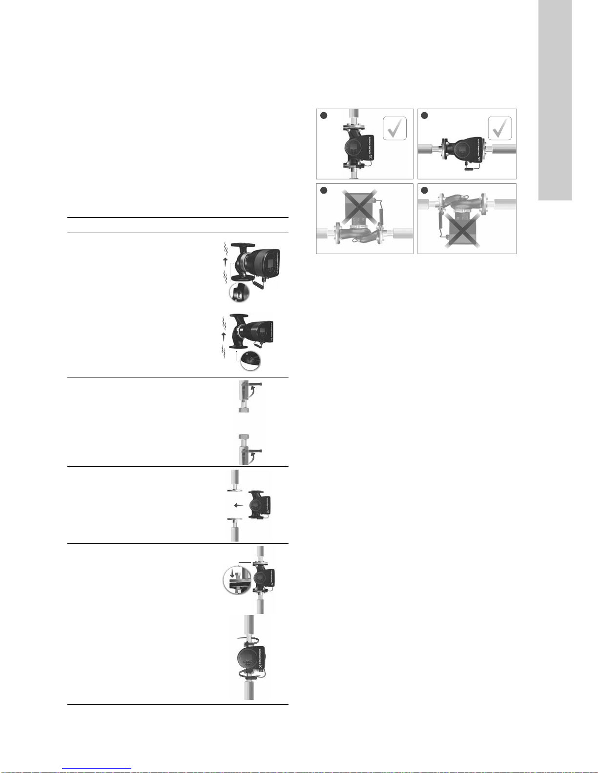
3.3 Mechanical installation 5
3.4 Positioning the pump 5
3.5 Control box positions 6
3.6 Pump head position 6
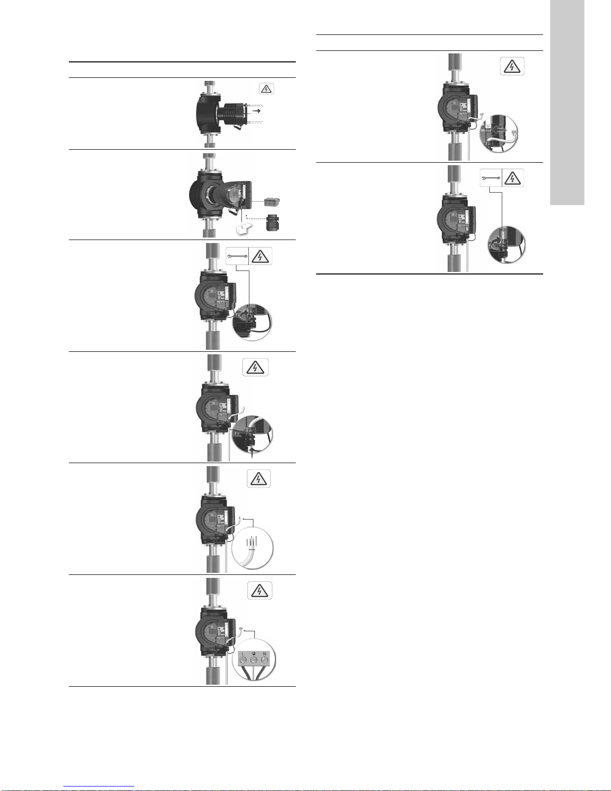
3.7 Changing the control box position 7
3.8 Electrical installation 8
3.9 Connecting the power supply 9
4. Starting up the product 12
4.1 Single-head pump 12
4.2 Twin-head pump 13
5. Storing and handling the product 13
5.1 Frost protection 13
6. Product introduction 13
6.1 Applications 13
6.2 Pumped liquids 13
6.3 Identification 14
6.4 Model type 15
6.5 Radio communication 15
6.6 Insulating shells 15
6.7 Non-return valve 15
7. Control functions 16
7.1 Overview of settings 16
7.2 External connections 17
7.3 Input and output communication 18
7.4 Priority of settings 18
8. Setting the product 21
8.1 Operating the product 23
8.2 "+RPH" menu 23
8.3 Menu overview 24
8.4 6WDWXV menu 26
8.5 "2SHUDWLQJVWDWXV"26
8.6 "6HWWLQJV" menu 26
8.7 Setting values for control modes 33
8.8 "$VVLVW" menu 38
8.9 External setpoint influence 41
8.10 Flow estimation accuracy 41
8.11 Pump heads in twin-head pumps 41
8.12 "'HVFULSWLRQRIFRQWUROPRGH"42
8.13 "$VVLVWHGIDXOWDGYLFH"42
8.14 Wireless GENIair 42
9. Servicing the product 43
9.1 Differential-pressure and temperature sensor 43
9.2 External sensor condition 43
10. Fault finding the product 44
10.1 Grundfos Eye operating indications 44
10.2 Fault finding 45
11. Accessories 47
11.1 Grundfos GO 47
11.2 Communication interface module, CIM 47
11.3 Counterflanges 52
11.4 External sensors 52
11.5 Cable for sensors 52
11.6 Blanking flange 53
11.7 Insulating kits for air-conditioning and cooling systems 53
12. Technical data 53
12.1 Sensor specifications 54
13. Disposing of the product 54
Prior to installation, read this document and the quick
guide. Installation and operation must comply with
local regulations and accepted codes of good
practice.
This appliance can be used by children aged from 8
years and above and persons with reduced physical,
sensory or mental capabilities or lack of experience
and knowledge if they have been given supervision
or instruction concerning use of the appliance in a
safe way and understand the hazards involved.
Children shall not play with the appliance. Cleaning
and user maintenance shall not be made by children
without supervision.
DANGER
Indicates a hazardous situation which, if not avoided,
will result in death or serious personal injury.
WARNING
Indicates a hazardous situation which, if not avoided,
could result in death or serious personal injury.
CAUTION
Indicates a hazardous situation which, if not avoided,
could result in minor or moderate personal injury.
SIGNAL WORD
Description of hazard
Consequence of ignoring the warning.
- Action to avoid the hazard.
A blue or grey circle with a white graphical symbol
indicates that an action must be taken.
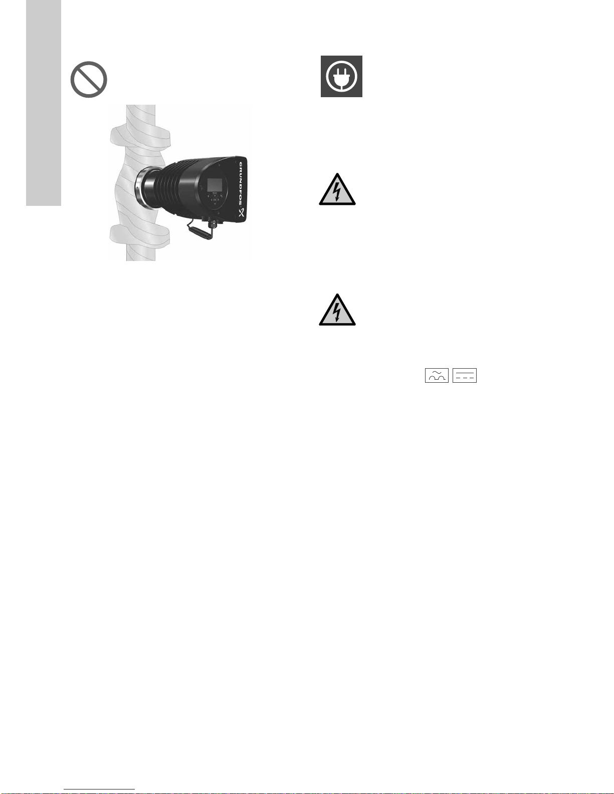
A red or grey circle with a diagonal bar, possibly with
a black graphical symbol, indicates that an action
must not be taken or must be stopped.
If these instructions are not observed, it may result in
malfunction or damage to the equipment.
Notes or instructions that make the work easier and
ensure safe operation.