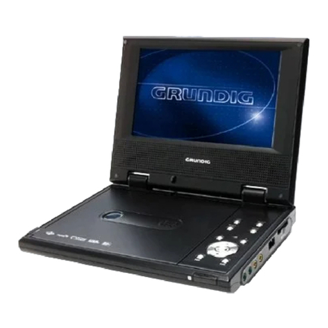
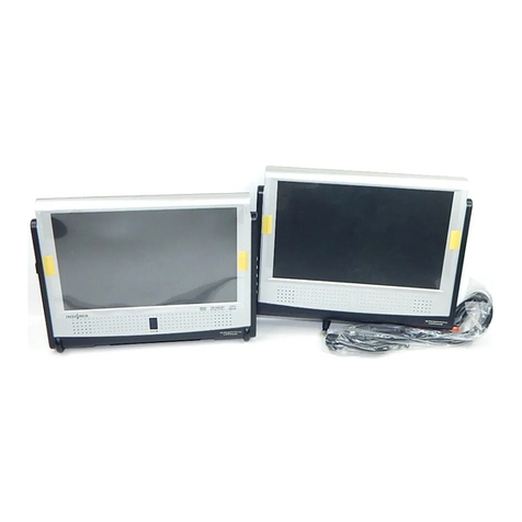
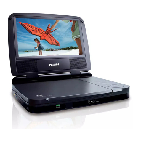
Grundig DVD-P 8600 User manual

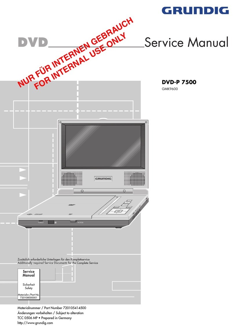
DVD Service Manual
Zusätzlich erforderliche Unterlagen für den Komplettservice
Additionally required Service Documents for the Complete Service
Service
Manual
Sicherheit
Safety
Materialnr./Part No.
720108000001
DVD-P 8600
GML1900
DVD-P 8600/2
GML3800
NUR FÜR INTERNEN GEBRAUCH
FOR INTERNAL USE ONLY
Materialnummer / Part Number 720105416500
Änderungen vorbehalten / Subject to alteration
TCC 0207 MP • Prepared in Germany
http://www.grundig.com

GRUNDIG Service DVD-P 8600…
1 - 2
Table of Contents
Page
General Section .................................. 1-2…1-10
General Notes ...............................................................................1-2
Technical Data...............................................................................1-3
Software Upgrade..........................................................................1-3
Operating Hints..............................................................................1-7
Layout of the PCBs
and Circuit Diagrams ......................... 2-1…2-16
Block Circuit Diagram ....................................................................2-1
Main Board ....................................................................................2-2
– Power Supply ............................................................................2-4
– Rechargeable Battery................................................................2-5
– Audio..........................................................................................2-6
– Interface.....................................................................................2-7
– USB/Card Reader......................................................................2-7
DVD Board.....................................................................................2-8
– Voltage Supply.........................................................................2-10
– Processor.................................................................................2-10
– Interface...................................................................................2-12
– Memory....................................................................................2-12
Display Board ..............................................................................2-13
– Processor.................................................................................2-14
– Power Supply...........................................................................2-15
– Inverter .....................................................................................2-15
Keyboard .....................................................................................2-16
Exploded View
and Spare Parts List...................................... 3-1
Inhaltsverzeichnis
Seite
Allgemeiner Teil .................................. 1-2…1-10
Allgemeine Hinweise .....................................................................1-2
Technische Daten..........................................................................1-3
Software-Upgrade .........................................................................1-3
Bedienhinweise .............................................................................1-4
Platinenabbildungen
und Schaltpläne.................................. 2-1…2-16
Blockschaltplan..............................................................................2-1
Hauptplatte ....................................................................................2-2
– Netzteil.......................................................................................2-4
– Akku...........................................................................................2-5
– Audio..........................................................................................2-6
– Interface.....................................................................................2-7
– USB/Card-Reader......................................................................2-7
DVD-Platte.....................................................................................2-8
– Spannungsversorgung.............................................................2-10
– Prozessor.................................................................................2-10
– Interface...................................................................................2-12
– Speicher...................................................................................2-12
Display-Platte ..............................................................................2-13
– Prozessor.................................................................................2-14
– Netzteil.....................................................................................2-15
– Inverter .....................................................................................2-15
Keyboard .....................................................................................2-16
Explosionszeichnung
und Ersatzteilliste.......................................... 3-1
Es gelten die Vorschriften und Sicherheitshinweise
gemäß dem Service Manual "Sicherheit", Material-
nummer720108000001,sowiezusätzlichdieeventuell
abweichenden, landesspezifischen Vorschriften!
Theregulations and safety instructionsshall be valid
as provided by the "Safety" Service Manual, part
number 720108000001, as well as the respective
national deviations.
General Section
General Notes
Before opening the cabinet disconnect the mains plug!
Attention: Observe the ESD safety regulations
Wiring
Before disconnecting any leads and especially the earth connecting
leads observe the way they are routed to the individual assemblies.
On completion of the repairs the leads must be laid out as originally
fitted at the factory to avoid later failures or disturbances.
Carrying out Measurements
Whenmakingmeasurementsonsemi-conductorswithanoscilloscope,
ensure that the test probe is set to 10:1 dividing factor. If the previous
measurement was made on AC input, please note that the coupling
capacitor in the oscilloscope will be charged. Discharge via the item
being checked can damage the components.
Measured Values
The measured values given in the circuit diagrams are approxi-
mates!
Allgemeiner Teil
Allgemeine Hinweise
Vor dem Öffnen des Gehäuses den Netzstecker ziehen!
Achtung: ESD-Vorschriften beachten
Leitungsverlegung
Bevor Sie die Leitungen und insbesondere die Masseleitungen lösen,
muss die Leitungsverlegung zu den einzelnen Baugruppen beachtet
werden.
Nach erfolgter Reparatur ist es notwendig, die Leitungsführung wieder
in den werkseitigen Zustand zu versetzen um evtl. spätere Ausfälle
oder Störungen zu vermeiden.
Durchführen von Messungen
Bei Messungen mit dem Oszilloskop an Halbleitern sollten Sie nur
Tastköpfe mit 10:1 -Teiler verwenden.Außerdem ist zu beachten, dass
nach vorheriger Messung mit AC-Kopplung der Koppelkondensator
des Oszilloskops aufgeladen sein kann.Durch die Entladung über das
Messobjekt können Bauteile beschädigt werden.
Messwerte
Bei den in den Schaltplänen angegebenen Messwerten handelt es
sich um Näherungswerte!
GRUNDIG Service DVD-P 8600…
1 - 3
Technische Daten
Allgemein
Netzspannung:......................... AC 100…240VAC (50/60Hz) Adapter
Eingebauter Akku: ........................................................ Lithium-Ionen
Nennleistungsaufnahme:..................................................13,5V, 1,2A
Umgebungstemperatur:...........................................+10°C bis +35°C
LCD-Bildschirm ..........................................................LG 8” TFT 16:9
DVD-Player-Player
Wiedergabe-Norm .......................................... PAL, 50Hz, 625 Zeilen
Bildformat .............................................................................4:3, 16:9
Wiedergabe-System......................................................... DVD-Video
Audio-CD (CD-DA)
CD-R, CD-RW
CD ROM (MP3/JPEG/DivX/Nero),
Sampling Frequenz 44,1kHz
Abmessungen B x H x T.................................. 226 x 39,5 x 166mm
Gewicht .....................................................................................962g
Software-Upgrade
– Neue Software auf eine CD brennen.
– CD im DVD-P 8600 einlegen und Hinweise am Display beachten.
Achtung: Während des Updates keine Tasten drücken oder die
Spannungsversorgung unterbrechen, da sonst der Speicher auf
der Hauptplatte zerstört werden kann.
Gewährleistung
Wir weisen ausdrücklich darauf hin, dass nur von GRUNDIG frei-
gegebene System-Software zulässig ist. Wurde als Fehlerursache
festgestellt, dass eine aus nicht legitimierten Quellen gleich welcher
Herkunft stammende oder eine veränderte System-Software in die
Geräte geladen wurde, so ist dies ein Fremdeingriff. Ein Fremdeingriff
führt zum Erlöschen jeglicher Gewährleistungsansprüche.GRUNDIG
muss daher alle aus diesen Gründen resultierenden Kostenerstattun-
gen generell ablehnen. Instandsetzungskosten, auch innerhalb der
Gewährleistungszeit, gehen in diesen Fällen zu Lasten des Händlers
bzw. des Endkunden.
Technical Data
General informationinformation
Mains voltage .........................AC 100…240V AC (50/60Hz) Adapter
Built-in battery .................................................................. Lithium-ion
Rated power consumption................................................13.5V, 1.2A
Ambient temperature.................................................+10°C to +35°C
LCD screen.................................................................LG 8” TFT 16:9
DVD player
Playback standard .............................................PAL, 50Hz, 625 lines
Picture format .......................................................................4:3, 16:9
Playback system................................................................DVD Video
Audio CD (CD-DA)
CD-R, CD-RW
CD ROM (MP3/JPEG/DivX/Nero),
sampling frequency 44.1kHz
Dimensions W x H x L...................................... 226 x 39.5 x 166mm
Weight .......................................................................................962g
Software Upgrade
– Burn the new software on a CD.
– Insert the upgrade CD in the DVD-P 8600 and observe the hints onDVD-P 8600 and observe the hints onand observe the hints on
the display.
Attention: Don't press any key and don't interrupt power while
software is supgrading, otherwise, the memory of the main board
may be destroyed.
Warranty / costs
We expressly point out that only operating software authorized by
GRUNDIG is allowed. If a failure is caused by an operating software
which has been downloaded from not authorized sources, indepen-
dent of its origin, or by a modified software, this represents an outside
interference. An outside interference leads to the expiration of any
warranty claims. For this reason, GRUNDIG is obliged to generally
refuse any payment due to such infringements. In such cases, the
repair costs are at the charge of the retailer or the final customer, even
within the period of warranty.
Schrauben / Screws!

GRUNDIG Service DVD-P 8600…
1 - 4
Bedienhinweise Dieses Kapitel enthält Auszüge aus der Bedienungsanleitung.
Weitergehende Informationen entnehmen Sie bitte der gerätespezifischen Bedienungsanleitung, deren Materialnummer Sie in der entsprechenden Ersatzteilliste finden.

GRUNDIG Service DVD-P 8600…
1 - 5

GRUNDIG Service DVD-P 8600…
1 - 6

GRUNDIG Service DVD-P 8600…
1 - 7
Operating Hints This chapter contains excerpts from the operating instructions.
For further particulars please refer to the appropriate user instruc-
tions the part number of which is indicated in the relevant spare

GRUNDIG Service DVD-P 8600…
1 - 8

GRUNDIG Service DVD-P 8600…
1 - 9

GRUNDIG Service DVD-P 8600…
1 - 10

Platinenabbildungen und Schaltpläne / Layout of PCBs and Circuit Diagrams
Blockschaltplan / Block Circuit Diagram
LCD
DV D
PORT
VIDEO
DECODE
TCON
(T101) 8”
DIGITAL
PANEL
DC TODC
(6615 & 6608)
D
VIDEO
FILTER
AUDIO
AMP
SDRAM
MT1389HD
EEPROM
24C04
SPEAKER
DRIVER
Speaker Out
Headphone Out
FLASCH
BA5954&BA6849
PICH UP
4060/1410/9141
DC-DC
3.3V
1.8V
5V
FE TE Driver
VIDEO OUT L/R OUT
27MHz
8 Bit
16 Bit
FOCUS TRACK
SLED SPINDLE
9V IN
C TO AC
(mps1029)
656
SDA
SCL
RG B
T-CON
3.3V
2.5V
AVDD
VGH
VGL
13.5V
13.5V
BL_EN
DVD
GRUNDIG Service DVD-P 8600…
2 - 1

Hauptplatte / Main Board
Ansicht von der Bestückungsseite / View of Component Side
GRUNDIG Service DVD-P 8600…
2 - 2

Hauptplatte / Main Board
Ansicht von der Lötseite / View of Solder Side
GRUNDIG Service DVD-P 8600…
2 - 3

Hauptplatte – Netzteil / Main-Board – Power Supply
VCC3
IR
R1 0
47K
L17
FB / 0805
R2 7
10K
Q2
2307
1
23
D14
1N4148
GND
+33V
R131
10K
QP 2
UT CL D1117/ NC /TO-252
1
3 2
ADJ
IN OUT
BC20
0.1u F
GND
C470 .22uF
D1
1N4148
R130
30K
EC 21
47uF/16V
VC C3 [2,3,4]
RP 2 4.7k
DISC HA R
CH AR GE _L ED
ON SW
DC
VCC3
U8
1410
1
2
3
4 5
6
7
8
BS
Vin
Vs w
GNDF B
Comp
EN
Sy nc
ON SW
UR ST O# [2]
Q4
3904
1
3 2
L2 FB / 0805
EC 24
100u F/ 16V
+5V
DISC HAR
[5]
DC_IN [2]
GND
GND
DV D_O FF
J1
DC JA CK(+9V ~+12V
1
2
3
GND
GND
CHAR
LE D1
1
2
3
DC_IN
OV ER
GND
DC_IN
GND
9V _I N
RP 5
150R
DC_IN
L19F B / 0805
+18V
+18V
GND
C46
0.01u F
DISC HAR
9V _M ON IT OR
BC11
0.1u F
R128
27k
EC 23
47uF/16V
CH_IN
DC_IN
R1 5
10k
GND
C45
0.01u F
R129
10K
DC_IN
BC10
0.1u F
EC 26
47uF/16V
EC 5
100u F/ 16V
2 1
CH AR GE _L ED
[5]
CHAR
CH_IN
+33V
VC C3 [2,3,4]
R136
10K
Q27
3904
1
3 2
D13
1N4148
GND
VCC3
IR 2
R2 0
18K
9V _I N
R134
100K
R7
10K
GND
ON SW [2]
+5V
L1 6 22u H/1. 2A (S MD6)
RP 4
270R
L1 22u H/1. 2A(S MD 6)
9V _I N [2,3]
DC
9V _I N
R1 2
100k
R127
47k
GND
ON SW
CP 1
0.1u F
U7
1410
1
2
3
4 5
6
7
8
BS
Vin
Vs w
GNDF B
Comp
EN
Sy nc
R125
200K
BC21
0.1u F
RP 1 NC
Q6
3904
1
3 2
R135
10K
EC 25
47uF/16V
R1 6
1.5K
C48
0.01u F
UR ST O#
ON SW
C43
0.01u F
DV D_O FF
RB 1
4.7K
GND
CHAR [5]
EC 27
47uF/16V
VCC3
+5V
GND
R1 9
30K
R1 14 .7K
Q5
SI2307
1
23
EC 20
47uF/16V
+5VC ON20/SMT/A
ON SW
Q8
3904
1
3 2
+33V [2,4]
R132
10K
GND
QP 1
3904
1
3 2
GND
+18V [2]
RP 3
10k
L1 8 22u H/1. 2A(S MD 6)
U9
1410
1
2
3
4 5
6
7
8
BS
Vin
Vs w
GNDF B
Comp
EN
Sy nc
BC8
0.1u F
GND
D5
SS1 4
1 2
GND
GND
R126
200K
LP
1.8V Power for DSP Kernel
1
FB / 0805
C190 .22uF
Q26
2307
1
23
BC9
0.1u F
F1
2A_F US E
L4
FB
VCC3
C6
0.01u F
IR [2,3]
9V _M ON IT OR
9V _M ON IT OR
Q7
3904
1
3 2
GND
DV D_O FF
OV ER
R8
10K
DV D_O FF
C440 .22uF
R1 34 .7K
R1 4
4.7K
+18V
VCC3
CH AR GE _L ED
DC
DP 1
15v
1 2
EC 22
100u F/ 16V
C8
0.01u F
R6
100K
MP1410
Σ
40/400KHz
Oscillator
Slope
Compensation
1.8V
Current
Comparator
Internal
Regulators
2
1uA
2.30/2.53V
0.7V
7
Shutdown
Comparator
Lockout
Comparator
3
4
M2
M1
6
1.22V
5
Error Amplifier
gm= 630uA/Volt
IN
EN
COMP
FB
GND
SW
BS
1
0.7V
Frequency
Foldback
Comparator
5V
CLK
S
R
Q
Q
Current
Sense
Amplifier
GRUNDIG Service DVD-P 8600…
2 - 4

R117 1M
R116
5K1
Q23B
4953
3
4
5
6
R98
4K7
R86
10R
R960.25
R92470R
IC3
TL431
1
2
3
R10510K
C29
4.7UF
C38
0.1UF
BT1
C304.7UF
IC4
S-8254
1
2
3
4
5
6
7
8 9
10
11
12
13
14
15
16
L11 100UH
C42
1UF
C32
0.1UF
R106 10K
QF3
2412
IC2
4953
1
2
3
4 5
6
7
8
R124
0
R122
0
C HAR
C33
0.1UF
R851K
C36
0.1UF
B -
R793 .3K
R104 30K
DIS CHAR
R10010K
R84
4K7
B -
R81 470R
B +
Q20
1037
R941K
Q19
2412
C2810UF
C40
0.1UF
C HA RG E_LE Dto page2
R87220K
R950.25
Q23A
4953
1
2
7
8
CB6220UF
D3
SK34
12
RF21 1.5K
C350.1UF
B -
R118
1K
C34
0.1UF
F2 1.25A
P3
Q22
NPN
R123
0
B +
R107
47R
BT4
R89 10K
R119
1K
C37
0.1UF
R93 22K
R99OPEN
R1010.25
C310.1UF
R115
5K1
R833 K3
R80
1K(0805)
R121
0
CF2
0.1UF
Q18
2412
R108
470R
R109 2K2
R102
OPEN
BT3
Q21
2412
U6A
LM-358
1
2
3
4
P2
R120
1K
R773 K3
R970.25
P5
R82
10R
C41
0.1UF
R112
20K
C39
0.1UF
R900.25
Y1
8M
R103
30k
R111
20K
DF1
SS14
1 2
D12SS14
ICF2
9454
1
2
3
4
5
6
7
8
9
10 11
12
13
14
15
16
17
18
19
20
BT2
CF9
0.1UF
R9147K
R78
3.3K
P4
Hauptplatte – Akku / Main Board – Rechargeable Battery
S3C9442/C9444/F9444/C9452/C9454/F9454
Timer 0
ADC
PWM
X
IN
X
OUT
OSC
Basic
Timer
ADC0-ADC8
P0.6/PWM
Port 0
Port 2
Port 1
P0.0/ADC0/INT0
P0.1/ADC1/INT1
P0.2/ADC2
P0.7/ADC7
...
P1.0
P1.1
P1.2
P2.0/T0
P2.1
P2.6
...
88RCRI
SAMRI CPU
Port I/O and
Interrupt Control
2 KB ROM
4 KB ROM
208 Byte
Register file
GRUNDIG Service DVD-P 8600…
2 - 5

LMAIN1
R43 47K
CVBSO[ 2]
R62 10K
J2
1
2
3
R29
10K
EC11
10uF/16V
CVBSO
AL
R113 1K
C23 330P(NC)
VCC3
CE4
100uF/10V
D7
1N4148
1 2
R59 270K
D_MUTE[2]
R66 470
R88
0
A_VCC
J7
4PIN/1.25mm(TO SPEAKE
R)
1
2
3
4
AR[2]
AL
BC5
0.1uF
A_R_SPEAKER
MR_IN/OUT
R39
100
R47
1(0805)
R55
1K
J8
2
1
ML IN
VCC3
R_HP_IN
L_HP_IN
OUT_L
C12
2200p
EC8 10uF/16V
C18
330P
9V_IN
A_MUTE
MR IN
R251 K
R58
1(0805)
AUD_GND
AR
A_R_SPEAKER
J4
E PORT
1
2
3
4
5
6
7
8
9
10
11
12
13
14
15
16
17
18
R64
4.7R
GND
AR
R35 47K
RA3 100
D_MUTE
U5
APA2822
1
2
3
4
5
6
7
8
Q13
3906
1
32
Q12
SI2307
1
23
SW
R65
4.7R
EC14
10uF/16V
9V_IN
Q10
3904
1
3 2
MR_IN/OUT
SW
R21
20k
R401 K
A_VCC
MR IN
R37
10k
RA2 100
R49
100K EC17
100uF/16V
RMAIN1
F3
FUSE 1.25A
R63 270K
C13
100uF/16V
C2
10uF/16V
A_R_SPEAKER
A_L_SPEAKER
VER
9V_IN
[1]
ML_IN/OUT
L12
22UH
C3
10uF/16V ML_IN/OUT
EC10
10uF/16V
Q15
3906
1
32
PHONE_L
L9
1.8UH
AL[2]
+5V
EC16
100uF/16V
R53 100K
SW
EC19
10uF/16V
C10
10uF/16V
9V_IN
C22 330P(NC)
AUD_GND
+5V[1]
A_MUTE
D6
1N4148
1 2
A_L_SPEAKER
R461 K
R133
1K
R61 10K
OUT_R
R51
1k
J6
CON4_2
2
1
SP_R
CVBSO
Q14
3904
1
3 2
R22
10k
R56 330
9V_IN
R310
D_MUTE
ML_IN/OUT
D8 1N4148
1 2
AUD_GND
LMAIN1
Q25
3904
1
3 2
R50 10K
DP2
5V1
12
R210
7K5
C11
10uF/16V
EC7
100uF/16V
D101 N4148
1 2
OUT_R
R57
4.7K
EC12
10uF/16V
VCC3[1]
C17
330P
CVBSO
MR_IN/OUT
J5
PHONE-JACK
1
2
3
4
5
6
7
8
9
10
11
R33
0
D111 N4148
1 2
R_HP_IN
R450
EC13
100uF/16V
GND
A_MUTE
RA4 1K
ML_IN/OUT
Q17
3904
1
3 2
AUD_GND
CVBS IN
R30
1(0805)
BC7
0.1uF
IR
PHONE_R
A_MUTE
U3A
NJM4558
3
2
1
8 4
EC18
100uF/16V
R24
100
EC9 10uF/16V
IR
[1,2]
RMAIN1
R28 10K
Q11
3904
1
3 2
R23
5.1k
SW[2]
R41
680K
VJ1
VOLUME 10K
1
2
3
4
5
1
2
3
4
5
A_MUTE
C16
10uF/16V
Q16
3904
1
3 2
R60 470
C14
100uF/16V
OUT_R
C5
100uF/10V
IR
C15
0.1uF
R52
1k
A_L_SPEAKER
L13F B
EC15
100uF/16V
MR_IN/OUT
R320
U3B
NJM4558
5
6
7
8 4
L_HP_IN
TVCC
CB2
0.1uF
RA6N C
R42
47K
SP_L
ML IN
R44 470
R211
7K5
RA5N C
OUT_L
SP_L
D9
1N4148
1 2
9V_IN
OUT_L
C9
220p
SP_R
R34
20k
R54 330
AV_1
1
2
GND
CVB R L
3
4
5
R26
100K
VCC3
R36
0
VCC3
VER
TVCC
BC6
0.1uF
R38
5.1k
R48
4.7K
+5V
C1
220p
CVBS IN
RA1 1K
U4 4053
1
2
3
4
5
6
7
8
16
15
14
13
12
11
10
9
Y1
Y0
Z1
Z
Z0
INH
VEE
VSS
VDD
Y
X
X1
X0
A
B
C
C4
2200p
L1
L2
R1
R2
GND
SW1
SW2
Hauptplatte / Main-Board – Audio
GRUNDIG Service DVD-P 8600…
2 - 6

AL
B C13 220P
HVE NO
K X4 O
U SB M
SDD2
VC C 3
R141 33
SDD0
9V_MONITO R
+18V
R142 33
SDD3 [4]
DC_IN [1]
S W [3]
+33V [1] G ND
B C16 220P
SDD3
K X3 O
U SB P [4]
+18V
URS TO #
K Y3 O
G ND
K X4 O
VC C 3 [1]
R140 33
+5V
K X1 O
B C15 220P
U SB P
SDD1
G ND
DC_IN
B C18 220P
ON S W [1]
9V_IN [1]
ON S W
AR [3]
B C19 22 0P
C VB SO [3]
U SB M [4]
G ND
J 2
1
2
3
4
5
6
7
8
9
10
11
12
13
C VB SO
+33V
S DC MD [4]
K Y4 O
G ND
AL
ON S W
+5V
SDD2
SDD0
E C6
10 0UF /2 5V
C ARDDET [4]
S DC MD
S W
D_MU TE [3]
+5V [1]
R138 33
DC_IN
K X2 O
B C14 220P
K Y2 O
9V_MONITO R
SDD0 [4]
B C17 220P
S DC LK
+33V
IR
C VB SO
G ND
IR
K Y3 O
R139 33
SDD2 [4]
SDD3
C ARDDET
G ND
S W
B C12 220P
G ND
G ND
D_MU TE
AR
C ON 1
2
1
3
4
5
6
7
8
9
10
11
12
13
14
15
16
17
18
19
20
21
22
23
24
25
26
27
28
29
30
31
32
33
34
35
36
37
38
+18V
K X1 O
S DC MD
URS TO # [1]
9V_MONITO R
+5V
+5V
R143 33
AR
U SB M
+18V [1]
IR [1]
G ND
SDD1 [4]
B C4
0.1UF
AL [3]
K Y4 O
R145 33
K Y1 O
S DC LK
C ARDDET
+5V
9V_IN
HVE NO
J 3
1
2
3
4
5
6
7
8
9
10
11
12
L8
22UH
SDD1
R144 33
S DC LK [4]
K X3 O
K Y1 O
K Y2 O
K X2 O
+33V
D_MU TE
U SB P
+5V
USBM [2]
R 71 10k
SDD1
S DC MD
C E3
47 uF /1 6v
U SB VC C
C 27
20pF
C E2
47 uF /1 6v
R 73 33
SDD1
R 69 10k
R 68 10k
C B3
0.1uF
R 76
15K
+5V [ 1]
SDD0
R 67 10k
S DC MD [ 2]
SDD3 [2]
SDC LK
USBP [2]
F 4
F US E
+33V
SDD3
SDD0
R 72 10k
SDD3
C 24
20pF
SDD0 [2]
+5V
C B4
0.1uF
C ON3
S D/MMC C AR D
1
2
3
4
5
6
7
8
9
10
11
G 1
G 2G 3
G 4
D3
C MD
VSS
VDD
C LK
VSS
D0
D1
D2
INS _S W
WP_SW
G
GG G
C ARD DET
U SB M
SDD1 [2]
R 70 10k
S DC MD
R 75
15K
SDD2
U SB M
C 25
20pF
S DC LK
R 74 33
+33V [1]
U SB VC C
U SB P
C ARD DET [2 ]
P 1
USB T YP EA
3
2
1
4
56
S DC LK [2]
U SB P
L15 F B
SDD2 [2]
SDD2
C 26
20pF
+33V
C ARD DET
1: GND
2: D+
3: D–
4: VCC
Hauptplatte / Main Board – Interface
Hauptplatte / Main Board – USB / Card-Reader
GRUNDIG Service DVD-P 8600…
2 - 7

DVD-Platte / Board
Ansicht von der Bestückungsseite / View of Component Side
GRUNDIG Service DVD-P 8600…
2 - 8

DVD-Platte / Board
Ansicht von der Lötseite / View of Solder Side
GRUNDIG Service DVD-P 8600…
2 - 9

DVD-Platte – Spannungsversorgung / DVD Board – Voltage Supply
1
DVD-Platte – Prozessor / DVD Board – Processor
2
BA5954
OET2
OET1
+
+
THERMAL
SHUT DOWN -BY
STAND
SLED
+
12
13
14
10
11
6
7
5
4
3
2
1
8
9
19
15
17
16
18
21
20
23
22
24
26
25
28
27
DRIVER
ACTUATOR
DRIVER
ACTUATOR
DRIVER
DRIVER
LOADING
Vcc PV cc2 PV cc1
X2
X2
DET AMP.
DET AMP.
VINFC
CFCerr1
CFCerr2
V
VOSL
VNFFC
Vcc
PV
PGND
VOSL-
VOSL+
VOFC-
VOFC+ VOTK+
VOTK-
VOLD+
VOLD-
PGND
VNFTK
PV
BIAS
GND
V LD
CTKerr2
CTKerr1
V TK
STBY
SL+
IN
SL-VIN
IN
IN
CC2
10K 20K
7.5K
7.5K
7.5K
10K
15K
Pre GND
PGND
PV CC2
25K
10K
PGND
Vcc
CC1
CC1
PV
7.5K
20K 10K
GRUNDIG Service DVD-P 8600…
2 - 10
Other manuals for DVD-P 8600
1
This manual suits for next models
3
Table of contents
Other Grundig Portable DVD Player manuals

Grundig
Grundig DVD-P 7000 User manual

Grundig
Grundig DVD-P 7600 User manual

Grundig
Grundig DVD-P 7644 User manual

Grundig
Grundig DVD-P 7850 User manual

Grundig
Grundig DVD-P 7600 User manual

Grundig
Grundig GMK9600 User manual

Grundig
Grundig DVD-P 7000 User manual

Grundig
Grundig DVD-P 8600 User manual

Grundig
Grundig DVD-P 8600/2 User manual

Grundig
Grundig DVD-P 7850 User manual