GSi 1 Series User manual

Chain Conveyor
Incline Chain Conveyor
Series 1
Installation and Operation Manual
PNEG-1056

- 2 -
This manual contains information that is important for you, the owner/operator, to know and
understand. This information relates to protecting personal safety and preventing
equipment problems. It is the responsibility of the owner/operator to inform anyone
operating or working in the area of this equipment of these safety guidlines.To help you
recognize this information, we use the symbols that are defined below.
Please read the manual and pay attention to these sections. Failure to read this manual
and it’s safety instructions is a misuse of the equipment and may lead to serious injury or death.
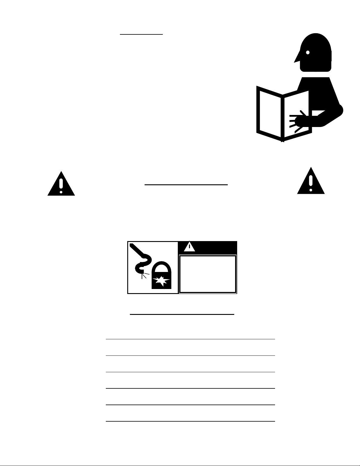
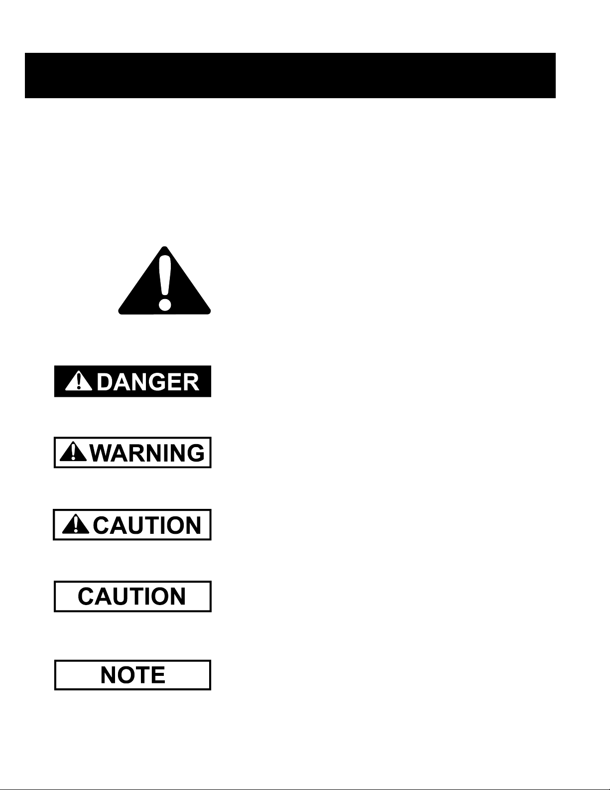
SAFETY GUIDELINES
This is the safety alert symbol. It is used to alert you
to potential personal injury hazards. Obey all
safety messages that follow this symbol to avoid
possible injury or death.
DANGER indicates an imminently hazardous situation
which, if not avoided, will result in death or serious injury.
WARNING indicates a potentially hazardous situation
which, if not avoided, could result in death or serious injury.
CAUTION indicates a potentially hazardous situation which,
if not avoided, may result in minor or moderate injury.
CAUTION used without the safety alert symbol indicates a
potentially hazardous situation which, if not avoided, may
result in property damage.
NOTE indicates information about the equipment that you
should pay special attention to.

- 3 -
TABLE OF CONTENTS
EQUIPMENT INFORMATION................................................................... 4
SAFETY DECAL LOCATIONS………………………………………….. 5
GENERAL PRECAUTIONS..................................................................….. 11
RECEIVING AND PRE-INSTALLATION................................................ 12
INSTALLATION………............................................................................... 13
CARE, MAINTENANCE, STORAGE......................................................... 21
OPTIONS...................................................................................................…. 25
TROUBLE SHOOTING………………………………………………….. 29
TRAINING SIGN OFF SHEET………………………………………….. 30
MAINTENANCE RECORD……………………………………………… 31
WARRANTY………………………………………………………………. 32

- 4 -
Introduction
We encourage all personnel operating, installing, or maintaining this
equipment to thoroughly read this manual before proceeding. Successful
operation is our intention; however, if in fact you are in need of technical
advice or support, we encourage you to contact your local dealer/distributor
or contact the factory at any time during regular business hours at 217-226-
4421. Our commitment is to you the customer, and we encourage your input
and/or suggestions that would help better our product.
This manual covers general information on incline conveyor (straight and
bend incline configurations) installation. Due to the varying sizes of
equipment it would be very difficult to cover every aspect of installation. We
offer one method for erecting conveyors but many times the contractor’s
experience and techniques will work. Many times conditions and
surroundings do not allow certain practices during the erection of
equipment. We cannot be responsible for the erection of the conveyor
(unless so contracted to do so).
Safety Information
It is the responsibility of the buyer to make this manual available to the person
or persons involved with this equipment. Guards and safety labels have been installed prior to the
equipment leaving the manufacturing plant. These devices are not to be removed, altered, or defaced,
otherwise voiding any liability or responsibility of the manufacturer. Power lock out is very important prior
to installation, adjustment, and maintenance of the unit.
Equipment Information
Model Number:
Serial Number:
Date Purchased:
Dealer/Distributor:
Operator’s
Manual
DANGER
Disconnect and
Lockout Electric
Power Before
Servicing Unit

- 5 -
Head Section Decal Locations
1.

- 6 -
Tail Section Decal Locations
1.

- 7 -
Trough Section Decal Location
2.

- 8 -
Bend Section Decal Location
2.

- 9 -
Bypass Inlet Decal Location
2.

- 10 -
Bypass Dump Hopper Decal Location
2.

- 11 -
CAUTION
1. Do not operate the unit before reading and understanding the
operator’s manual.
2. Keep all safety shields and devices in place.
3. Make certain everyone is clear of the equipment before operating or moving
the machine.
4. Keep hands, feet, and clothing away from moving parts.
5. Shut off and lock out all power to adjust, service, clean,
or unclog.
6. Keep off the equipment at all times.
7. Keep children, visitors, and all untrained personnel away
from machine while in operation.
8. Do not operate electric motor equipped units until motors are properly
grounded.
9. Disconnect power on electrical driven units before resetting motor overloads.
10. Do not repetitively stop and start the drive in order to free a plugged
condition. Jogging the drive in this type of condition can damage the conveyor
and/or drive components.

- 12 -
SET-UP INSTRUCTIONS
This manual is provided by the company to aid in the assembly, operation, and maintenance of
its conveyors. Should a question arise concerning the assembly or operation of this unit not
covered by this manual, please contact the company at 217-226-4421 during regular business
hours and ask for assistance.
In this manual, right and left are determined by standing behind the unit and facing toward the
drive section (See figure below).
UNPACKING
Carefully inspect the shipment as soon as it is received. Verify that the quantity of parts and
packages corresponds to the quantity shown on the packing slip. Any discrepancies should be
clarified immediately. Please remember that any damage or missing parts must be noted on the
bill of lading at the time of delivery. Report any damage or shortages to the delivering carrier as
soon as possible. The company’s responsibility for damage to the equipment ends with the
acceptance by the delivering carrier. It is not the responsibility of the company to file claims for
damages with the appropriate carrier.
Save all paper work and documentation furnished with any of the chain conveyor
components.

- 13 -
Installation
The following guidelines dealing with the installation of the Series I incline conveyors are
provided for your convenience. The company cannot be held responsible for the installation of
this unit.
Clearance
A clearance of at least the width of the conveyor is recommended on all sides of the unit. This
amount of clearance is not a necessity; less clearance maybe acceptable. However, serious
consideration must be given to methods of maintenance, removal and replacement of the
conveyor and/or its parts.
Support & Welding
No welding of any kind on or to the conveyor is recommended. Welding on or to the conveyor
may cause damage to both the conveyor and its electrical system. If welding is necessary, the
manufacturer prefers that the attachments or supports be welded to bottom splices. Should it be
necessary to fasten anything to the conveyor permanently, careful consideration should be given
to methods of maintenance, removal and replacement of the conveyor and/or its parts.

- 14 -
Head Section
The head section of the conveyor is shipped pre-assembled from the factory. Each head
section has a tag with serial number. There are sub-assembly instructions in the care and
maintenance section of this manual.
Tail Section
The tail section of the conveyor is shipped pre-assembled from the factory. Each tail section has
a tag with serial number. There are sub-assembly instructions in the care and maintenance
section of this manual.

- 15 -
Trough Assembly
Intermediate trough sections come both factory pre-assembled or unassembled. Your order
will serve as a reference to how your trough section should arrive.
Assembly sequence for trough sections unassembled:
Fasten trough bottom panel to each trough side panel using 3/8” hex head bolts and 3/8” whiz
nuts. Whiz nuts should be located on bottom side of conveyor. The trough bottom panel should
extend beyond trough side panels approximately two inches on one end and recessed
approximately two inches on the other end.
Fasten center pan, with flange up, using 3/8” carriage bolts through holes provided in trough
side panels. At the seams the carriage bolts below the center pan should be welded to the trough
side panels. Heads of carriage bolts should be inside the conveyor. For liner package assembly
check options portion of this manual.
Conveyor Assembly
Remove trough covers from trough sections to aid the conveyor assembly.
Position a head, tail or other intermediate trough section with holes in bottom flange of trough
sides aligned with holes in bottom panel of another section. Using a bottom splice, (4) 3/8” bolts
and (4) 3/8” whiz nuts fasten the two sections together. The bottom splice should cover the gap
between the two bottom panels, which is offset two inches from the gap in the trough sides.
Position trough splices over the gap between the end of the trough sections and fasten with 3/8”
carriage bolts and 3/8” whiz nuts.
Discharge
The standard conveyor is constructed with one discharge located at the drive end. Attach the
discharge transition to the bottom of the conveyor head using 3/8” bolts and 3/8” whiz nuts.

- 16 -
Drive Package Assembly
Using hardware provided, attach motor mount angles to
motor mount adapter. There are only two motor mount
angles on reducers up to a 3 7/16” bore. For reducers with 3
15/16” bore and larger there are four motor mount angles.
Attach motor base to motor mount adapter using
all-thread rods (4) and nuts (16) provided in hardware
package. (Note orientation of motor base.)
Attach this assembly to the reducer, using the existing
bolts in the reducer. The angles should be mounted on the
same side as the input shaft.
Remove any rust, paint or imperfections from the drive
shaft. The drive shaft must be clean and shiny before
installing the reducer drive.
Slide the reducer bushing onto the shaft.
Mount the reducer onto the drive shaft and fasten in place
using the reducer bushing and cap screws provided. Do not
tighten the bushing cap screws until the end of the drive
shaft is protruding through reducer at least a 1/8”. Make
sure adequate space remains between the bearing and the
reducer bushing to allow removal of the bushing cap screws.

- 17 -
Attach torque arm channel to bottom of conveyor. Some holes
may have to be field drilled in bottom panel to attach torque arm
channel. The position of the torque arm channel depends on the
incline of the head. When the head is on the incline desired the
reducer should still be vertical. The torque arm channel should be
placed so the torque arm from the reducer can reach when reducer
is in the vertical position.
Connect the adjustable torque arm from the reducer to the
torque arm channel. Make sure torque arm is mounted on the side
of reducer nearest to the torque arm channel. The torque arm
should be mounted parallel to the conveyor side.
Fasten the motor to the motor mount with hardware provided.
Connect the conveyor motor to a power source according to the
motor manufacturer’s instructions and recommendations. Due to
the hazards involved with electricity, it is recommended that an
electrician perform the motor wiring. A shut off switch should be
placed near the motor so that the system may easily be shut down
to help prevent accidents during maintenance.
Attach upper belt guard bracket and lower belt guard bracket to
reducer with hardware provided. The upper bracket should be
mounted to the upper holes in the motor mount adapter. The
lower bracket is two pieces. The two pieces should be mounted
together at slotted holes and then mounted to the reducer.

- 18 -
Place the rear belt guard panel onto the reducer
drive shaft and the motor shaft. Attach to the upper
and lower brackets with hardware provided.
Remove any rust, paint or imperfections from the
motor shaft. Install the motor sheave and sheave
bushing on the motor shaft.
Remove any rust, paint or imperfections from the
reducer drive shaft. Install the reducer sheave
and sheave bushing on the reducer drive shaft
Align the reducer sheave and the motor sheave.
With both sheaves aligned tighten all hardware.
Place the drive belts provided on the sheaves.
Adjust the all-thread on motor base to tighten
according to the instructions provided with reducer.
Proper belt tension is 1/64”of deflection per one (1“)
inch of sheave centers on one side of the belt, centered
between sheaves. (See figure 1)
Position front belt guard cover into the rear belt
guard panel and attach using the clips mounted on belt
guard panel.
Check lubricant level in the reducer before operation.
Follow manufacturer recommendations for reducer
lubrication.

- 19 -
Chain
All chain is shipped in approximate 10 foot lengths. The UHMW wiper flights should be in
front of the welded chain flights in the direction of chain travel (see diagram).
Adjust take-up screws to position the take-up sprocket as far from the end of the conveyor as
possible. Assemble all of the sections of chain using the connecting links provided with chain
assembly. With the assembled conveyor mounted in its permanent position, install the chain
assembly in the bottom of the conveyor and wrap chain around the sprocket at the head and tail
of the conveyor. Using a ratchet cable puller, pull the two ends of the chain together. Remove
the unneeded chain and fasten the two ends together using a connecting link furnished with the
chain assembly. Adjust take-up screws to tighten the chain.
81X Chain Assembly 4” Pitch Roller Chain Assembly

- 20 -
Cover
Rope or silicone caulk should be used on all surfaces where the trough covers splices come in
contact with the trough covers. Bolt all of the trough cover panels in place using 3/8” bolts and
3/8” whiz nuts. Leave the end bolt holes open on each trough cover for the installation of the
cover splices. Install the cover splices over the gaps in the trough covers using 3/8” bolts and
3/8” whiz nuts.
Inlet Assembly
Inlets mounted too close to the tail chain sprockets will allow grain to come in contact with the
sprocket and chain pinch. This may cause excessive damage to any grain being conveyed. The
minimum distance from the tail splice joint to the nearest edge of the inlet assembly should be
equal to the inlet opening plus 2 inches (A + 2” in Figure 2).
The angle iron guard in the middle of the inlet assembly should be in position to divert flowing
grain from the chain links.
When the proper position for the inlet is determined, a full conveyor width opening should be
cut into the conveyor cover. Another opening should be cut in the center pan. The opening
should start at the edge of the inlet and extend a distance of twice the inlet opening, towards the
tail. The width of the opening should be determined by starting the opening a distance of 1 ¼”
from inside edge of conveyor. (See Figure 2)
Using the inlet assembly provided, drill 7/16” holes in the top flange of the conveyor trough
sides.
Fasten the inlet assembly in place using 3/8” bolts and 3/8” whiz nuts.
Use the same caulking material for the inlet assemblies that was used for the trough cover
panels.
Figure 2
Table of contents
Other GSi Accessories manuals
Popular Accessories manuals by other brands

Philips
Philips P-5722-C Specifications

enware
enware ENM620 Installation, operating, & maintenance instructions

Mustang Survival
Mustang Survival MD3090 owner's manual

Burster
Burster 8402 Series Technical product information

Baumer
Baumer FECK 07P6901/KS35A manual

Nevadent
Nevadent NZR 1.5 A1 operating instructions