manuals.online logo
Brands
  1. Home
  2. •
  3. Brands
  4. •
  5. GSi
  6. •
  7. Electric Heater
  8. •
  9. GSi VH-E Series User manual

GSi VH-E Series User manual

Popular Electric Heater manuals by other brands

Heatrex 240 Series owner's manual

Heatrex

Heatrex 240 Series owner's manual

U-Line H-6100 quick start guide

U-Line

U-Line H-6100 quick start guide

EINHELL QHT 1500 operating instructions

EINHELL

EINHELL QHT 1500 operating instructions

CONVECTAIR FOR Installation and user guide

CONVECTAIR

CONVECTAIR FOR Installation and user guide

Kogan KAHTP20BLKA quick start guide

Kogan

Kogan KAHTP20BLKA quick start guide

Black & Decker STANLEY ST-02-230-E manual

Black & Decker

Black & Decker STANLEY ST-02-230-E manual

Heatscope PURE Installation and instruction manual

Heatscope

Heatscope PURE Installation and instruction manual

Heylo DE 2 XL user manual

Heylo

Heylo DE 2 XL user manual

Harvia GL70 Instructions for installation and use

Harvia

Harvia GL70 Instructions for installation and use

Heylo DE 20 SH user manual

Heylo

Heylo DE 20 SH user manual

Harvia PP70SP Instructions for installation and use

Harvia

Harvia PP70SP Instructions for installation and use

Sunbeam Calentador SFH457A instruction manual

Sunbeam

Sunbeam Calentador SFH457A instruction manual

Harvia K10.5GS Instructions for installation and use

Harvia

Harvia K10.5GS Instructions for installation and use

THERMEx Frame E Wi-Fi Series user manual

THERMEx

THERMEx Frame E Wi-Fi Series user manual

Creda Heating Solution brochure

Creda

Creda Heating Solution brochure

SHUFT UniMAX-R 1400VE EC Technical manual

SHUFT

SHUFT UniMAX-R 1400VE EC Technical manual

HUUM CLIFF Series Installation and operation manual

HUUM

HUUM CLIFF Series Installation and operation manual

Harvia HL70S Instructions for installation and use

Harvia

Harvia HL70S Instructions for installation and use

manuals.online logo
manuals.online logoBrands
  • About & Mission
  • Contact us
  • Privacy Policy
  • Terms and Conditions

Copyright 2025 Manuals.Online. All Rights Reserved.

OWNERS MANUAL
ELECTRIC HEATER
PNEG-269
VH -_ _ E _ - _
2
Electric Heater
CHECK LIST
üOK
_____ 1. All wire connections
_____ 2. Fuse in place, extra fuse provided
_____ 3. Indicator lights
_____ 4. Unit cycles on to off with thermostat
_____ 5. Hi-coil or coils
_____ 6. Heat up
_____ 7. Lo-coil heats up
Tester Signature___________________________________
Date_________________________
This equipment shall be installed in accordance
with the current installation codes and applicable
regulations which should be carefully followed in
all cases. Authorities having jurisdiction should be
consulted before installations are made.
3
Electric Heater TABLE OF CONTENTS
Roof Warning, Operation & Safety ...........................................................4
Safety Alert Decal ....................................................................................5
Electric Heater Installation .........................................................................6
Checklist Before Installing Electric Heater .............................................6
Installation Instructions .........................................................................6
Heater Specifications ............................................................................7
Heater Electrical Installation (230V Fans) .............................................8
Machine To Earth Grounding ................................................................9
Proper Installation Of Ground Rod ............................................................9
Electric Heater Operation ........................................................................10
Start Up..............................................................................................10
Service ...............................................................................................10
Troubleshooting Chart .........................................................................10
Electric Heater Parts ................................................................................11
18" Electric Heater ..............................................................................11
18" Electric Heater Control Box (2 Element) ........................................12
24" Electric Heater ..............................................................................13
24" Electric Heater Control Box (2 Element) ........................................14
28"Electric Heater ...............................................................................15
28" Electric Heater Control Box (3 Element) ........................................16
Electric HeaterWiring ..............................................................................17
240V 1 Phase 2 Element .....................................................................17
240V 1 Phase 3 Element .....................................................................18
230V 3 Phase Schematic andWiring ...................................................19
460V 3 Phase Schematic andWiring ...................................................20
Notes ......................................................................................................21
Warranty .................................................................................................22
4
Electric Heater
SAFETY
SAFETY FIRST
General Safety Statements
The GSI Group Incs Principal concern is your
safety and the safety of others associated with grain
handling equipment. We want to keep you as a cus-
tomer. This manual is to help you understand safe
operating procedures and some problems which may
be encountered by the operator and other personnel.
As owner and/or operator, it is your respon-
sibility to know what requirements, hazards and pre-
cautions exist and inform all personnel associated with,
or in the area of the product. Safety precautions may
be required from the personnel. This product is ideal
for the conditioning of corn, soy beans or other select
grains. Avoid any alteration to the equipment, such
alterations may produce a very dangerous situation,
where serious injury or death may occur.
If a decal is damaged or missing contact:
The GSI Group Inc.
1004 E. Illinois St.
Assumption, IL 62510
217-226-4421
A free replacement will be sent to you.
DANGER indicates an imminently hazardous situation
which, if not avoided, will result in death or serious in-
jury
WARNING indicates a potentially hazardous situation
which , if not avoided, could result in death or serious
injury.
CAUTION indicates a potentially hazardous situation
which, if not avoided, may result in minor or moderate
injury.
CAUTION used without the safety alert symbol indicates
a potentially hazardous situation which, if not avoided,
may result in property damage.
BE ALERT!
Danger!
Personnel operating or working
around electrical equipment
should read this manual. This manual must be
delivered with equipment to its owner. Failure
to read this manual and its safety instructions is a
misuse of the equipment.
This is the safety alert symbol. It
is used to alert you to potential
personal injury hazards. Obey all
safety messages that follow this
symbol to avoid possible injury or death.
The GSI Group Inc. recommends that you
contact your local power company and have a repre-
sentative review your installation so your wiring will
be compatible with their system and so that you will
have adequate power supplied to your unit.
DANGER
WARNING
CAUTION
CAUTION
5
Electric Heater SAFETY
Roof Damage Warning And Disclaimer
GSI DOES NOT WARRANT ANY ROOF DAMAGE CAUSED
BY EXCESSIVE VACUUM OR INTERNALPRESSURE FROM
FANS OR OTHERAIR MOVING SYSTEMS.ADEQUATE VEN-
TILATION AND/OR "MAKEUPAIR" DEVICES SHOULD BE
PROVIDED FOR ALL POWERED AIR HANDLING SYSTEMS.
GSI DOES NOT RECOMMEND THE USE OF DOWNWARD
FLOW SYSTEMS (SUCTION). SEVERE ROOF DAMAGE CAN
RESULT FROMANY BLOCKAGE OF AIR PASSAGES. RUN-
NING FANS DURING HIGH HUMIDITY/COLD WEATHER
CONDITIONS CAN CAUSEAIR EXHAUSTOR INTAKE PORTS
TO FREEZE.
6
Electric Heater
INSTALLATION
Be Sure Power Is Disconnected And
Locked Out Before Installation!
Failure To Do So May Cause Seri-
ous Injury Or Death.
Checklist Before
Installing Electric Heater
1. One of the most important factors for installa-
tion is providing adequate power to run the unit.
Under sized wire can lead to voltage drop and
can cause overheating of power leads and poor
performance. Therefore, it is necessary to know
the distance from the unit to an available trans
former and the horsepower of your fan unit.
These two factors will determine the size of wire
needed for efficient operation. See Fan Specifi-
cations on the following page.
2. Each electric heater circuit should be wired
through a fused or circuit breaker disconnect
switch.
3. Refer to the Heater Specifications on page 7 for
the recommended slow blow fuse or breaker size
1. Be sure that the disconnect and the fan are well
grounded. See machine to earth ground page 9.
2. Check all fasteners on heater elements and other
bolted items to make sure they are tight. If
any are loose, check for proper clearance and
retighten. They may have loosened in shipping.
3. Heater should be bolted solidly to fan and tran-
sition.
4. Check and retighten all electrical connections.
They may have loosened in shipping.
5. Make all input power connections to heater as
shown on page 8.
Important! Heater Must Be Interlocked To Fan
Or Connected To An Air
Proving Device. In Event Of Fan Failure
Heater Must Be Shutdown.
Installation
Instructions
to use when installing your particular Heater.
4. Standard electrical safety practices and codes
should be used. Refer to National Electric Code
Standard Handbook by National Fire Protection
Association.
5. A qualified electrician should make all electri-
cal wiring installations.
7
Electric Heater INSTALLATION
Heater Specifications
Diameter 18" 24" 28"
Elements 223
Kilowatts 8128
Volts 230 230 230
Amps 34 52 78
Minimum Wire S ize Copper Copper Copper
50’ run 842
100’ run 842
200’ run 620
300’ run 620
Minimum WireSize Alum Alum Alum
50’ run 620
100’ run 620
200’ run 4000
300’ run 4000
FuseSize(TimeDelay) 40 60 100
Breaker Size 40 60 100
Fan 18" 24" 28"
A (Bolt Circle) 19.1/2" 25.3/4" 29.5/8"
B (Ins i de Di ameter) 18.1/4" 24.1/4" 28.1/8"
C (L ength) 22" 20" 22.1/2"
8
Electric Heater
INSTALLATION
Figure 3: Illustration of electric heater wiring installation
on a vane axial or inline fan unit.
Figure 4: Electric heater wiring to fan unit.
Downwind Heater Electrical Installation
Be Sure Power Is
Disconnected And Locked Out
Before Installation!
Failure To Do So May Cause
Serious Injury Or Death.
1. Make field connection of heater
power cord to 5 amp fuse block
in fan as shown in Figure 4.
2. Make field connection of ther-
mostat wires in heater control
box. Thermostat wires are
tagged HI-LIMIT INTER-
LOCK in heater box.
9
Electric Heater INSTALLATION
Proper Installation Of Ground Rod
Machine To Earth
Grounding
good contact with the surrounding soil, making a proper ground.
5.Connect the bare, copper ground wire to the rod with the
proper ground rod clamp.
6. Connect the bare ground wire to control panel with a grounding lug.
7. Ground wire must not have any breaks or splices. Insulated
wire is not recommended for grounding applications.
(Ground rods and wires are not supplied by Manufacturer). It is recom-
mended that the rod not be driven into dry ground. Follow these instruc-
tions for proper installation.
1. Dig a hole large enough to hold 1 to 2 gallons of water.
2. Fill hole with water.
3. Insert rod through water and jab it into the ground.
4. Continue jabing the rod up and down. The water will work its
way down the hole, making it possible to work the rod com-
pletely into the ground. This method of installation assures
Previously Installed Units
It is recommended that previously installed units be checked to see
that a machine to earth ground has been properly installed by an elec-
trician.
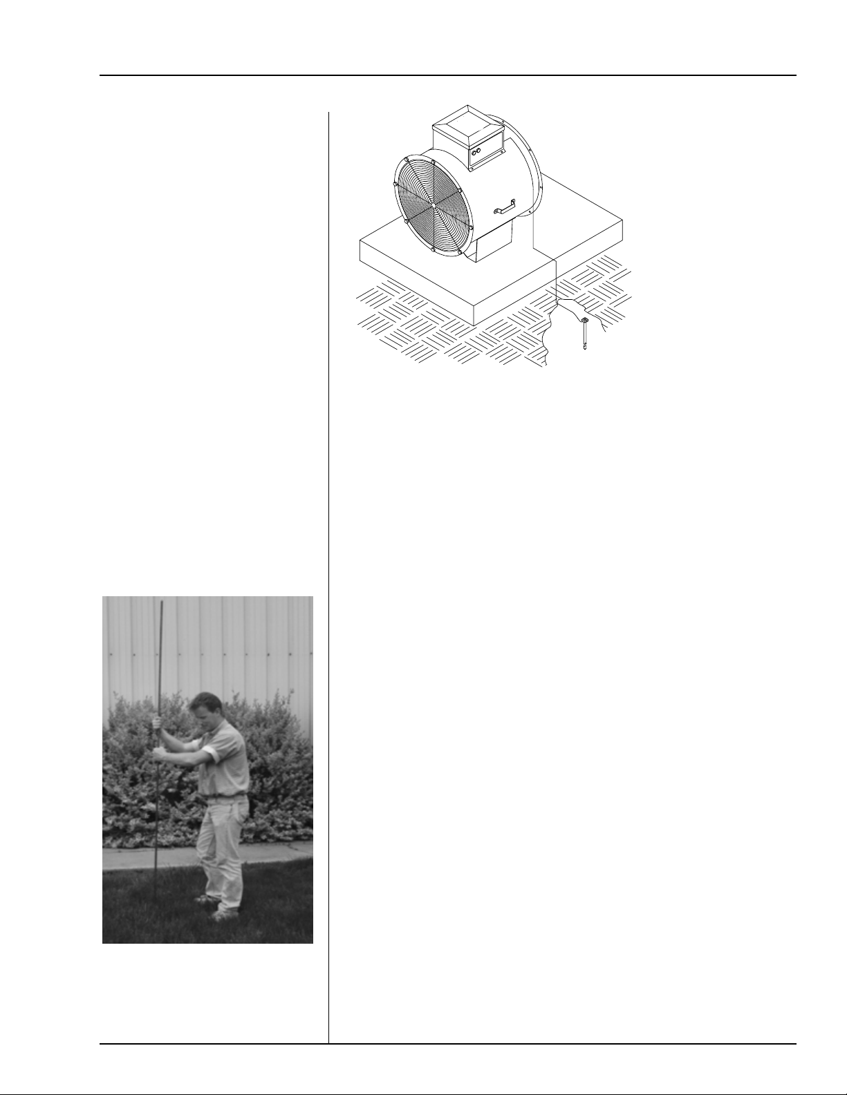
Figure 4: Use a #6 or approved
size bare copper ground wire.
Install a 5/8" diameter 8' long
copper-clad ground rod, 2'
away from the foundation and
1' below the surface of the
ground or in accordance with
local requirements.
Dig a hole large enough to hold 1
or 2 gallons of water. Work the
ground rod into the earth until it is
completely in the ground.
It is very important that a Ma-
chine To Earth Ground Rod be
installed at the fan. The ground
rod needs to be as close to the fan
as possible, but no more than 8
feet away. The ground rod should
be connected to the fan control
panel with at least a #6 solid, bare,
copper ground wire. The ground-
ing rod located at the power pole
will not provide adequate ground-
ing for the fan. The proper
grounding will provide additional
safety if there is a short and will
ensure long life of all circuit
boards used on control circuits,
and the ignition system. The
ground rod must be in accordance
with local requirements.
10
Electric Heater
OPERATION
Start Up
1. Turn thermostat knob to its warmest position.
2. Set heater switches to ON position. Red light
should be lit.
3. Watch thermometer on thermostat housing.
When temperaturereaches desired level turn
thermostat knob slowly to the left until heater
lights go out.
Remember: Electric heaters normally give no more
than 5-15 degrees temperature rise.
4. Observe the heater as it runs through a few cycles
to make sure thermostat is set correctly.
Service
All Electric Heater Units are designed and built to with-
stand use in the most severe environments. Take time
out at least once a year to go over the whole unit and
make sure everything is in working order. Preventive
maintenance can save time and money if done on a regu-
lar basis.
1. Always disconnect and lock out the power be-
fore working on or around fan motor and elec-
trical components.
2. Malfunctioning electrical components should be
checked by a qualified electrician.
3. Heater elements should be cleaned yearly to
avoid excess dust and dirt build up. Excessive
build up on heater may cause heater to perform
poorly and reduce the life of the heater elements.
Troubleshooting Chart
Symptom
Heater will not start.
Heater runs for short period of
time and kicks out high limit
switch.
Poor performance
Possible Cause
Blown fuse or breaker in
disconnect switch
Blown fuse in fan control box
Defective wiring or loose
connection
Incorrect wire size
Heater high limit kicked out
Defective thermostat
Thermostat not adjusted
Lack of airflow through heater
Defective high limit switch
Defective element
Low line voltage at the installation.
Power failure.
Dirt build up on element
Defective magnetic contactor
Remedy
Replace fuses or reset breakers.
Replace fuse.
Follow wiring diagram and tighten
any loose connections.
See wire size charts for proper
wire size and change if needed.
Check manual reset. Push in to
reset.
Replace thermostat.
Adjust thermostat settings.
Check for problems with fan or
obstructions that may be blocking
airflow.
Replace high limit switch.
Replace element.
Call power company after making
sure wire size is correct.
Clean element.
Replace contactor.