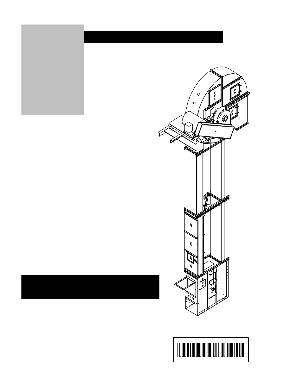
SERIES 2 BUCKET ELEVATOR ASSEMBLY MANUAL
Rev. 3 6/4/01 9
Receiving Inspection
Carefully inspect the shipment for damage as soon as it is received. Verify that the quantity of parts or
packages actually received corresponds to the quantity shown on the packing slip. Any discrepancies should be
clarified immediately. One or more cartons containing the fasteners required for assembly are included with the
shipment. Report any damage or shortage to the delivering carrier as soon as possible. The manufacturer’s
responsibility for damage to the equipment ends with acceptance by the delivering carrier. Refer to the bill of
lading. Save all paperwork and documentation furnished with any of the elevator components.
Pre-Installation Preparation
Our Bucket Elevators are designed to be vertically self-supporting when erected but must be supported or
guyed against wind loads.
NOTE: The elevator has not been designed to support other equipment such as cleaners, distributors
or spouting. Separate structures must be provided for any accessory equipment.
The manufacturer is the vendor of the elevator and certain of its optional accessories only and does not assume
responsibility for the installation recommendations contained within this manual. The installation
recommendations contained within this manual are for consideration only. The user or installer must consult a
civil or structural engineer regarding the design, construction and supervision of the entire installation, including
the elevator foundation and the guying cable and/or bracing system.
The MOST IMPORTANT preparations are retaining a licensed engineer to plan the installation and a qualified
millwright or contractor to erect the elevator and the accompanying equipment and structures.
Bucket Elevator Foundation
The bucket elevator foundation must be designed by a qualified civil engineer and installed by a qualified
contractor. Consideration should be given to live loads, dead loads, wind loads, and soil bearing loads.
Attention should also be given to ensure proper moisture run-off on the top of the base
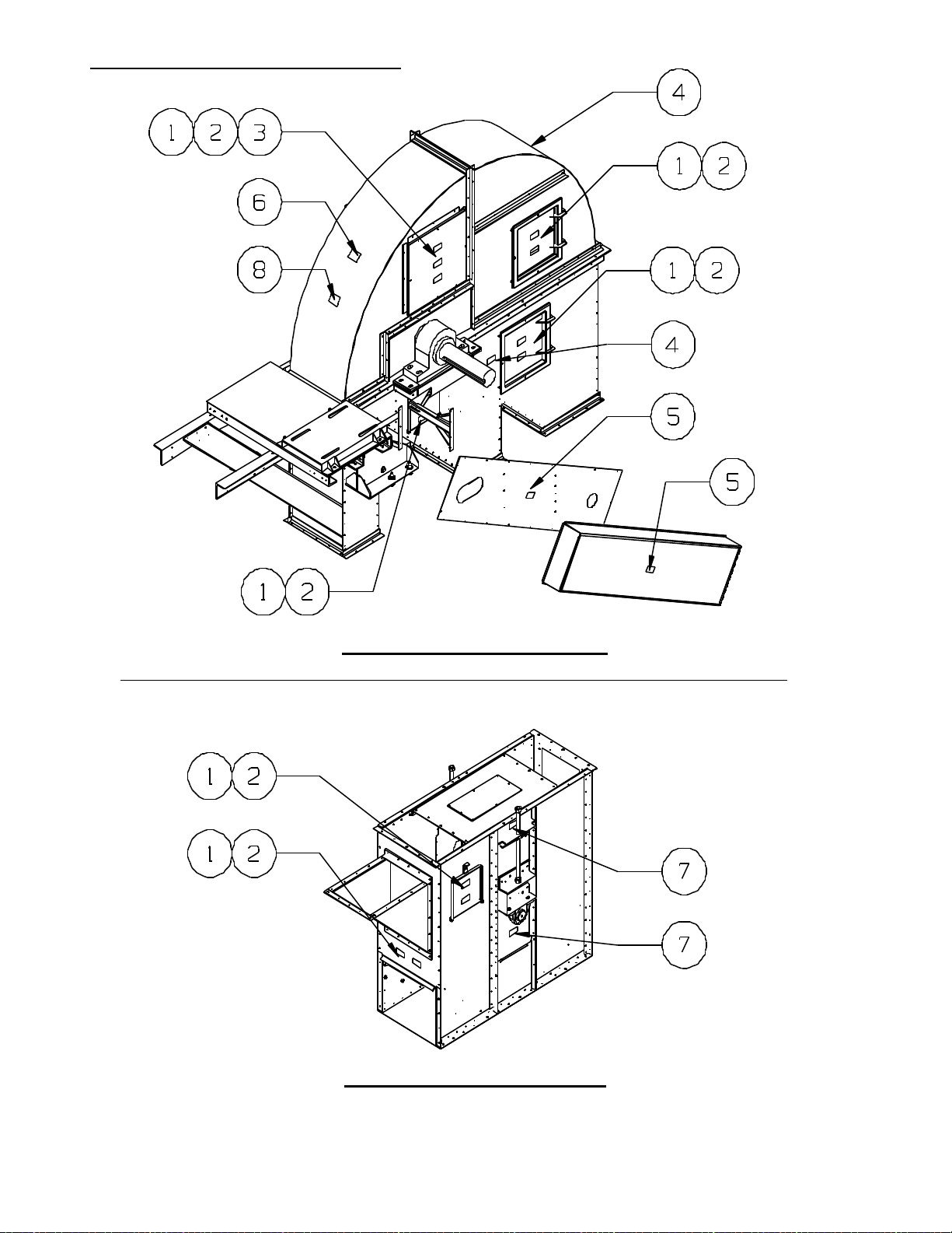
Boot Section
Prior to boot installation on the foundation, examine entire boot for any damage or loose hardware. Do not
attempt to install if parts are damaged.
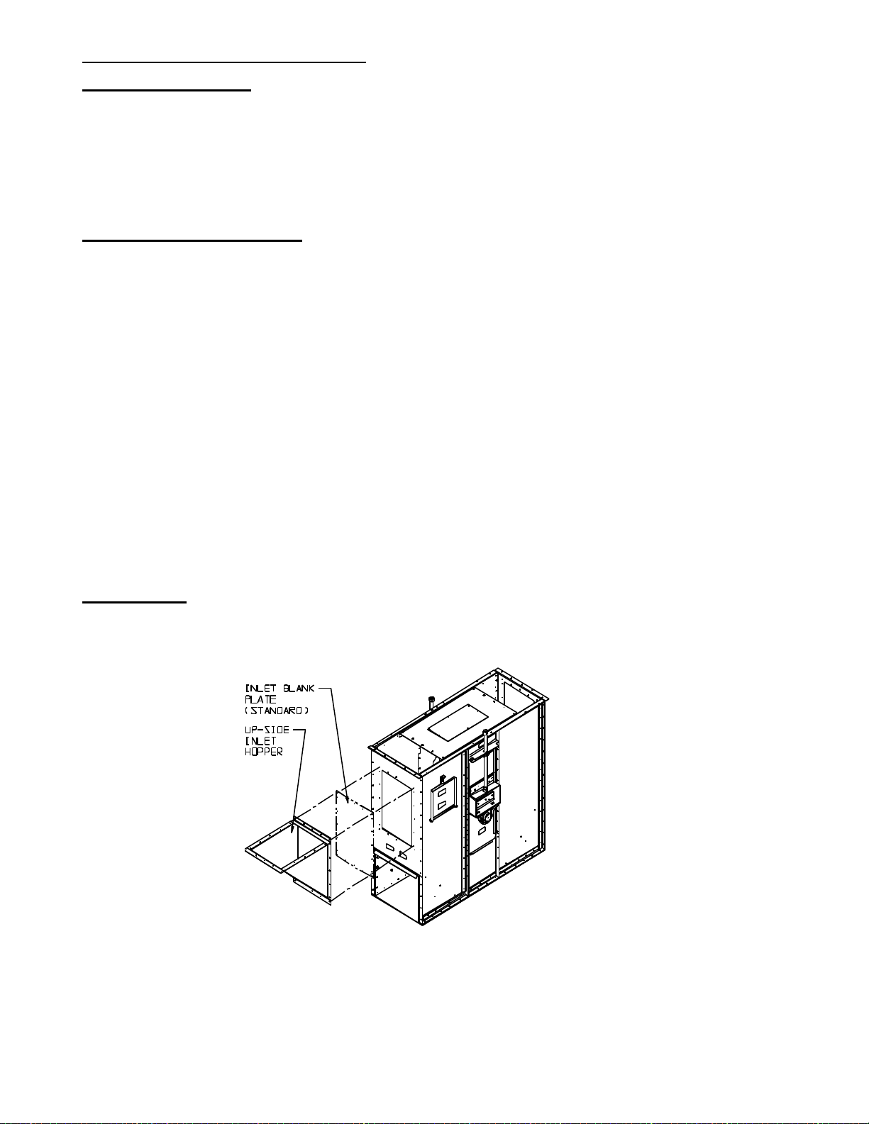
Boot sections are pre-assembled at the factory, however Boot Inlet Hoppers are typically shipped separately.
Take time now to identify the up and down side of the boot, as proper positioning is critical. The boot inlet
section can be installed either as an up-leg or a down-leg inlet. You will note that the up-leg inlet position is
approximately six (6”) inches higher than the down-leg side. By removing the nuts and blank-off plates from the
studs, the boot inlet hopper can be attached.