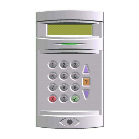
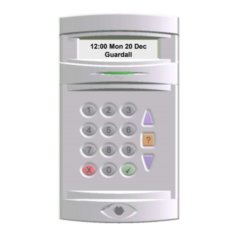
Guardall Windsor 500 Quick start guide

Windsor 500
Engineer Manual
Issue C

Windsor 500 Engineer Manual - Issue C
-
2
-
Contents
Contents.........................................................................................................2
System Overview...........................................................................................4
Software Differences............................................................................................................4
System Components............................................................................................................4
Main Control Unit..................................................................................................................5
Concentrators .......................................................................................................................5
User Interfaces......................................................................................................................5
Communicators.....................................................................................................................5
Output Devices......................................................................................................................6
Default Display...............................................................................................6
Windsor Menus..............................................................................................7
Menu Restrictions..........................................................................................8
Reset...............................................................................................................9
Unset...............................................................................................................9
Set.................................................................................................................10
Log................................................................................................................11
Test ...............................................................................................................11
Eng................................................................................................................12
Text ...............................................................................................................12
Text Library .........................................................................................................................13
Light..............................................................................................................14
PIN.................................................................................................................14
Bypass..........................................................................................................15
Chime............................................................................................................15
KP Off............................................................................................................15
Event Log .....................................................................................................16
Log Text...............................................................................................................................16
Users.............................................................................................................21
Time ..............................................................................................................21
Keys..............................................................................................................21
EvProg..........................................................................................................22
Remote..........................................................................................................22
Isolate ...........................................................................................................22
Edit................................................................................................................22

Windsor 500 Engineer Manual - Issue C
-
3
-
Copy..............................................................................................................22
Print...............................................................................................................23
Full........................................................................................................................................23
Changes...............................................................................................................................23
Text.......................................................................................................................................23
EvProg .................................................................................................................................23
Soak..............................................................................................................24
Cct ........................................................................................................................................24
Duration ...............................................................................................................................24
Limit .....................................................................................................................................24
Check............................................................................................................25
Conc.....................................................................................................................................25
Ccts ......................................................................................................................................25
Circuit Responses.............................................................................................................26
KPs.......................................................................................................................................26
Inputs ...................................................................................................................................27
Diagnostics..........................................................................................................................27
Battery Test.......................................................................................................................27
PSU Voltage......................................................................................................................27
Charge Current..................................................................................................................27
Demo.............................................................................................................28
Active Test....................................................................................................28
SmartCard ....................................................................................................29
Read .....................................................................................................................................29
Write.....................................................................................................................................29
Erase ....................................................................................................................................29
Appendix A - System Alarm Responses....................................................30
Tamper.................................................................................................................................30
Line Fault.............................................................................................................................30
Supply Voltage....................................................................................................................31
Duress..................................................................................................................................32
Appendix B - Text Library ...........................................................................33
Appendix C - Menu Layout..........................................................................34
Change History ............................................................................................37
Issue B .................................................................................................................................37
Issue C .................................................................................................................................37

Windsor 500 Engineer Manual - Issue C
-
4
-
System Overview
Windsor is a highly versatile control panel which can be fully programmed on site through a
keypad or remotely using a PC. Windsor can be programmed with up to 7 individual areas and
128 circuits. Each area can be programmed with it’s own sounder, strobe, communicator,
circuits, users and keypads.
There are 2 variants of Windsor;
•Windsor Commercial
•Windsor High Security
Windsor is also available in a number of languages.
The high security variant has a number of software options suitable for bank and other high
security installations which are not in the commercial variant. The hardware of both variants is
the same. The standard features contained in both variants is shown in the feature table.
Windsor Standard Features
Feature Maximum Capacity
Areas 7 + system
Concentrators 16 (external or internal types)
Circuits 128
Users 50
Light Zones 4
ISB PCBs 31
User interfaces 9
Event Log 300
Software Differences
There are a number of software differences between the Windsor commercial and high
security variants. The differences are;
•there are 2 versions of the event programmer; commercial and HS
•the HS has an ATM bypass feature
•the HS has a bank reset option
•the HS has more user authority types
System Overview System Components
The Windsor system comprises;
•the main control unit
•concentrators
•user interfaces
•communicators
•output devices
For full details of all system components refer to the Windsor Installation Manual.
1Windsor Mark 1 in a large case can be fitted with 5 ISB PCBs.

Windsor 500 Engineer Manual - Issue C
-
5
-
System Components Main Control Unit
The main control unit is housed in a metal case and contains a single PCB. The PCB
incorporates a 2 Amp power supply.
The main control unit can also have a number of expansion PCBs fitted on an internal serial
bus. This bus is referred to as the ISB. Up to 3 PCBs can be fitted on the ISB.
The ISB PCB types are;
•8 input concentrator, End of Line (EOL) or No End of Line (NEOL)
•SmartDial communicator
•8 output relay card (NO and NC contacts)
•8 output TX card
The functions of the ISB PCBs are fully programmable.
System Components Concentrators
Windsor can have up to 16 concentrators connected each with 8 individual alarm and tamper
inputs. The concentrators can be connected either on the ISB (maximum of 3) or the external
concentrator bus (maximum 16). Internal concentrators can have either EOL or NEOL inputs,
external concentrators can have EOL, NEOL or HS inputs. Any combination or concentrator
types2can be used all Windsor variants.
System Components User Interfaces
There are 3 types of Windsor user interface;
•LCD keypad
•Electronic keypoint
•INOVA Cardpoint
All user interfaces are connected to the panel on the user interface bus. Up to 9 user interfaces
can be connected to Windsor. At least one user interface must be an LCD keypad. All users
interfaces except user interface 0 are fully programmable.
System Components Communicators
Windsor supports a number of different communicator types;
•SmartDial
•Windsor Modem
•PAKNET
•STU
•Any third party communicator with parallel input triggers
•RS232 direct to PC
All communicators can be programmed for reporting alarms in various formats. Windsor
Modem and PAKNET communicators and RS232 direct can also be used for downloading.
2This includes Sovereign/Guardian, Vigil and Windsor concentrator types.

Windsor 500 Engineer Manual - Issue C
-
6
-
System Components Output Devices
Windsor can address up to 19 output devices. There are a number of different output device
types;
•ISB 8 output relay card (NO and NC contacts)
•ISB 8 output TX card
•8 output TX daughter board fitted to an external concentrator
•Plug on connector for STU (fitted to the main PCB as standard)
•2 output mains switching unit on the external concentrator bus
The function of all output devices is fully programmable.
Default Display
When Windsor is powered up the display will default to displaying the date and time. The
displayed format on each keypad can be modified by pressing the ↑button to change the top
line and the ↓button to change the bottom line.
Mon 02 Jan 95 The actual date will be different if PIN of the day is configured.
00:00
↑
W72200 V1.40 The top line shows the software order code and version number.
00:00
↑
Guardall The top line shows the programmed company name.
00:00
↑
Set:14 Set Disp will only be displayed if programmed for the keypad.
00:00 In the example shown areas 1 and 4 are currently set.
↑
Mon 02 Jan 95 The display is now back to the first format.
00:00
↓
Mon 02 Jan 95 The enter prompt will be displayed, even if the display is
Enter- defaulted to show the time, when a user is entering a PIN code.
The LCD backlighting will be turned on during the entry time, during a PIN entry and while a
user is logged on. It may also be turned on using the HELP button and turned off using the
QUIT button.

Windsor 500 Engineer Manual - Issue C
-
7
-
Windsor Menus
A Windsor menu consists of a list of options. Each option has a number and a prompt. As an
example when you enter a valid PIN code the display may look something like that shown
below.
2=Set 4=Test The actual number of options on display will depend on length of
5=Eng 6=Text.... the prompts but there will normally be 1 or 2 options on each line.
If there are more options than can be displayed on 2 lines there will be a series of dots ,“...”.
To see more options use the ↓button. If you already know the option number you require this
can be selected without the prompt being displayed provided the option is on the same page.
User options are split into two pages and there is an additional third page accessible only to
the engineer. You can move between pages by pressing the ↵button.
All possible Windsor user options are shown below. If the option you require is on the current
page it can be selected by entering the option number even if the option is not in the
displayed section of the page.
The Windsor user options are organised in 3 menu pages. Pages 1 and 2 are accessible by
users but page 3 is only accessible to the engineer.
0=Reset
1=Unset 1=Chime 1=Edit
2=Set 2=KP Off 2=Copy
3=Log 3=Event Log 3=Print
4=Test 4=User 4=Soak
5=Eng 5=Time 5=Check
6=Text 6=Keys 6=Demo
7=Light 7=Evprog 7=Active Test
8=PIN 8=Remote ↵=Next Page
9=Bypass 9=Isolate
↵=Next Page ↵=Next Page
User Page 1 User Page 2 User Page 3
(engineer only)

Windsor 500 Engineer Manual - Issue C
-
8
-
Menu Restrictions
All of the options on a page are not normally available at the same time. There are many
reasons why an option is not available. If you think an option should be available but the
prompt is not on display then press the corresponding button and Windsor will display an
appropriate message.
For example if no area is set and you select unset Windsor will prompt with the reason the
unset option is not available.
Not Available This indicates that there is no set area available to the user on
No Set Area this keypad.
The following table shows all no available reasons which can be displayed by Windsor.
Not Available Message Where Used
No Authority User tries to select an option which is not allowed with their
programmed authority level.
No Set Area User selects unset when all areas which can be unset from the
keypad are already unset.
Timer Control On User attempts to unset an area outside the event programmer
open/close time window or the vault timer is on for the area
(Windsor HS only).
No Unset Area User selects set when all areas which can be set from the keypad
are already set.
Set Area User attempts to access the log or test when an area is set.
Test in Progress User attempts to set an area which is being tested (on another
keypad).
System Not Unset User attempts to access an option which is only available when the
system is unset, for example the event log.
Unset Area User attempts to unset an unset area.
Key Not Used The key (button) which has been pressed is never used in the
current menu.
Printer Busy User attempts to print and the serial port is busy (printer or comm
port).
Already Tested User selects a test option which has been completely tested.
Not Programmed The option selected is no programmed or not programmed for the
current keypad.
Keypad Busy User attempts to turn off a keypad which is being used.
Not Applicable User attempts, for example, to reset when there are no alarms
logged.
Option in Use User selects test and another user is testing or user selects the
event programmer and another user is programming the event
programmer.
Log Empty User selects Log display when there are no events logged (3=Log
will not be on display)
At Bypass Limit User attempts to bypass a circuit when the number of bypassed
circuits is at the programmed bypass limit.
Call Engineer User attempts to set when an engineer reset is required.
Night Mode On User attempts to access Light zone test when the zone is in night
mode.
In the following sections each of the user options are explained together with the program
options associated with each user option. For full details of all edit options refer to the Windsor
Programming Manual.

Windsor 500 Engineer Manual - Issue C
-
9
-
User page 1 Reset
The reset option will only be on display if an alarm has occurred. This can be either an alarm
when Windsor was set or when unset. The reset menu option will only be displayed if Windsor
is unset and only if the user has chosen not to unset after the alarm log has been displayed.
The reset menu option will also be on display if the user is unable to reset after the alarm log
has been displayed.
There are a number of configuration options associated with reset. The area and system reset
options are located on page 2 of the edit menus. In addition a circuit may be configured as a
reset type (see Circuit edit).
Not all users have the authority to reset (see User edit). Windsor may also be configured for
reset from a PC using the GuardStation software (see Eng Comm edit).
User page 1 Unset
The unset option will only be displayed if one or more of the areas that the user is authorised to
unset on a keypad is set. It will never be displayed if the set area(s) are configured to unset
automatically when an authorised user logs on (see Keypad edit). Unsetting will be automatic
if the area(s) is unsetting when the user logs on or if the area(s) are configured for
LogOn/Unset. If unsetting is through an entry/exit route and the EnEx circuit is programmed for
system then only the authorised areas will unset when a user logs on.
Windsor may also be unset by a Key circuit (see Circuit edit) or by a timer (see EvProg edit).
One area may be configured as a Common Area which will be automatically unset if any other
area is unset.
Not all users have the authority to unset (see Users edit). Windsor may also be configured for
unset from a PC using the GuardStation software (see Eng Comm edit).
Windsor can be programmed for unsetting multiple areas in one operation (Group Unset).
When a user selects unset and group unset is programmed then the unset options will include
an additional option, 8=Group Unset. If Group Set is on and there is more than 1 set area the
system option will also be displayed.
0=System
1=Area 1
2=Area 2
3=Area 3
4=Area 4
5=Area 5
6=Area 6
7=Area 7
8=Group Unset
The above example is for a system programmed for 7 areas. In a smaller system the group
unset option will still be option 8. If group unset is selected Windsor will show the areas that
are unset and the areas which are available for unsetting;
Unset:12 Areas already unset
Set:34567 Areas available to unset
Any combination of areas can be selected. To start group unsetting press the ↵button.

Windsor 500 Engineer Manual - Issue C
-
10
-
User page 1 Set
The set option will only be displayed if one or more of the areas that the user is authorised to
set on the keypad is unset. Windsor may also be set by a Key circuit (see Circuit edit) or by a
timer (see EvProg edit). One area may be configured as a Common Area which will be
automatically set when all other areas are set. When a user requests setting the set mode will
depend on the mode programmed for the setting area(s) (see Keypad edit). Setting can be
completed by;
•a timer at the end of the programmed exit time
•by closing the final exit point (EnEx circuit type)
•by pressing the push button (PB type) after closing the final exit point
Not all users have the authority to set (see Users edit). Windsor can also be set from a PC
using the GuardStation software (see Eng Comm edit).
Windsor will auto set at power up if LK4 on the main PCB is fitted and the panel was set
when the power was removed. There is 1 minute delay when power is restored to allow the
sensors to stabilise before the setting process starts. See also battery test prior to setting.
Windsor can be programmed for setting multiple areas in one operation (Group Set). If all of
the setting areas in the group are programmed for instant setting the group will be set instantly.
If one or more area in the group is programmed for non-instant setting then the programmed
system set mode will be used. When a user selects set and group set is programmed then the
set options will include an additional option, 8=Group Set;
0=System
1=Area 1
2=Area 2
3=Area 3
4=Area 4
5=Area 5
6=Area 6
7=Area 7
8=Group Set
The above example is for a system programmed for 7 areas. In a smaller system the group set
option will still be option 8. If group set is selected Windsor will show the areas that are set and
the areas which are available for setting;
Set:12 Areas already set
Unset:34567 Areas available to set
Any combination of areas can be selected. To start group setting press the ↵button.
The number of areas which can be set on any keypad can be limited by programming areas as
Off or as Unset only (see Edit, KP Set mode). If the system option is programmed for a
keypad and one or more areas are programmed as Off or Unset only then, when a user
selects setting, only those areas which have been individually programmed with a set mode will
be set. This operation is identical to group setting and the message Group Set will be displayed
when more than 1 area is set at the same time.
When setting using a final exit circuit the EnEx circuit can be programmed to only operate
when the system is being set. This allows, for example, the main door of a multiple area
system to open when the system is not fully set without starting an entry timer for set areas.

Windsor 500 Engineer Manual - Issue C
-
11
-
User page 1 Log
The alarm log menu option will normally only be on display if the user is unable to reset after
an alarm has occurred. A user can choose not to reset a log when the log is automatically
displayed and then use the log menu option to print the alarm events. Windsor has an alarm
log for each area which stores up to 10 events. Windsor also has an event log which stores up
to 300 events (see Event log option). When the log is displayed in can be viewed in two
formats.
Alarm Event description
PIR in Hall Circuit description
Press the HELP button to display the alternative format which shows the time and circuit
number.
HH:MM Cct001
Time and circuit number
Alarm Event description
You can set the display mode you prefer or use the HELP button to switch between display
modes as you scroll through the logged events. Windsor will normally scroll through the events
automatically. However, you can use the ↑and ↓buttons to step through the events manually.
Automatic scrolling can be enabled again by pressing the ↵button.
Not all users have the authority to access the log (see Users edit).
User page 1 Test
Users with Manager, ordinary, Set/unset and set only authority are allowed to test Windsor.
Each area of Windsor can be tested separately and within each area different types of circuit
can be tested in isolation. This minimises the loss of protection during the test time. The
sounders for each area and the communicator(s) may also be tested. The communicator test
option is only available if the system is being tested.
The circuit test options are;
Circuit Test Option Circuit Types Tested
PA PA and PA-Snd only
24 Hour Fire and 24Hr circuits with detector attribute off
Detector 24hr, NA and ER circuits with detector attribute on
Walk All other types of circuit except Exc-T3and Exc-D
The overall test time is limited to 1 hour. However, within the overall test time, the PA and 24
hour tests are each limited to 20 minutes. A warning will be given 5 minutes before the end of
the test. If the user does not end the test by the end of the test time then Windsor will exit test
mode automatically. Any fire sensor still in alarm will give a normal alarm response. 24 hour
sensors still in alarm will be temporarily bypassed. A warning will be displayed if any PA sensor
is still in alarm.
Windsor records all activations from sensors during the unset period. If walk test is selected a
user can choose to test all circuits in the area (select Manual) or test only those circuits which
have not activated during the unset period (select Auto). When the area is tested all recorded
unset activations are cleared. If a user starts a test then all circuits must be tested. Any circuit
which is not tested will be logged in the event log.
3Exc-T circuits can be tested by using the lights test option.

Windsor 500 Engineer Manual - Issue C
-
12
-
An engineer can program 24Hr, NA and ER circuits as detectors. Circuits programmed as
detectors can be tested manually or automatically at a programmed time (see Detector edit).
This is only useful if you are using sensors which have a test input (such as a vibration
sensor). The test input should be connected to a concentrator output programmed for detector
test (see Conc edit).
If the communicator test is selected then all telephone numbers configured for test will be
tested (see Comms edit).
User page 1 Eng
When Windsor is powered up an engineer can log on directly and has up to 8 hours working
time on the system. At all other times the engineer can only log on after a user PIN code is
entered and the Eng option is selected and the engineer test time is limited to 1 hour. The
engineer will always be given a warning 5 minute before the end of the working time. The
working time can be extended by 1 hour by re-entering the engineer PIN code during the
warning period. Windsor can be programmed to allow an engineer log on without first entering
a user PIN code.
Once logged on an engineer can log on and off any keypad during his working time. If an
engineer selects the Eng option then the engineer will be logged off the system. Engineer log
on and log off times are stored in the event log.
User page 1 Text
Windsor can be programmed with text descriptors for circuits, users, areas, bypass group and
the company name. Circuit descriptors may be copied by the engineer.
Descriptor Default Auth. Required Where Used
Company Name Guardall Engineer only Keypad top line when no user logged on
(option)
Users User nn Eng/Man/Ord Event log, Programming Authority and PINs,
setting (with keyholders)
Circuits Cct nn Eng/Man/Ord Event log, Programming ccts, Active testing,
Bypassing, Check mode, multiple alarm
warnings, setting warnings, testing (untested
ccts)
Areas Area n Eng/Man/Ord Event log, Detector test reports, area menus
(set etc.), programming users.
Bypass Groups Group n Eng/Man/Ord Event log, Programming users/ccts,
bypassing.
The text menu can be accessed either from option 6 on user page 1 or from option 0 on edit
page 2.
1=Circuit There are 5 text menu options for the engineer. Option 5 is not
2=User displayed for a manager or ordinary user.
3=Area
4=Group
5=Co.Name
As an example to edit a circuit description select option 1 and then enter the circuit number.
Cct Number 1 The item being edited
Cct 1 The current description

Windsor 500 Engineer Manual - Issue C
-
13
-
All text descriptors can be up to 12 characters long and may contain any of the following
characters;
“ABCDEFGHIJKLMNOPQRSTUVWXYZabcdefghijklmnopqrstuvwxyz .-
/#%^&*@<>0123456789”
When you edit a text descriptor the first letter will be flashing. You can either use the ↑and ↓
buttons to select the required character or use the one of the numeric keys to quickly access a
particular character.
Use the ↵button to move to the next character position. Press QUIT to save the descriptor
and exit. To clear all characters to the right of the cursor press 0.
Text descriptors may also be programmed on a PC using the GuardStation software and
downloaded to Windsor.
Text Text Library
Windsor has a library of words which can be used when editing text descriptors. To access the
text library press the HELP button when editing a text descriptor.
Text Number-__
The text library reference number for the word.
When a text number is entered Windsor will display the word and prompt the user to accept.
Accounts
The selected word.
↵=Confirm
If the word is accepted it will be copied to the current cursor position of the descriptor being
edited. Pressing any other button will return the display to the Text Number entry prompt.
The contents of the text library are listed in appendix B.
A
M
Z
a
m
z
1
9.
Clear

Windsor 500 Engineer Manual - Issue C
-
14
-
User page 1 Light
Windsor can be programmed with up to 4 lights zones. All of the light zone options are
accessible to the engineer. A manager or ordinary user can program all light options except the
light output channel.
The light zone options can be accessed either by selecting option 8 from page 2 of the edit
menus or option 7 from page 1 of the user menus. A manager or ordinary user can program all
light options except the outputs.
1=Operations There are 6 light zone user menu options.
2=On Time
3=Off Time
4=Dusk Time
5=Manual
6=Test
For a full explanation of the lights options see the Windsor programming manual.
User page 1 PIN
A user on the Windsor system is identified by either a PIN code (4, 5 or 6 digits), a SmartKey
or a Cardpoint card. A total of 50 users may be programmed. User 1 is the engineer user and
the engineer PIN code cannot be changed to a key or a card. User 2 has a fixed authority of
manager for all areas and the user 2 PIN cannot be changed to a card.
All users can change their own PIN code and users with manager authority can change any
users PIN code. The engineer can only change his PIN code if PIN of the day is not
programmed (see Defaults edit). A user can only change code to a card on a Cardpoint. All
PIN code changes, including changes to Cardpoint cards are recorded in the Windsor event
log.

Windsor 500 Engineer Manual - Issue C
-
15
-
User page 1 Bypass
Windsor can be programmed to allow circuits to be bypassed. Each circuit can be
programmed in any combination of 6 bypass groups and users can be programmed with
authority over any combination of bypass groups. Not all users have the authority to bypass
(see Users edit). Windsor may also be configured for bypass from a PC using the
GuardStation software (see Eng Comm edit).
When a circuit is bypassed the circuit alarm response is ignored. The tamper response
remains unaffected (see also the Isolate option). Windsor will normally remove the circuit
bypass when the circuit is unset unless the circuit has a 24 hour response and the circuit is still
in alarm. A circuit can normally only be bypassed if the it is unset. However, during a bank
reset circuits which are set and are in alarm will be bypassed (see Reset edit). When an area
is being set Windsor will display all bypassed circuit numbers.
Manager, engineer and ATM users can bypass all circuits in a group in one operation (see
ATM edit).
Windsor can be programmed with a bypass limit. This restricts the number of circuits in the
system that can be programmed at any one time. This limit also applies to group bypass. If a
bypass group contains more circuits that the bypass limit then only circuits up to the bypass
limit will be bypassed. All bypass operations are logged in the event log.
Windsor can be programmed to indicate area bypass on a TX output. The Bypass TX output
will be on if any circuit in the area is bypassed.
In addition to bypass Windsor can be programmed to ignore a circuit alarm response in other
ways (see EvProg shunt and Circuit shunt, bypass and temp bypass for more details).
User page 2 Chime
Windsor can be programmed to give a chime from NA, ER, EnEx, PB and Exc-T circuit types
when in the unset mode. Not all users have the authority to program circuit chime (see Users
edit).
When selected a chime tone will sound on the audio output and, if the keypad(s) is
programmed for Bleeper operation (see Keypad edit), all keypad bleepers in the circuit area.
User page 2 KP Off
A Windsor keypad can be disabled from another keypad by a manager or engineer user. A
keypad which is disabled in this way will be remained off until turned back on. When a keypad
is turned off the message “Out of Service” is displayed on the LCD.

Windsor 500 Engineer Manual - Issue C
-
16
-
User page 2 Event Log
Windsor can store up to 300 events in the event log. The event log may be displayed or printed
in full or in filtered form.
1=Circuit There are 4 event log filter options.
2=User
3=Keypad
4=Date
All events stored in the event log are numbered 0 - 65535. When the log is printed or uploaded
to a host the event number is used. The event number is never displayed. The event number
will be the same even if the event is printed as part of a filtered log. The event number will only
be reset if more than 65535 events have been recorded.
Event Log Log Text
Log messages are constructed using the event time, the event type and the additional
information specified by the event type. If a text description has been programmed it will be
used in the printed log. When the log is displayed abbreviations are used. The displayed log
format is;
Bypassed the event type
PIR in Hall the circuit description
The event time and circuit number may be displayed in place of the normal top line information
by pressing the HELP button.
12:00 UsNNCctXXX the event time and additional data
Bypassed the event type
You can set the display mode you prefer or use the HELP button to switch between display
modes as you scroll through the logged events. Windsor will normally scroll through the events
automatically. However, you can use the ↑and ↓buttons to step through the events manually.
Automatic scrolling can be enabled again by pressing the ↵button.
In the table below all messages logged by Windsor are shown. Some message types are
stored in both the alarm and event logs and some are stored in the event log only.

Windsor 500 Engineer Manual - Issue C
-
17
-
Event log and Area log messages
Log Text Additional Data Display Text Event Description
Alarm Circuit nnn Cctnnn A Circuit alarm
Auto Check Fail Circuit nnn Cctnnn A Circuit has failed to
activate during the auto
check period.
AV60 Tamper NONE NONE Tamper on an AV60
input channel.
Battery Low NONE NONE The battery has reached
the low volts threshold
(after a mains fail)
Conc. Tamper n n Concentrator Tamper
Entry Alarm Area nAnThe area is not unset
before the end of the
entry warning period
EVP Shunt Fault (HS only) Circuit nnn Cctnnn The circuit is in alarm
when the event
programmer removes the
shunt
Fire Circuit nnn Cctnnn A fire type circuit alarm
Panel Tamper NONE NONE Panel case or off the
wall tamper
Personal Attack Circuit nnn Cctnnn A PA type circuit alarm
Rmt.Auth Fail NONE NONE Repeated attempt to log
on by a remote host
Sounder Tamper NONE NONE External sounder tamper
Tamper Circuit nnn Cctnnn A circuit tamper
Tamper Keypad nKPn A keypad tamper
Event log only messages
230v Failed NONE NONE Mains supply failed
230v Restored NONE NONE Mains supply restored
Active Cct.Test Circuit nnn Cctnnn User selected active
circuit test
Alarm (master shunt) Circuit nnn Cctnnn Master shunt type circuit
alarms
Alarm Abort User nn, Keypad m Usnn, KPmAlarm abort signal
transmitted.
All Ccts Tested User nn, n Usnn, KPmAll circuit(s) tested,
where n=1 for PA; n=2
for Walk, n=3 for 24hr
and n=4 for detector.
Audio Untested User nn, Area mUsnn, AmUser exits test without
testing the audio output
Auto Set User nn, Area mUsnn, AmEvent programmer
automatically set area
Auto Set & Fault User nn, Area mUsnn, AmEvent programmer
automatically set area
with circuit(s) in alarm
Auto Unset User nn, Area mUsnn, AmEvent programmer
automatically unset area
AV60 Mute NONE NONE CS connection to AV60
has requested a
sounders mute.
Aux Circuit nnn Cctnnn Auxiliary type circuit
alarms

Windsor 500 Engineer Manual - Issue C
-
18
-
Event log and Area log messages
Log Text Additional Data Display Text Event Description
Bat.Monitor Fail NONE NONE Battery voltage is low or
not present during a
battery test
Beam Active Circuit nnn Cctnnn Circuit programmed as
one of a beam pair is in
alarm
Bypass User nn, Circuit mmm Usnn Cctmmm Circuit bypassed
Changed Holiday User nn, Keypad m Usnn, KPmEvent programmer
holiday date changed
Changed PIN Code User nn, Keypad mUsnn, KPmUser changes own PIN
Changed PIN for User nn, User mm Usnn, Usmm Manager or GCM user
changes PIN for another
user
Changed Schedule User nn, day Usnn, day Event programmer re-
programmed
Changed Time User nn, Keypad mUsnn, KPmTime modified, old time
and new time are logged
Clear (master shunt) Circuit nnn Cctnnn Master shunt type circuit
clears
Comm Acknowledge n nCentral station
acknowledges alarm
report
Comm Fail n nCentral station fails to
acknowledges alarm
report
Comm Test User nn, Keypad m Usnn, KPmUser or Windsor tested
the communicator(s)
Comm Untested User nn, nUsnn, nUser exits test without
testing the
communicator
Det Test Fail User nn, Keypad mUsnn, KPm
Circuit(s) programmed as
detector failed to alarm
during a manual or
automatic detector test
Dorm Confirmed Circuit nnn Cctnnn Second dormitory circuit
alarms
Dorm Initiated Circuit nnn Cctnnn First dormitory circuit
alarms
Duress Alarm User nn, Keypad m
Usnn, KPmUser enters a duress
code
EAC Log On Circuit nnn Cctnnn EAC Log on circuit type
alarms
Engineer Reset Circuit nnn Cctnnn Engineer reset type
circuit alarms
Entry Started Circuit nnn Cctnnn Entry circuit opens
Failed Auto Set User nn, Area mUsnn, AmEvent programmer failed
to auto set due to circuits
in alarm
First PIN User nn, Keypad mUsnn, KPmUser entered PIN on
Dual PIN keypad
GCM Access User 00 Usnn A GCM user has logged
on remotely.
Isolate User nn, Circuit mmm Usnn Cctmmm Circuit isolated by user

Windsor 500 Engineer Manual - Issue C
-
19
-
Event log and Area log messages
Log Text Additional Data Display Text Event Description
Isolate (conc) User nn, mUsnn, mConcentrator isolated by
user
Key List Error User nn, Keypad m Usnn, KPmUser sets after
confirming keyholder
names are wrong
Key Set Req. Circuit nnn Cctnnn Key type circuit alarms
Key Unset Req. Circuit nnn Cctnnn Key type circuit clears
Late Working Off User nn, day Usnn, day Late working is turned off
for the day
Late Working On User nn, day Usnn, day Late working is turned on
for the day
Line Block NONE NONE SmartDial has reported a
line blocked condition
Line Fault 1 - 50 volts not present
2 - Line block test failure
3 - No acknowledge from
central station
NONE Communicator has
reported a line fault
Lockout Keypad nKPnIncorrect PIN attempt
limit reached on the
keypad
Logged Off User nn, Keypad mUsnn, KPmUser logged off keypad
Logged On User nn, Keypad mUsnn, KPmUser logged on keypad
Multiple Alarm Circuit nnn Cctnnn Circuit has alarmed up to
the multiple alarm limit
New Access User User nn, Keypad m Usnn, KPmA card on an INOVA
CardPoint has been
programmed as an
alarm card user
Normal (conc) User nn, mUsnn, mIsolate removed from a
concentrator
Normal (removed bypass) User nn, Circuit mmm Usnn Cctmmm Bypass removed from a
circuit
Normal (removed isolate) User nn, Circuit mmm Usnn Cctmmm Isolate removed from a
circuit
PIN Code Clash User nn, User mm Usnn, Usmm User has chosen a new
PIN code which is the
same as another user
Power Fail NONE NONE Supply voltage has
fallen to the power fail
threshold
Pre-Warning Circuit nnn Cctnnn A circuit has been
alarmed during the entry
period
Reprogrammed User nn, Keypad m
Usnn, KPmA configuration option(s)
has been changed
Reset User nn, Area mUsnn, Usnn An areas has been reset
Reset Fire Alarm User nn, Area mUsnn, AmA fire type circuit has
been reset
Restored PINs User nn, Keypad mUsnn, KPmAll PINs have been
restored to default
Restore Circuit nnn Cctnnn A Circuit alarm has
restored.
Set User nn, Area mUsnn AmArea has been set by a
user

Windsor 500 Engineer Manual - Issue C
-
20
-
Event log and Area log messages
Log Text Additional Data Display Text Event Description
Shunt Off Circuit nnn Cctnnn A master shunt circuit or
the event programmer
schedule has removed
the shunt from a circuit
Shunt On Circuit nnn Cctnnn A master shunt circuit or
the event programmer
schedule has shunted a
circuit
Soak Alarm Circuit nnn Cctnnn A circuit on soak test has
alarmed
Soak Failed Circuit nnn Cctnnn At the end of the soak
period any circuit which
has alarmed is logged as
fail
Soak Off Circuit nnn Cctnnn A circuit has been taken
off soak
Soak On Circuit nnn Cctnnn A circuit has been put on
soak
Sounder Untested User nn, Area mUsnn, AmUser exits test without
testing the sounder
output
Strobe Untested User nn, Area mUsnn, AmUser exits test without
testing the strobe output
Tech Rst Keypad nKPnA technostore code has
been entered.
Temp Bypass Circuit nnn Cctnnn A circuit has been
temporarily (until clear)
bypassed
UI Fire Alarm Keypad nKPnThe fire buttons on the
keypad have been
pressed
UI Medical Alarm Keypad nKPnThe medical buttons on
the keypad have been
pressed
UI PA Alarm Keypad nKPnThe PA buttons on the
keypad have been
pressed
Unset User nn, Area mUsnn AmUser has unset the area
Untested User nn, Circuit mUsnn,
Cctmmm User exits test without
testing all circuits
Verify Alm Area nAnA verified alarm has
occurred
Other manuals for Windsor 500
2
Table of contents
Other Guardall Security System manuals