Features
ÿ8 zones, all programmable for Security,
Fire, 24H Fire, PTS or keyswitch
applications
ÿPA input
ÿTamper input
ÿOutputs for Bell and Strobe
ÿ4 Access level Codes, User 1, User 2,
Engineer and Duress, all programmable
ÿ3 fully selectable part set programs
ÿChime on any zone
ÿ8 event memory
ÿProgrammable timers including bell cut off
ÿWalk Test facilities
ÿQuick set feature
ÿRemote keypad with on board PA and
illuminated keys standard for Accenta
panels and Optional for Optima panels
ÿOption for connection of Lighting
controllers
ÿOptions to connect up to four remote
keypads / Lighting controllers
ÿNVM for protection of engineer programme
ÿ6 digital outputs for a wire-in digital
communicator, Red Care STU or dialler
(Not applicable for Optima compact G3
panel)
ÿService warning indicator, programmable
between 100 and 800 set and unset events
ÿBattery capacity of up to :
2.1Ah in Accenta/Optima G3 mini enclosure
7Ah in Accenta/Optima G3 enclosure
ÿOptima G3 and Optima G3 mini are supplied
with built in keypad
24PI175 issue 1_6/01
Engineering information Accenta/Optima G3 Intruder system
Features
Contents
Features -------------------2
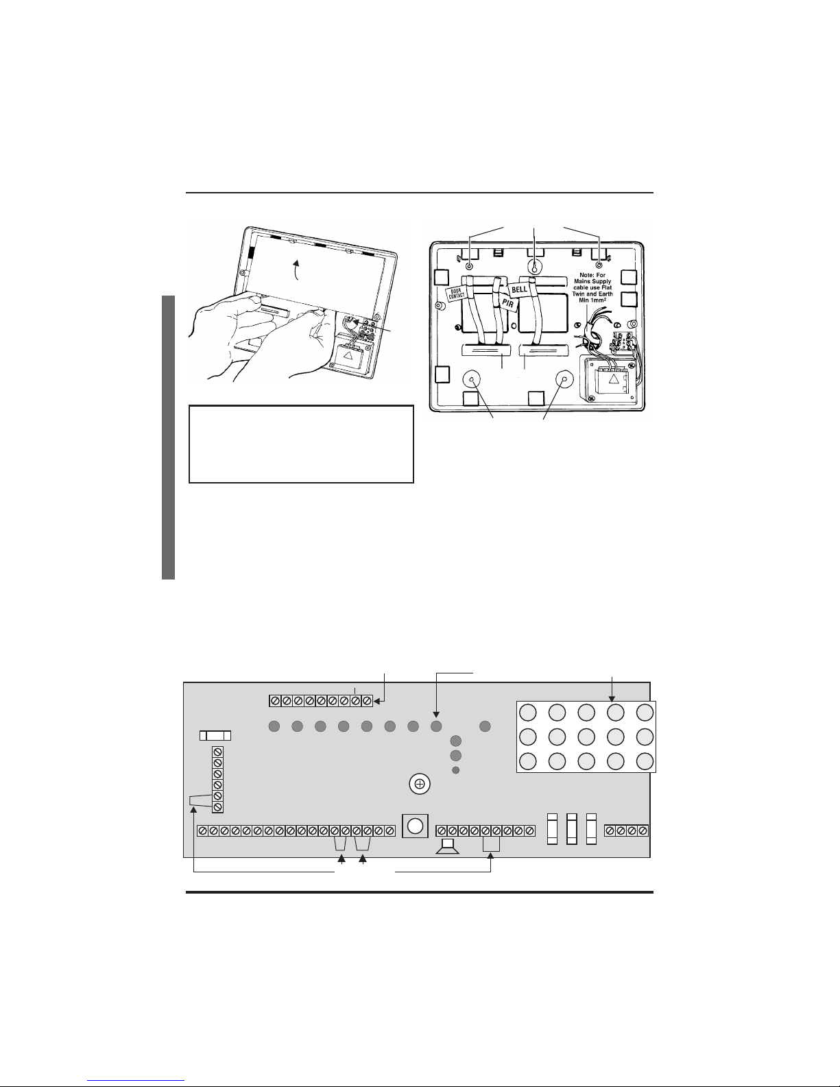
Installation Design --------------3
Fixing --------------------3
Wiring the system --------------5
Tamper network ---------------5
Connect Remote Keypads / Lighting controllers 5
Security zones ----------------5
Push to set zone ---------------6
Remote keyswitch zone -----------6
Fire zone ------------------6
PA circuit ------------------6
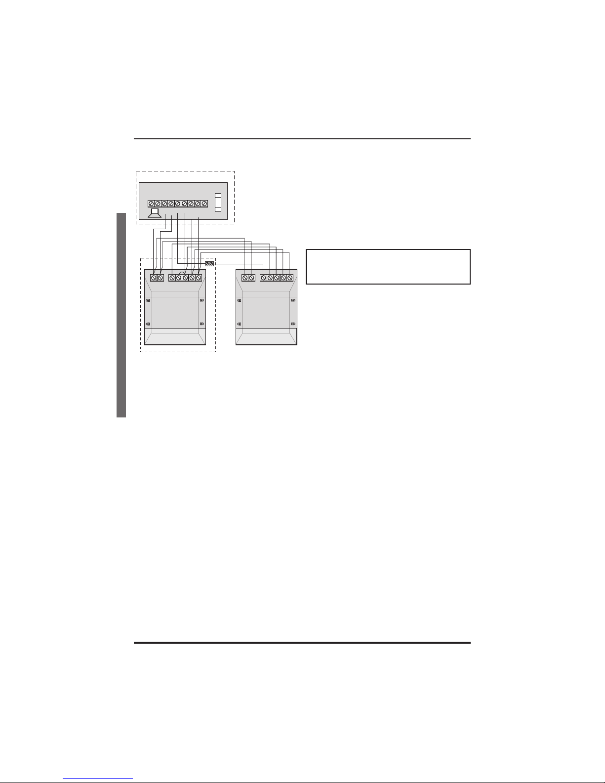
Extension speaker --------------7
Bell Output (External sounder) --------7
13V Supply output --------------8
Set ---------------------8
Remote signalling Input and Outputs -----8
Filtering of Intruder alarms -----------9
Factory set condition -------------10
First Power up ----------------11
Mains Connection --------------11
Testing the system --------------12
Engineer program mode -----------12
To exit ---------------------12
System indications --------------12
To enter Engineer program mode -------12
To Exit Engineer program mode -------12
To reset panel to Factory set conditions ----12
Access Codes ----------------13
Programs ------------------14
Zone Function per Program----------14
Exit Modes program -------------14
Programs 1,2 and 3--------------15
Alarm and Walk tests ------------16
Communicator tests -------------17
‘Flag A’ Options ---------------17
‘Flag B’ options ---------------18
Viewing the event log ------------18
Zone Type ------------------19
Zone Attributes ---------------20
Bell and Service Timers -----------21
Re-arm and Anticode reset code -------22
Lighting controller --------------23
Faults --------------------24
Specification-----------------25
Servicing organisation Details --------27
Parts --------------------27
Quick Reference ---------------28
8
z
RKP
4
PART
SET
MEM
8
OUTPUT
6
REMOTE
SET
509