Guardian voip telephone Quick guide

7552 - 10th Street N.E. Calgary, Alberta, Canada T2E 8W1
Ph: 403.258.3100 \ email:info@guardiantelecom.com \ www.guardiantelecom.com
Industrial Communications Worldwide
VoIP Telephones
Setup & Configuration
P007402 Rev. B 120620 7/4/2012 2:36 PM

Guardian Telecom Inc. Setup & Configuration
VoIP Telephones
VoIP Setup & Configuration P007402 Rev. B
COPYRIGHT NOTICE:
© 2012, Guardian Telecom Inc., ALL RIGHTS RESERVED.
This manual and related materials are the copyrighted property of Guardian Telecom Inc. No part of this manual or related
materials may be reproduced or transmitted, in any form or by any means (except for internal use by licensed customers),
without prior express written permission of Guardian Telecom Inc.. This manual, and the products, software, firmware, and/or
hardware described in this manual are the property of Guardian Telecom Inc. provided under the terms of an agreement
between Guardian Telecom Inc. and the recipient of this manual, and their use is subject to that agreement and its terms.
DISCLAIMER: Except as expressly and specifically stated in a written agreement executed by Guardian Telecom Inc.,
Guardian Telecom Inc. makes no representation or warranty, express or implied, including any warranty or merchantability or
fitness for any purpose, with respect to this manual or the products, software, firmware, and/or hardware described herein, and
Guardian Telecom Inc. assumes no liability for damages or claims resulting from any use of this manual or such products,
software, firmware, and/or hardware. Guardian Telecom Inc. reserves the right to make changes, without notice, to this
manual and to any such product, software, firmware, and/or hardware.
OPEN SOURCE STATEMENT: Certain software components included in Guardian products are subject to the GNU General
Public License (GPL) and Lesser GNU General Public License (LGPL) “open source” or “free software” licenses. Some of this
Open Source Software may be owned by third parties. Open Source Software is not subject to the terms and conditions of the
Guardian COPYRIGHT NOTICE or software licenses. Your right to copy, modify, and distribute any Open Source Software is
determined by the terms of the GPL, LGPL, or third party, according to who licenses that software.
Software or firmware provided by Guardian that is unrelated to Open Source Software is copyrighted by Guardian, subject to
the terms of Guardian licenses, and may not be copied, modified, reverse-engineered, or otherwise altered without explicit
written permission from Guardian Telecom Inc.
TRADEMARK NOTICE: Guardian Telecom Inc. and the Guardian Telecom Inc. logos are trademarks of Guardian Telecom
Inc. Other product names, trademarks, and service marks may be the trademarks or registered trademarks of their respective
owners.
Toll-free 1-800-363-8010
Phone (403) 258-3100
Fax. (403) 253-4967
www.guardiantelecom.com
E-mail: [email protected]
Page 2

Guardian Telecom Inc. Setup & Configuration
VoIP Telephones
Page 3
IMPORTANT Installation Step
It is important to register this VoIP product with Guardian Telecom to ensure it has the
most current version of software and to receive notification of software updates.
Registering Your VoIP Product
Be sure to include “Guardian VoIP Registration” in the subject field of your email.
Include the following information:
Company Name of End User (Req'd)
Address of End User (Optional)
Device Model (Req'd)
Serial Number (Req'd)
Date of purchase (Req'd)
Name of Supplier (Req'd)
Prime Contact name and e-mail (Req'd)
Secondary Contact name and e-mail (Optional)
Phone Info: (Optional)
It is very important that we receive e-mail contact information of the person responsible
for maintaining the installed Guardian Equipment, in order to ensure optimum
performance of the device.
Contact information will remain confidential and will not be used for third-party
marketing purposes.

Guardian Telecom Inc. Setup & Configuration
VoIP Telephones
Important Safety Instructions
1. Read these instructions.
2. Keep these instructions.
3. Heed all warnings.
4. Follow all instructions.
5. Install in accordance with the manufacturer’s instructions.
6. Do not install near any heat sources such as radiators, heat registers, stoves, or other apparatus
(including amplifiers) that produce heat.
7. Only use attachments/accessories specified by the manufacturer.
8. Refer all servicing to qualified service personnel.
9. Prior to installation, consult local building and electrical code requirements.
Page 4

Guardian Telecom Inc. Setup & Configuration
VoIP Telephones
Page 5
Table of Contents
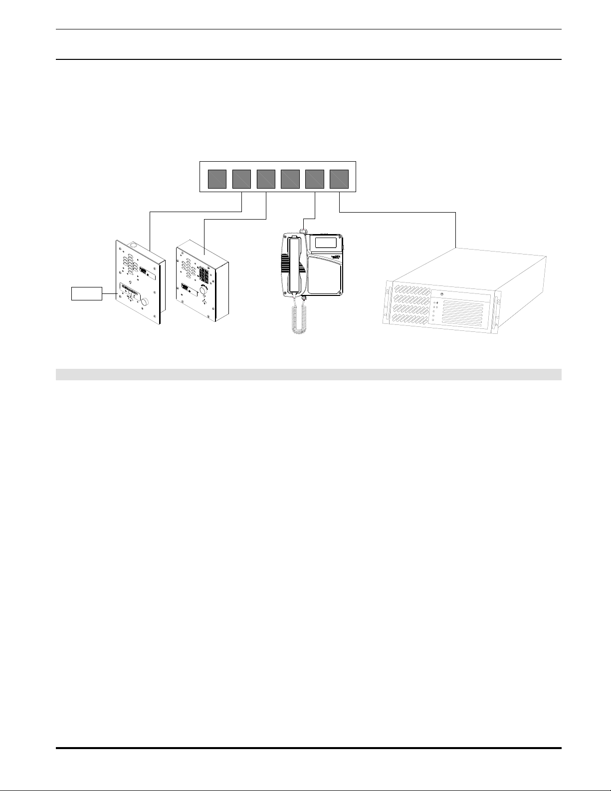
1. Typical System Installation ......................................................................................... 7
2. Operation.................................................................................................................... 7
3. Supported Protocols ................................................................................................... 7
4. Supported SIP Servers ............................................................................................... 7
5. Getting Started ........................................................................................................... 8
6. Configure the Telephone Parameters......................................................................... 8
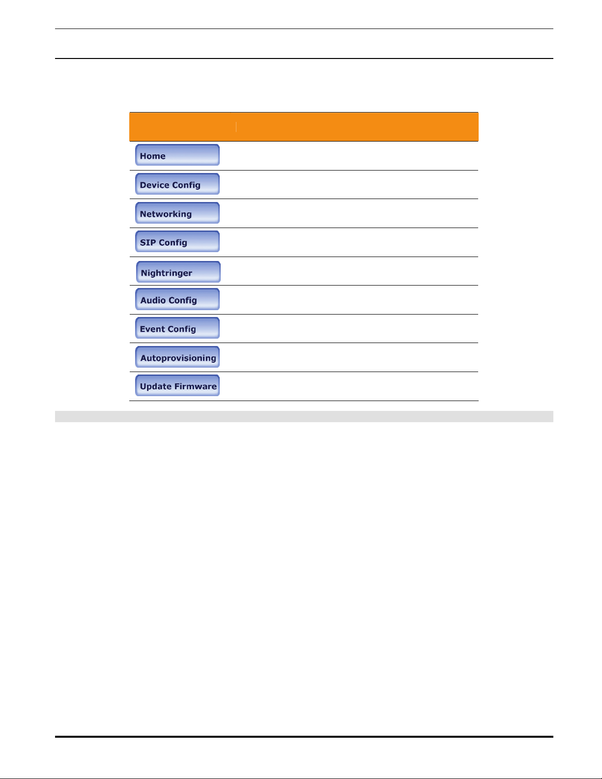
6.1. Telephone Web Page Navigation.................................................................... 9
6.2. Log in to the Configuration Home Page ........................................................ 10
6.3. Configure the Device Parameters ................................................................. 12
6.4. Configure the Network Parameters ............................................................... 14
6.5. Configure the SIP Parameters ...................................................................... 16
6.6. Configure the Nightringer Page..................................................................... 20
6.7. Configure the Audio Parameters ................................................................... 22
6.7.1. User-created Audio Files ...................................................................... 24
6.8. Configure the Event Parameters ................................................................... 26
6.9. Configure the Autoprovisioning Parameters.................................................. 30
6.10. Advanced Configuration (Debug) Page......................................................... 34
6.10.1. Reboot the Telephone .......................................................................... 36
7. Setting up a TFTP Server ......................................................................................... 36
7.1. In a LINUX Environment ............................................................................... 36
7.2. In a Windows Environment ........................................................................... 36
8. Discovery Process.................................................................................................... 37
8.1. Accessing webpage functionality without a browser ..................................... 37
8.2. RESET Switch............................................................................................... 37
8.3. Testing the hardware .................................................................................... 37
9. Frequently Asked Questions..................................................................................... 39
10. Product Specifications .............................................................................................. 41
Figures
Figure 1 - Typical Installation .............................................................................................. 7
Figure 2 - Startup Screen .................................................................................................... 8
Figure 3 - Home Page....................................................................................................... 10
Figure 4 - Device Configuration Page ............................................................................... 12
Figure 5 - Network Configuration Page ............................................................................. 14
Figure 6 - SIP Configuration Page .................................................................................... 16
Figure 7 - Nightringer Configuration Page......................................................................... 20
Figure 8 - Audio Configuration Page ................................................................................. 22
Figure 9 - Audacity 1 ......................................................................................................... 24
Figure 10 - Audacity 2 ....................................................................................................... 24
Figure 11 - WAV (Microsoft) signed 16 bit PCM................................................................ 25
Figure 12 - Event Configuration Page ............................................................................... 26
Figure 13 - Autoprovisioning Configuration Page.............................................................. 30
Figure 14 - Upgrade Firmware Page................................................................................. 32
Figure 15 - Advanced Configuration.................................................................................. 34

Guardian Telecom Inc. Setup & Configuration
VoIP Telephones
Page 6
Tables
Table 1 - Factory Default Settings.......................................................................................8
Table 2 - Telephone Web Page Navigation.........................................................................9
Table 3 - Home Page Overview ........................................................................................11
Table 4 - Device Configuration Parameters ......................................................................13
Table 5 - Network Configuration Parameters ....................................................................15
Table 6 - SIP Configuration Parameters............................................................................ 17
Table 7 - Nightringer Configuration Parameters................................................................21
Table 8 - Audio Configuration Parameters ........................................................................23
Table 9 - Event Configuration............................................................................................27
Table 10 - Autoprovisioning Configuration Parameters ..................................................... 31
Table 11 - Firmware Upgrade Parameters ........................................................................32
Table 12 - Advanced Configuration ...................................................................................35
Table 13 - Command Interface Post Commands .............................................................. 37
Acronyms
DHCP Server Dynamic Host Configuration Protocol
DHCPD Dynamic Host Configuration Protocol Daemon
DTMF Dual-tone Multi-frequency
HTTP Hypertext Transfer Protocol
IP Address Internet Protocol Address
LAN Local Area Network
LINUX Unix-like computer operating system
PBX Private Branch Exchange
PC Personal Computer
PCM Pulse-Code Modulation
PCMA Paired Carrier Multiple Access
PCMU Pulse Code Modulation mu-law
PoE Power over Ethernet
POST Power On Self Test
RIFF A short, repeated musical phrase
RTP Real-time Transport Protocol
RTP Port Real-time Transport Protocol port
AVP Audio Video Profile
SIP Session Initiation Protocol
TFTP Trivial File Transfer Protocol
URL Uniform Resource Locator
VoIP Voice Over Internet Protocol
WAV Waveform Audio File Format
WAVE Waveform Audio File Format
XML File Extensible Markup Language

Guardian Telecom Inc. Setup & Configuration
VoIP Telephones
1. Typical System Installation
The Voice-over-IP (VoIP) Telephone is a Power-over-Ethernet (PoE 802.3af) and Voice-over-IP (VoIP) two-way
communications device that easily connects into existing local area networks (LANs) with a single cable connection. The
telephone is compatible with most SIP-based IP PBX servers that comply with SIP RFC 3261.
Figure 1 illustrates how VoIP Telephones can be installed as part of a VoIP phone system.
123456
Generic PoE Hub
LAN1
LAN2
ALARM
EXTERNAL
DEVICES
Guardian VoIP Emergency Telephones Guardian VoIP Industrial Telephones IP PBX Server
Figure 1 - Typical Installation
as been properly installed and energized, operation is identical to most other single line
rface for easy system configuration and verification of a VoIP Telephone.
●DH
y assigns IP addresses in addition to the option to use static addressing.
●TF
hosting for the Autoprovisioning configuration file.
●RT
cilitates autoprovisioning configuration values on boot
●Au
mu-law)
ost IP PBX servers.
2. Operation
Once your VoIP Telephone h
telephones.
3. Supported Protocols
The VoIP Telephone with Keypad supports:
●SIP (Session Initiation Protocol)
●HTTP Web-based configuration
Provides an intuitive user inte
CP Client
Dynamicall
TP Client
Facilitates
P
Fa
dio Encodings
PCMU (G.711
PCMA (G.711 A-law)
Packet Time 20 ms
4. Supported SIP Servers
As a SIP device, this product will operate with m
Page 7

Guardian Telecom Inc. Setup & Configuration
VoIP Telephones
5. Getting Started
The Installation manual provided with the telephone provides information on installing and connecting the device to the server.
This manual describes the steps required to customize the telephone to suit the individual’s preferences.
The Discovery Utility is supplied on a CD and needs to be installed manually.
To access a VoIP phone for programming:
•Install the Guardian Discovery Utility onto the network server or SIP server.
•Start the Utility by double clicking the icon.
•Click on “Refresh List”.
•Click on the device to be programmed to highlight it.
•Click on “Launch Browser”.
Figure 2 - Startup Screen
6. Configure the Telephone Parameters
To configure the Telephone online use a standard web browser.
All Telephones are initially configured with the following default IP settings:
Parameter Factory Default Setting
IP Addressing DHCP
IP Addressa10.10.10.10
Web Access Username admin
Web Access Password admin
Subnet Maska255.0.0.0
Default Gatewaya10.0.0.1
Table 1 - Factory Default Settings
a. Default if there is not a DHCP server present.
When configuring more than one Telephone attach the Telephones to the network and configure one at a time to avoid IP
address conflicts.
Page 8

Guardian Telecom Inc. Setup & Configuration
VoIP Telephones
6.1. Telephone Web Page Navigation
Table 2 shows the navigation buttons that you will see on every Telephone web page.
Web Page Item Description
Link to the Home page.
Link to the Device Configuration page.
Link to the Networking page.
Link to the SIP Configuration page.
Link to the Nightringer Configuration page.
Link to the Audio Configuration page.
Link to the Event Configuration page.
Link to the Autoprovisioning Configuration page.
Link to the Update Firmware page.
Table 2 - Telephone Web Page Navigation
Page 9

Guardian Telecom Inc. Setup & Configuration
VoIP Telephones
6.2. Log in to the Configuration Home Page
1. Open your browser to the Telephone’s IP address. If you do not know the IP address, you can use the “Discovery
Utility” to detect all VoIP devices on the network. When opened the Discovery Utility scans the network for VoIP devices,
specifically Guardian VoIP devices.Individually select the device and launch the browser. Another method to obtain the IP
address is to press the RESET switch for approximately one second. The phone will speak the address through the
handset earpiece. The physical location of a telephone can be determined by comparing either the MAC Address, IP
Address or Serial Number shown on the Discovery Utility screen with the information on the unit.
Note: If the network does not have access to a DHCP server, the device will default to an IP address of
10.10.10.10.
Note: Make sure that the PC is on the same IP network as the Telephone.
2. When prompted, use the following default Web Access Username and Web Access Password to access the Home
Page (Figure 3):
Web Access Username: admin
Web Access Password: admin (Iower case)
3. On the Home Page, review the setup details and navigation buttons described in Table 3.
Note: The Screen Captures shown are only examples; refer to the tables for definitions.
Figure 3 - Home Page
Page 10

Guardian Telecom Inc. Setup & Configuration
VoIP Telephones
Web Page Item Description
Device Settings
Device Name: Shows the device name.
Change Username: Type in this field to change the username.
Change Password: Type in this field to change the password.
Re-enter Password: Type the password again in this field to confirm the new password.
Current Settings
Serial Number: Shows the device serial number.
Mac Address: Shows the device Mac address.
Firmware Version: Shows the current firmware version.
IP Addressing: Shows the current IP addressing setting (DHCP or static).
IP Address: Shows the current IP address.
Subnet Mask: Shows the current subnet mask address.
Default Gateway: Shows the current default gateway address.
DNS Server 1: Shows the current DNS Server 1 address.
DNS Server 2: Shows the current DNS Server 2 address.
Speaker Volume: Shows the current speaker volume level.
Handset Volume: Shows the current handset volume level.
Microphone Gain: Shows the current microphone gain level.
Handset Gain: Shows the current handset gain level.
SIP Mode is: Shows the current SIP Mode status.
Event Reporting is: Shows the current Event Reporting status.
Nightringer is: Ringtone broadcast when enabled and extension is called.
Primary SIP Server: Primary SIP Server
Backup Server 1: Redundant SIP Server “1”
Backup Server 2: Redundant SIP Server “2”
Click the Save button to save your configuration settings.
Note: You need to reboot for changes to take effect.
Click on the Reboot button to reboot the system.
Table 3 - Home Page Overview
Page 11

Guardian Telecom Inc. Setup & Configuration
VoIP Telephones
6.3. Configure the Device Parameters
1. Click the Device Configuration button to open the Device Configuration page. See Figure 4.
Figure 4 - Device Configuration Page
2. On the Device Configuration page, you may enter values for the parameters indicated in Table 4.
3. After changing the parameters, click the Save button.
Page 12

Guardian Telecom Inc. Setup & Configuration
VoIP Telephones
Web Page Item Description
Volume Settings
The volume settings describe the volume set on reboot. The user can change the
volume by using the up and down arrows, but this change is temporary and the
volume will be reset when the device is rebooted.
Hands Free Speaker Volume:
The speaker volume sets the initial volume of the device on boot. Valid values are 0-9.
Test the speaker volume using the ‘Test Audio’ button below. Saving changes to the
speaker volume will take effect immediately (it does not require a restart).
Hands Free Microphone Gain:
The microphone gain sets the initial input gain of the on board microphone. Valid
values are 0-9. Test the speaker volume using the ‘Test Microphone’ button below.
Saving changes to the speaker volume will take effect immediately (it doesn’t require a
restart).
Handset Volume:
The handset volume sets the initial volume of the handset on boot. Valid values are 0-
9. Saving changes to the handset volume will take effect immediately (it does not
require a restart).
Handset Gain:The range of the handset gain is limited by the hardware and there are only three
volume levels available (low, medium, and high).
Relay Settings
Activate Relay with DTMF Code: When this option is enabled, the device will activate the relay when it receives a DTMF
code (rfc2833).
DTMF Activation Code: This 25 character field can be used a set a DTMF code used to activate the relay.
DTMF Activation Duration (in
seconds):
When the relay is activated with a DTMF code, it will remain active for this duration in
seconds. Valid values are 1-9.
NOTE: A DTMF activation of 0will toggle the relay indefinitely or until the activation
code is sent again.
Activate Relay During Ring:When this option is enabled, the relay will activate when
the device has received a call and is playing a ringtone.
Activate Relay During Night Ring:When this option is enabled, the relay will activate when
the device has received a call to the night ring extension.
Pulse Relay when Ringing: When a “ring” is present the relay will pulse with a cadence of 2 seconds on, 3
seconds off.
Pulse Buzzer when Ringing: When a “ring” is present the internal ringer will pulse with a cadence of 2 seconds on,
3 seconds off.
Activate Relay While Call Active:When this option is enabled, the relay will activate when a call is established with
another SIP device. It will remain active for the duration of the call.
Miscellaneous Settings
Auto-Answer Incoming Calls:
When this option is enabled, the device will automatically answer incoming calls.
When the handset is on hook, the call will be established using the hands free speaker
and microphone.
Backlight On:This option sets the normal state of the backlight after the device has booted.
This button will play an audio test message and can be used to test the volume level.
When this button is pressed the device will record 3 seconds of audio, beep, and then
play back the recorded audio. This can be used to test the microphone gain level.
This button will activate the relay for the DTMF activation Duration (in seconds).
When this button is toggled, it will put the device into button test mode. In this mode,
the handset or hands free speaker will play an audio file when a button is pressed on
the device. For normal keypad input (keys 0-9) it will speak the associated file from the
audio configuration page. For the other keypad keys, (*, #, any other function keys) it
will play a DTMF tone while the button is depressed. The button press mode will time
out after 60 seconds.
Click the Save button to save your configuration settings.
Note: You need to reboot for changes to take effect.
Click on the Reboot button to reboot the system.
Table 4 - Device Configuration Parameters
Page 13

Guardian Telecom Inc. Setup & Configuration
VoIP Telephones
6.4. Configure the Network Parameters
1. Click the Networking button to open the Network Configuration page (Figure 5).
Figure 5 - Network Configuration Page
2. On the Network Configuration page, enter values for the parameters indicated in Table 5.
3. After changing the parameters, click Save Settings. This updates the changed parameters and reboots the Telephone
if appropriate.
4. Connect the Telephone to the target network.
5. From a computer on the same network as the Telephone, open a browser with the new IP address of the Telephone.
Page 14

Guardian Telecom Inc. Setup & Configuration
VoIP Telephones
Web Page Item Description
Stored Network Settings Shows the settings stored in non-volatile memory.
IP Addressing:
This setting is used to configure the device to use the static IP address
configured below or to fetch its address from a DHCP server on the network.
When the device is plugged into a network without a DHCP server, it will
request an address 12 times over the course of 60 seconds before it will fall
back on the last known good DHCP address, or if it has never had a DHCP
address, to the stored static IP address (by default 10.10.10.10).
IP Address: The IPV4 static IP address in standard dotted decimal notation.
Subnet Mask: The IPV4 routing prefix in standard dotted decimal notation.
Default Gateway: This is the node to go to when an IP address doesn’t match any routes in the
routing table. This requires standard quad-dotted decimal notation.
DNS Server 1:
DNS Server 2:
The DNS server configuration is used to setup the primary and secondary name
servers for the network. These use standard dotted decimal notation.
Current Network Settings Shows the current network settings.
IP Address: Shows the current Static IP address.
Subnet Mask: Shows the current Subnet Mask address.
Default Gateway: Shows the current Default Gateway address.
DNS Server 1: Shows the current DNS Server 1 address.
DNS Server 2: Shows the current DNS Server 2 address.
Click the Save button to save your configuration settings.
Note: You need to reboot for changes to take effect.
Click on the Reboot button to reboot the system.
Table 5 - Network Configuration Parameters
Page 15

Guardian Telecom Inc. Setup & Configuration
VoIP Telephones
6.5. Configure the SIP Parameters
1. Click SIP Config to open the SIP Configuration page (Figure 6).
Note: Guardian VoIP telephones are compatible with most SIP servers.
Figure 6 - SIP Configuration Page
2. On the SIP Configuration page, enter values for the parameters indicated in Table 6.
3. After changing the parameters, click Save Settings
Page 16

Guardian Telecom Inc. Setup & Configuration
VoIP Telephones
Page 17
Table 6 - SIP Configuration Parameters
Web Page Item Description
Enable SIP Operation:
When this option is enabled, the device will initialize the SIP engine
and try to register with a SIP server or listen for incoming SIP
connections.
SIP Settings
SIP Server
The SIP server is used to set the address (in dotted decimal
notation or as a canonical name) of the SIP registrar. This field can
accept canonical names of up to 255 characters in length.
Backup SIP Server 1:
The SIP server is used to set the address (in dotted decimal
notation or as a canonical name) of the SIP registrar. This field can
accept canonical names of up to 255 characters in length.
Backup SIP Server 2:
The SIP server is used to set the address (in dotted decimal
notation or as a canonical name) of the SIP registrar. This field can
accept canonical names of up to 255 characters in length.
Remote SIP Port: The Remote SIP Port is used to set the port number that the SIP
registrar uses for SIP traffic.
Local SIP Port: The Local SIP Port is used to set the port number this device will
use to listen for and transmit SIP traffic.
Outbound Proxy:
The Outbound Proxy Port is an optional field only filled in if a Proxy
server is used for SIP communications. It is used to set the port
number of the Proxy Server.
Outbound Proxy Port: Type the Outbound Proxy Port number (8 character limit).
SIP User ID: The SIP User ID is the user part of a SIP address, generally this is
the extension number of the device.
Authenticate ID:
The Authenticate Password is the password used for authentication
by the SIP server. If authentication is not configured on the SIP
server, this field should be blank.
Authenticate Password:
The Authenticate Password is the password used for authentication
by the SIP server. If authentication is not configured on the SIP
server, this field should be blank.
Register with a SIP Server:
When this option is enabled, the device will try to register with the
SIP server and credentials (given above) on boot. When the device
has successfully registered with a SIP server, it will show its status
at the top of the page. When this option is disabled, the device will
operate in point to point (P2P) mode. In this mode, the device can
connect to other SIP devices without using a SIP server as an
intermediary. This option only exists when using the speed dial
option on the button configuration page. Instead of putting an
extension in these fields, use a IP address.
Note: Some phones do not support placing or receiving calls to a
device rather than a SIP server.
Re-registration Interval (in
seconds):
The re-registration interval determines how often the device will
attempt to re-register with the SIP server. Valid values are 100-
3600 seconds. Some SIP servers may request a device register
more or less often than the value configured here.
Unregister on Reboot:
If Unregister on Reboot is checked, this device will attempt to send
a remove all register request to the SIP server upon booting. Please
note that if the SIP server does not support this unregister request,
it may cause some problems.

Guardian Telecom Inc. Setup & Configuration
VoIP Telephones
Autodial Settings
Keypad AD Enter the speed dial extension that is to be used when the user
presses the Ml button.
ID:Password for Keypad AD extension. If authentication is not
configured on the SIP server, this field should be blank.
Ringdown Settings
Ringdown If used the telephone will autodial that extension after handset has
been taken off-hook.
ID:Password for Ringdown extension. If authentication is not
configured on the SIP server, this field should be blank.
Misc Settings
RTP Port (even) :
The RTP Port field is used to set the port pair that this device will
use for listening for and transmitting RTP and RTCP traffic. This
field sets the RTP port. This field +1 sets the RTCP port. Per the
RFCS55O specification, the RTP port should be even, but an odd
port number is allowed.
Play Button Tone:When selected, you will hear a button tone when a keypad button is
pressed.
Click the Save button to save your configuration settings.
Note: You need to reboot for changes to take effect.
Click on the Reboot button to reboot the system.
Page 18

Guardian Telecom Inc. Setup & Configuration
VoIP Telephones
Page 19
THIS PAGE INTENTIONALLY LEFT BLANK

Guardian Telecom Inc. Setup & Configuration
VoIP Telephones
6.6. Configure the Nightringer Page
Click the Nightringer button to open the Nightringer Configuration page (Figure 7).
On the Nightringer Configuration page you may enter values for the parameters indicated in Table 7.
Figure 7 - Nightringer Configuration Page
Page 20
Table of contents
Other Guardian IP Phone manuals