Gude Expert Power Control 8090 GSM User manual

User Manual
Expert Power Control 8090 GSM
© 2019 GUDE Systems GmbH
Manual Ver. 1.2.1
valid from Firmware Ver. 2.0.2

Have your Gude devices always in view - and in control.
With the free Gude Control App you can retrieve all relevant information
from your GUDE products regardless of their current whereabouts.
Check with your smartphone the important operating figures of your
server and rack environment like sensor values (max/min), energy
consumption as well as state of inputs and outputs with watchdog
functions. In particular, connected consumers can be switched remotely
with Gude Control.
"Gude Control" is available for the Expert Power Control 8090 GSM and
can be free downloaded from the Google Play Store and iTunes Store.

3
Expert Power Control 8090 GSM Table of contents
Table of contents
Chapter 1 Device Description 5
5
1.1 Security Advice
5
1.2 Content of Delivery
5
1.3 Description
6
1.4 Installation
7
1.5 Status LED
7
1.6 Bootloader Mode
9
1.7 Firmware-Update
9
1.8 Technical Specifications
10
1.9 Sensor
Chapter 2 Operating 11
11
2.1 Operating the device directly
12
2.2 Operating by Webinterface
13
2.3 GSM
2.3.1 SMS 14
2.3.2 Voice Call 20
2.3.3 Power Port Commands 24
2.3.4 Security 26
Chapter 3 Configuration 26
27
3.1 Configuration by Software
28
3.2 Configuration via Webinterface
3.2.1 Configuration - Power Ports 29
3.2.2 Configuration - Watchdog 30
3.2.3 Configuration - IP Address 31
3.2.4 Configuration - IP ACL 32
3.2.5 Configuration - HTTP 33
3.2.6 Configuration - Sensors 34
3.2.7 Configuration - SNMP 35
3.2.8 Configuration - Syslog 36
3.2.9 Configuration - E-Mail 36
3.2.10 Configuration - GSM 37

5
Expert Power Control 8090 GSM Device Description
Device Description
1
Security Advice
1.1
·The device must be installed only by qualified personnel according to the following installation and
operating instructions.
·The manufacturer does not accept responsibility in case of improper use of the device and particu-
larly any use of equipment that may cause personal injury or material damage.
·The device contains no user-maintenable parts. All maintenance has to be performed by factory
trained service personnel.
·This device contains potentially hazardous voltages and should not be opened or disassembled.
·The device can be connected only to 230V AC (50Hz or 60 Hz) power supply sockets.
·The power cords, plugs and sockets have to be in good condition. Always connect the device to
properly grounded power sockets.
·The device is intended for indoor use only. Do NOT install them in an area where excessive mois-
ture or heat is present.
·Because of safety and approval issues it is not allowed to modify the device without our permission.
·Please note the safety advises and manuals of connected devices, too.
·The device is NOT a toy. It has to be used or stored out or range of children.
·Care about packaging material. Plastics has to be stored out of range of children. Please recycle
the packaging materials.
·In case of further questions, about installation, operation or usage of the device, which are not clear
after reading the manual, please do not hesitate to ask our support team.
·Please, never leave connected equipment unattended, that can cause damage.
·Connect only electrical devices that do not have limited on-time. I.e. in case of failure, all connected
appliances have to cope with a continuous on-time without causing damage.
·The human head should always be kept more than 30cm away from the built-in GSM modem.
·Connect only electrical devices that do not have limited on-time. I.e. in case of failure, all connected
appliances have to cope with a continuous on-time without causing damage.
Content of Delivery
1.2
The package includes:
·Expert Power Control 8090 (EPC8090)
·CD-ROM with Manual and Software Tools
·Power Supply cable (max. 16A)
·GSM antenna
What you still need to use all the features of the EPC8090
·SIM Card (prepaid or contract)
Description
1.3
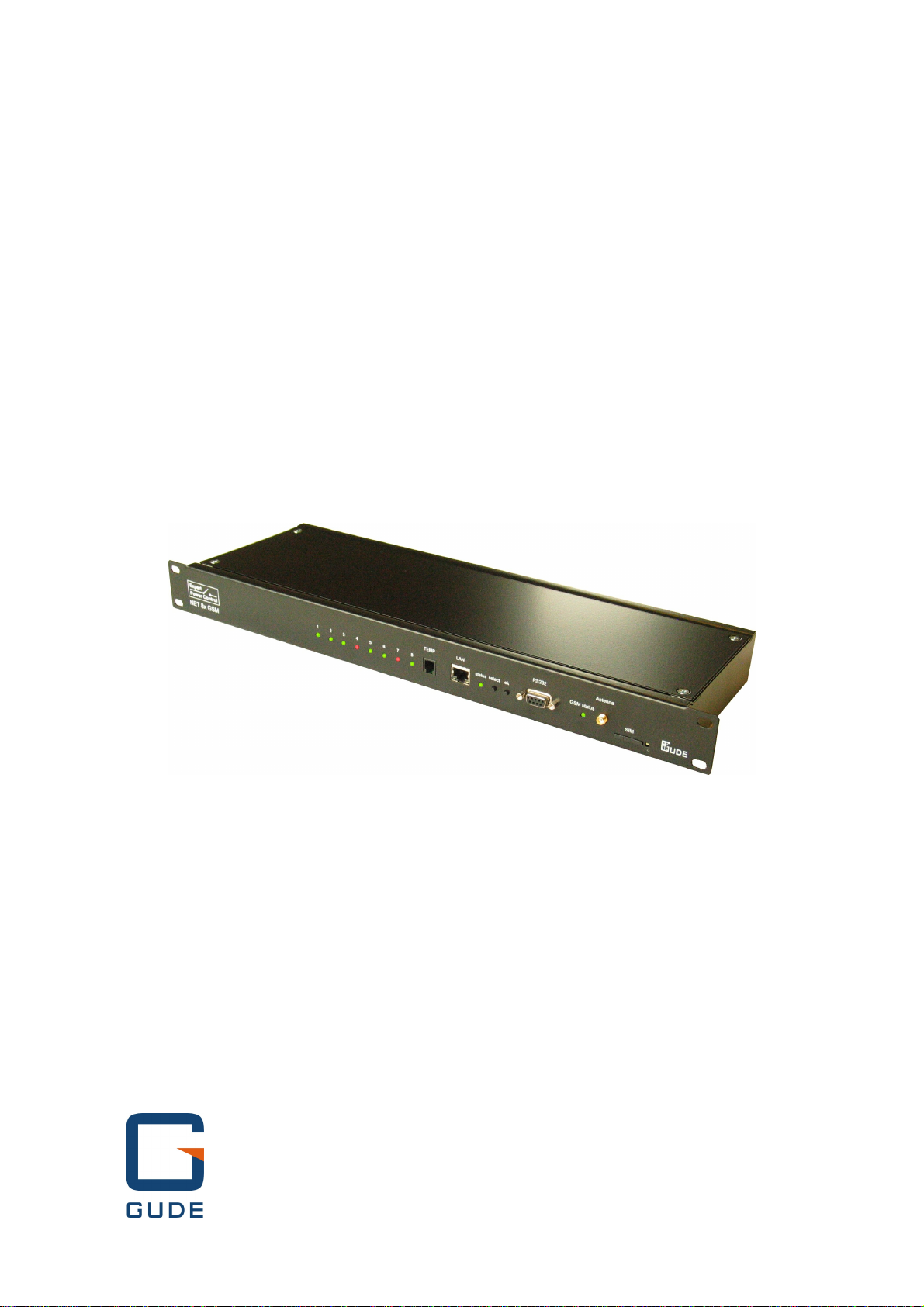
The Expert Power Control (EPC) 8090 is a switchable power distribution unit, that can remote switch
other devices in the power grid. The EOC8090 has the following features:
·Switching of 8 load outputs (230V, 10A).
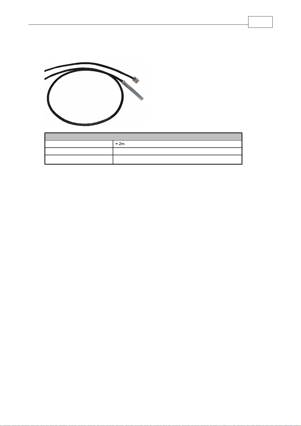
·Connects to an external sensor to measure temperature values.
·Control and monitor the device via Ethernet with an integrated web server and SNMP (v1 and v2c).

6
Expert Power Control 8090 GSM Device Description
·The device has a built-in GSM modem, which allows the control of the device. One can thus control
the EPC8090 via SMS, Data Call and Voice Call with DTMF tones.
·When switching the relays and reaching the limits of the external sensor, messages are generated.
These messages can be sent by e-mail, syslog, SNMP traps and SMS.
Installation
1.4
1. Status LED output indicator (green - output switched)
2. Temperature sensor connector (RJ11)
3. Ethernet connector (RJ45)
4. Status LED
5. Select button
6. Ok button
7. RS232 Connector (D-SUB)
8. Status LED GSM connection
9. GSM antenna connector
10.SIM Card
11. Eject button for SIM Card
12. Power supply (IEC C20, max.16A)

7
Expert Power Control 8090 GSM Device Description
13. 8 x Load outputs (IEC C13, max. 16A)
Start-up the device
·Connect the power cord of the unit to the mains supply.
·Plug the network cable into the Ethernet connector (RJ45).
Status LED
1.5
The Status LED shows different states of the device:
·red: Device is not connected to the Ethernet
·orange: Device is connected to the Ethernet, TCP/IP settings are not allocated
·green: Device is connected to the Ethernet, TCP/IP settings allocated
·periodic blinking: Device is in Bootloader mode.
The GSM status LED describes the reception situation of the GSM module:
·off: The GSM module is switched off.
·red: The GSM module is switched on but has no GSM reception.
·flashing red: The module has poor reception.
·flashing orange: The module has moderate reception.
·flashing green: The module has good reception.
There are three LEDs mounted on the device (traffic light) that show the load condition in addition to
the website:
green: Less than 10A is flowing through the power strip.
Yellow: The load on the device is between 10A and 14A.
flashing red: There is more than 14A load connected.
Bootloader Mode
1.6
Certain actions can, for safety reasons, only be carried out if the device is in bootloader mode. The
following operations are possible only in Bootloader Mode:
·Firmware Update
·Configuration with GBL_Conf.exe
·Factory Reset
Activation of the Bootloader Mode
via push button:
·Hold both buttons for 3 seconds (only if the device has 2 buttons)
or
·Remove the power supply

8
Expert Power Control 8090 GSM Device Description
·Hold down the button (or the "Select" button for devices with 2 buttons). If the push button is re-
cessed, use a pin or paper clip
·Connect the operating voltage
by Software: (only if "Enable FW to BL" was previously activated in GBL_Conf.exe)
·Start GBL_Conf.exe
·Do a network search with the "Search" menu action
·Activate in menu "Program Device" the item "Enter Bootloader"
Whether the device is in bootloader mode, is indicated by the flashing of the status LED, or it is
shown in GBL_Conf.exe, after a renewed device search, with the appendix "BOOT-LDR" after the
device name. In bootloader mode the program GBL_Conf.exe can disable the password and the IP
ACL, perform a firmware update, and restore the factory settings.
Activation of the bootloader mode and an abandonment of the bootloader does not change
the state of the power or output ports as long as the supply voltage is maintained.
Abandonment of the Bootloader Mode
via push button:
·Hold both buttons for 3 seconds (only if the device has 2 buttons)
or
·Remove and connect the power supply without operating a button
by Software:
·Start GBL_Conf.exe
·Do a network search with the "Search" menu action
·In menu "Program Device" activate the item "Enter Firmware"
Factory Reset
If the device is in bootloader mode, it can always be put back to its factory default. All TCP / IP set-
tings are reset in this operation.
via push button:
·Activate the Bootloader Mode of the device
·Hold down the button (or the "Select" button for devices with 2 buttons) for 6 seconds. If the push
button is recessed, use a pin or paper clip
·The status LED will blink in a fast rhythm, please wait until the LED blinks slowly (about 5 seconds)
by Software:
·Activate the Bootloader Mode of the device
·Start GBL_Conf.exe
·In menu "Program Device" activate the item "Reset to Fab Settings"
·The status LED will blink in a fast rhythm, please wait until the LED blinks slowly (about 5 seconds)

9
Expert Power Control 8090 GSM Device Description
Firmware-Update
1.7
To perform a firmware update, the program GBL_Conf.exe and the latest firmware is needed.
Enable the bootloader mode (see Chapter Bootloader Mode)
Start GBL_Conf.exe
Select the device for which a firmware update is to be performed
Click "Program Device" and then select there "Firmware Update"
Specify the firmware file that should be uploaded
Upon completion of the update process, please start the new firmware of the device. You can do this
by simply leaving the bootloader mode.
A firmware update, unlike other functions, is not sent as a network broadcast. Therefore, the device
must have a valid IP address and a valid netmask before the firmware update. If necessary, please
correct the entries in GBL_Conf.exe in bootloader mode and save them with "Save Config".
If after a firmware update, the web page is not displayed correctly anymore, this may be related to the
interaction of Javascript with an outdated browser cache. Not always helps a Ctrl-F5, it is recommen-
ded that you manually delete the cache in the browser options. Alternatively, you can test start the
browser in "private mode".
Technical Specifications
1.8
Interfaces
1 x Ethernet port (RJ45)
1 x Serial connector (D-SUB, RS232)
1 x Power supply (IEC C20, max.16A)
3 x Load outputs (IEC C13, max. 16A)
1 x RJ11 for external sensor
1 x SMA Connector for GSM antenna
1 x SIM card slot
Network connectivity
10/100 MBit/s 10baseT Ethernet
Protocols
TCP/IP, HTTP, DHCP, ICMP,
SNMP v1/v2c + traps, Syslog, SMTP
GSM Modem
Triband GSM Module (900/1800/1900 MHz)
Sim Card
Mini-SIM
Environment
·Operating temperature
·Storage temperature
·Humidity
0°C - 50°C
-15°C - 60°C
10% - 85%
Case
Powder Coated Metal
Measurements
19" (inches), 1 Rack Unit, (Depth 155mm)
Weight
approx. 2.8kg

10
Expert Power Control 8090 GSM Device Description
Sensor
1.9
An external sensor can be connected to the EPC 8090. The following sensors are currently available
Temperature-Sensor 7000
Cable length
Connector
RJ11
Measurement range
-20°C to +80°C at ±3°C (maximum) and ±2°C (typical)

11
Expert Power Control 8090 GSM Device Description
The sensor is automatically detected after connect.
Operating
2
Operating the device directly
2.1
The current status of the output is indicated by the color of the LED. Red indicates that the output is
off, green shows that the output is on. On the device are the buttons "select" and "ok". If you press
"select", the LED will blink for the first output, ie the output is selected. Press "select" again to select
the next output. Hold down the button "ok" for two seconds, then the status of the selected output is
toggled.

12
Expert Power Control 8090 GSM Operating
Operating by Webinterface
2.2
Access the web interface: http://"IP-address" and log-in.
The website offers an overview of the port status, measurements and sensors, if they are connected.
Furthermore, there are buttons to control the state of the ports. The ports can be switched manually
with the "On" and "Off" buttons. If the port is turned on, it can be turned off by pressing the "Reset"
button, until after a delay it turns itself on again. The delay time is determined by the parameter Reset
Duration, which is described in the chapter about configuration via web interface.
Batchmode
Each individual port can be set for a selectable period of time to the state "switch on" or "switch off".
After the selected time they are automatically switched to the second preselected state.

13
Expert Power Control 8090 GSM Operating
Optionally the device can be switched via a Perl script or external tools like wget. More information is
available on our support wiki at www.gude.info / wiki.
GSM
2.3
To use the GSM functions, there must be an activated SIM card in the SIM card slot located on the
front of the unit.
If the SIM card is inserted, and the device is enabled, the integrated GSM module searches automat-
ically for a connection to the GSM network. If this connection works, you can control and configure
the device via SMS or by call.
When operating via SMS, send defined SMS commands to the device. The device executes these
commands and confirms them with reply SMS.
When operating via phone call, you can perform commands by FreeCall, that allow the unit to per-
form preconfigured commands, when it is called from a particular phone number. There is no connec-
tion established and there are no call charges. Another possibility is the voice call. Here, the device
menu is operated using DTMF codes. This type of operation can also be carried out automatically.
Preparing for GSM operation
If you are using a new SIM card, please take note:
1. Preparing the SIM card
·If you are using a contracted SIM card, please start with step 2
·If you are using a prepaid SIM card, please take care:
oThere has to be a positiv balance on the card
oThe card has to be activated. New prepaid cards need some manual operation
at the start of usage. These requests have to be made from a user with a cell-
phone.
2. SIM-card pin code
·The device awaits the SIM card pin code 1234 first. Enter this PIN to the SIM card, by
using a cellphone. In case you are using another pin code, you have to configure the
EPC NET GSM before you activate the GSM part of the device! Otherwise this may
lead to a lock of the SIM card.
·You can disable the need to enter the PIN code on the SIM card with a mobile phone.
In this case the EPC NET GSM accepts the SIM card without checking the code.
3. Install SIM card
·Switch off the device or deactivate the GSM module. Alternatively, you can just turn off
the GSM module in the EPC NET GSM via software. Never install a SIM card, when
GSM module is active. Otherwise the SIM card may be destroyed.
·Release the SIM card holder by pressing the yellow button with a fine stick. Insert the
SIM card in the ejected plastic tray and slide it back inside until it stops.
4. Connect Antenna

14
Expert Power Control 8090 GSM Operating
·Take the GSM antenna from the box and screw it to the EPC NET GSM by turning
clockwise. It is enough to attract the connection hand-tight. Never use pliers to tighten
or similar to the antenna, thus inevitably destroying the antenna connection.
5. Activate the EPC NET GSM
·Power up the device. In factory default state, the GSM module is deactivated. This is a
security setting in delivery to avoid accidentally locking a SIM card with the wrong
code.
·Log in on the web interface.
·Switch to Configuration / GSM / SIM.
·Here the button "Enable GSM" is set to "No", that is the GSM module is turned off. Set
the button to "yes", then press the button "Apply" to transmit the data to the EPC NET
GSM.
·Wait some minutes, until the device has logged into the GSM. You can see the status
change from the flashing GSM status LED or in the web interface.
GSM Status LED
The GSM status LED displays different states of the GSM module.
LED off
GSM module is deactivated.
LED permanent red
GSM module activated, looking for GSM signal.
LED blinks red
GSM module activated, bad receive quality.
LED permanent orange
GSM module activated, medium receive quality.
LED blinks green
GSM module activated, good receive quality.
The quality of the GSM signal can also be checked in the web interface in the Control Panel.
SMS
2.3.1
SMS Commands2.3.1.1
Description of the SMS format to send commands to the device:
Format
%[cmd-name] [param 1] [...] [param N] {param 1} {...} {param N}
[param x] = mandatory parameter
{param x} = optional paramater
If activated, a port code or master code will be required. Entering these codes is initiated by p(for
Port code) or m(for Master code).

15
Expert Power Control 8090 GSM Operating
2.3.1.1.1 Powerport: Query Power Port State
Format
%port state [portnumber] {Portcode/Mastercode}
Command:
Request of status of Power Port 1, Portcode 1111
%port state 1p1111
Answer:
Device name: epc007
Powerport state: Port 1 on
Account credit: Credit: 130.50 Eur
2.3.1.1.2 Powerport: Simple Switching
Format
%port [on, off, toggle] [portnumber] {Portcode/Mastercode}
Examples:
Switch off Power Port 2, Mastercode 2222
%port off 2 m2222
Toggle Power Port 8, Portcode 1238
%port toggle 8 p1238
Reset Power Port 6, Portcode 0123
%port reset 6 p0123
Switch on Power Port 1, without Portcode
%port on 1
Answer (example):
Device name: epc007
Power switch: Port 1 off -> on
Account Credit: Credit: 130.50 Eur
2.3.1.1.3 Powerport: Advanced Switching (Batchmode)
Format
%port batchmode [portnumber] [batch-sequence-number] {Portcode/Mastercode}
[batch-sequence-number]
'11' .. '19' off, wait [t1 .. t9]s, on
'21' .. '29' on, wait [t1 .. t9]s, off
'31' .. '39' toggle, wait [t1 .. t9]s, toggle
Note: Sequence numbers are identical to the DTMF codes for voice calls.

16
Expert Power Control 8090 GSM Operating
tn
Time in seconds
t1
1
t2
2
t3
5
t4
10
t5
20
t6
60
t7
120
t8
240
t9
480
Example:
%port batchmode 1 13 m0123
Answer:
Device name: epc007
Switch sequence: Port 1 off -> t3 -> on
Account Credit: Credit 130.50
2.3.1.1.4 Powerport: Advanced Switching (coldstart)
The command 'coldstart' turns off all Powerports at once. Then it switches the ports temporally
delayed on again (according to the current power port configuration), as if the device performs a cold
start.
Format
%coldstart {mastercode}
Example:
%coldstart m0123
Answer:
Device name: epc007
Switch sequence: coldstart
Account Credit: Credit: 130.50 Eur
2.3.1.1.5 Configuration: Read
Format
%config get [config-name] {mastercode}
[config-name ]:
all
code
telbook
gsmstatus
temp
response
error
portname
adminnum
tempmin
tempmax
17

17
Expert Power Control 8090 GSM Operating
gsm
Example:
%config get code m1234
Answer:
Config: code = on
Example:
%config get all
Answer:
Config: code = on
telbook = off
[...]
adminnum = 0161123456
gsm = on
2.3.1.1.6 Configuration: Write
Format
%config set [config-name] [config-value] {Mastercode}
[config-name] :
code
telbook
gsmstatus
temp
response
error
portname
adminnum
tempmin
tempmax
gsm
Example:
%config set code off m1234
Answer:
Config: code = off
2.3.1.1.7 Configuration: All Parameter
Description
SMS [config-name]
SMS [config-value]
default
Master/Port
Code enabled?
code
on, off
off
Check of phone
book?
telbook
on, off
off
Send GSM
Status SMS to
'adminnum'
gsmstatus
on, off
off
17

18
Expert Power Control 8090 GSM Operating
Description
SMS [config-name]
SMS [config-value]
default
Send SMS to
'adminnum' if
tempmin / temp-
max are changed
temp
on, off
off
Send SMS reply
on SMS com-
mands to recent
SMS user
response
on, off
on
Send SMS reply
with error mes-
sage, if SMS
command was
malformed
error
on, off
on
States con-
figured Port
name instead of
Power Port n in
SMS replies
portname
on, off
off
Allow deactiva-
tion of GSM
module via SMS
gsm
on, off
off
Phone number
for e-mail mes-
sages
email
max. 15 chars
Access only for
admin
mastergsm
on, off
off
Autosync
autosync
on, off
off
DTMF for
VoiceCall
calltone
on, off
off
Voice for
VoiceCall
callvoice
on, off
on
Phone number
for SMS mes-
sages
adminnum
max. 15 chars
Minimum value
for temperature
alerts
tempmin
'-20' .. '0'
0
Maximum value
for temperature
alerts
tempmax
'0' .. '90'
50
Allows freecall
operation
freecall
on, off
off
2.3.1.1.8 Sensors: Query State
Format
%sensor state [portnumber, all] {Mastercode}
Example:
Query the state of all sensors, Mastercode 0000

19
Expert Power Control 8090 GSM Operating
%sensor state m0000
Answer:
Device name: epc007
Port: Sensor port 1
Sensor name: Temperature
Value: NC
Port: Sensor port 2
Sensor name: Temperature
Value: T=22.79C
Value: RH= 76.64%
Account credit: Credit: 130.50 Eur
2.3.1.1.9 Query Device State
Format
%all state {Mastercode}
Example:
Query the state of the device:
%all state
Answer:
Device name: epc007: Status
Outputport state: outp: 1=On 2=On 3=On 4=Off
Inputport state: dinp: 1=Off 2=Off 3=Off 4=Off
Sensor Port 1: senp 1: NC
Sensor Port 2: senp 2: T=22.79C RH= 76.64%
Account credit: Credit: 130.50 Eur
SMS replies2.3.1.2
2.3.1.2.1 SMS command replies
A command reply SMS looks like:
Device name: [name]
prefix
[response text]
Command specific reply
Account credit: [x]
[response text]
Device name: [name]
Power switch: [powerport] [s] -> [s]
[powerport] = Port 1 .. Port 99 (or Config:portname)
[s] = on .. off
Powerport state: [powerport] is [s], [...], [powerport] is [s]
[powerport] = Port 1 .. Port 99 (or Config:portname)
[s] = on .. off
Switch sequence: [s]
[s]

20
Expert Power Control 8090 GSM Operating
[powerport] [c] -> wait t -> [c]
[powerport] = 'Port 1' .. 'Port 99' (or Config:portname)
[c] = on, off, toggle, coldstart
Account credit: [x]
Config: name = value, [...], name = value
or
command parse error
2.3.1.2.2 Status Change Report SMS
A SMS status change request reply looks like:
Device name: [name]
Prefix
[response text]
Status change request specific reply
Account credit: [x]
[response text]
Device name: [name]
[powerport] -> [s]
[powerport] = 'Port 1' .. 'Port 99' (or Config:portname)
[s] = 'on' .. 'off'
[powerport] [s]
[powerport] = 'Port 1' .. 'Port 99' (or Config:portname)
[s] = batchmode, toggled, Coldstart
Temperature state: [val]
[val] = 'over the MAX limit', 'under the MIN limit'
Account credit: [x]
Voice Call
2.3.2
Menu2.3.2.1
For operating with VoiceCall, simply call the phone number of the SIM card of the GSM module.
When connection is established the device replies with the announcement: "Main menu" and a DTMF
tone
In the menu the navigation works via DTMF commands.
Each command starts with # and ends with *.
Numbers
Men
*1#
Power Port
*2#
Input Port
*8#
Status
Table of contents
Other Gude Power Distribution Unit manuals