Gym Master GateKeeper h4.2 User manual

Preface 2
Hardware Checklist 2
GateKeeper Overview 3
Power Supply 4
GateKeeper Interface 5
Relay Terminals 5
Exit Button Terminals 6
RFID Reader Sockets 6
Sample Wiring Diagrams 8
Fail-Secure 9
Fail-Secure with Emergency Exit 10
Fail-Safe 11
Fail-Safe with Emergency Exit 12
Combinations of Relay Units 13
Bi-Directional 13
Normally Open Contacts 13
Normally Closed Contacts 13
GateKeeper Status 14
What Do the Lights Mean? 14
Troubleshooting 15
Test the relay wiring to the magnet lock 15
EPIC Sanctuary
78-106 Manchester St
Christchurch 8011
New Zealand
PO Box 13352
Armagh Mail Centre
Christchurch 8011
New Zealand
www.gymmastersoftware.com
NZ 03 974 9169
AU 03 9111 0323
US 415 678 1270
Page 1

Preface
This wiring guide is for the technician or electrician responsible for installing the GateKeeper h4.2,
door readers, and access control units as supplied by Treshna Enterprises Ltd.
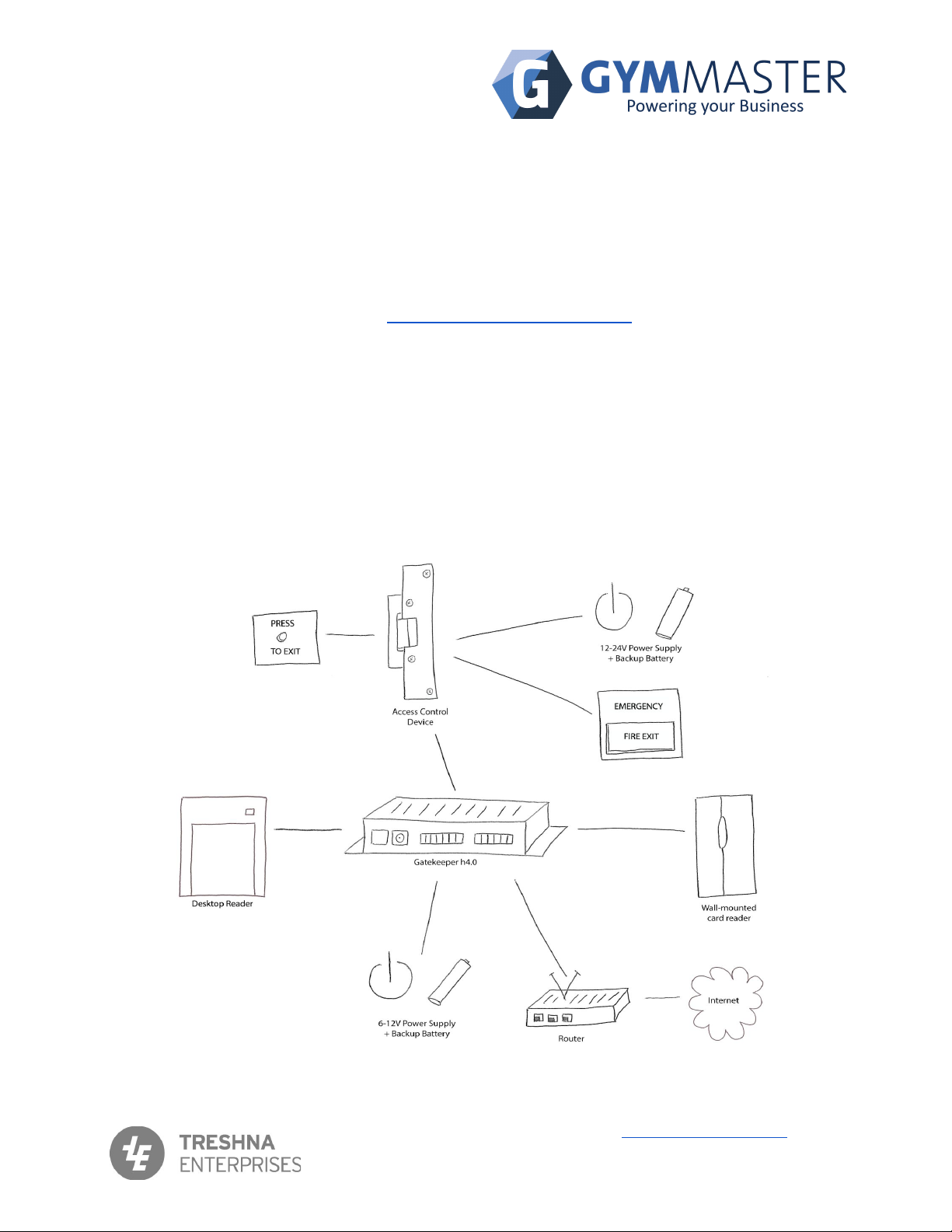
This guide includes an overview of the hardware involved, example wiring diagrams for both
Fail-Secure and Fail-Safe access control devices, emergency buttons, as well as diagnostic tests
and basic troubleshooting. A more comprehensive troubleshooting guide can be found on our
support page.
Please read this manual carefully before the installation of the GateKeeper and readers.
Hardware Checklist
❏GateKeeper computer
❏Power supply (basic unit provided)
You will also have one or more:
❏Desktop reader with Standard USB type A data cable
❏Wall-mounted card reader (with diodes, supplied with stub-wiring for bench testing)
You will also need the following items:
❏Internet Connection
❏Router or Network switch
❏Standard Network cable (Cat5) to connect the GateKeeper to router, network or switch
❏Uninterruptible Power Supply (UPS) to maintain constant power for the GateKeeper,
door readers, Internet router and all network components (Strongly recommended)
❏Additional door hardware as required (exit button, emergency exit, door lock, turnstile etc)
PLEASE NOTE: ADDITIONAL ITEMS ARE NOT SUPPLIED BY GYMMASTER.
❏DOOR LOCK SHOULD BE PREFERABLY 12V DC MAGNETIC LOCK OR ELECTRIC
STRIKE.
EPIC Sanctuary
78-106 Manchester St
Christchurch 8011
New Zealand
PO Box 13352
Armagh Mail Centre
Christchurch 8011
New Zealand
www.gymmastersoftware.com
NZ 03 974 9169
AU 03 9111 0323
US 415 678 1270
Page 2

GateKeeper Overview
The GateKeeper h4.2 contains both the GateKeeper computer and relay unit required to operate
the access control that works with GymMaster. The GateKeeper needs to be powered AND
connected to the Internet to work correctly. The GateKeeper can also be used to operate desktop
readers and receipt printers, which connect to the USB ports.
We strongly recommend that you use an Uninterruptible Power Supply (UPS) with line smoothing
to provide a constant power supply to the GateKeeper, Door Readers, Internet router and any
network components. Desktop PCs and other computer devices are high power-drain, and should
not be connected to the UPS. The UPS will assist in maintaining normal member access and
system operation in the event of a power failure or fluctuations.
You will need to check your own local and regional legal requirements for emergency entrance and
exit. It is strongly recommended that you install an Emergency Fire Exit Button and/or a general
Exit Button for members in your door setup, and that you have alternative and separate
key-lock access or similar.
EPIC Sanctuary
78-106 Manchester St
Christchurch 8011
New Zealand
PO Box 13352
Armagh Mail Centre
Christchurch 8011
New Zealand
www.gymmastersoftware.com
NZ 03 974 9169
AU 03 9111 0323
US 415 678 1270
Page 3

Power Supply
The GateKeeper requires a 12 power supply capable of at least 1000mA. The GateKeeper is
calibrated to work with input voltage from 9V to 12V. Do NOT use a power supply with voltage
greater than 12V or current lower than 1000mA. There are two power supply sockets that suit: (1) a
screw-terminal connector or (2) a 2.1x5.5mm barrel connector with the centre positive. You can
use the power supply shipped with the GateKeeper for the screw-terminal socket.
It is strongly recommended to use an Uninterruptible Power Supply (UPS) to maintain constant
power for the GateKeeper, door readers, Internet router and all network components.
Door lock MUST have its own separate power supply. Do NOT use the GateKeeper or
the GateKeeper power supply to power any mag locks or door strike.
If you have a maglock, your door reader MUST NOT be mounted on conductive metal
without an earth, or this may cause interference issues.
Note: Maximum length of RS232 serial cable connection is 15 metres (50 feet).
Maximum length of a standard USB cable connection is 3 metres (10 feet).
EPIC Sanctuary
78-106 Manchester St
Christchurch 8011
New Zealand
PO Box 13352
Armagh Mail Centre
Christchurch 8011
New Zealand
www.gymmastersoftware.com
NZ 03 974 9169
AU 03 9111 0323
US 415 678 1270
Page 4

GateKeeper Interface
Relay Terminals
These terminals are for signalling the access control device. For loads over 2A, we do not
recommend connecting directly. Use a secondary relay as a buffer instead.
NO Relay normally open contact
COM Relay common terminal
NC Relay normally closed contact
As access control devices are often inductive, switching off the current can cause a voltage spike
on the wires to the access control, damaging the reader. A snubber should be fitted near any
switch or relay contacts, for DC circuits a silicon rectifier diode such as IN4001 (supplied) is well
suited. Please note that the wire diode in the wrong direction (polarity) will cause a short circuit
and damage the power supply.
The diode MUST be wired correctly according to the diagram, otherwise it may cause
damage to the GateKeeper board or the device power supply.
EPIC Sanctuary
78-106 Manchester St
Christchurch 8011
New Zealand
PO Box 13352
Armagh Mail Centre
Christchurch 8011
New Zealand
www.gymmastersoftware.com
NZ 03 974 9169
AU 03 9111 0323
US 415 678 1270
Page 5

Exit Button Terminals
The GateKeeper expects a low level voltage trigger signal in the sensor terminal to activate the
relay to open the door. You can wire a normally-open push button (2 terminals) to Sensor and
GND on the Door 1 or Door 2 socket, refer to the sample wiring diagram.
You need to enable the push button sensor in the door setting page in GymMaster at Settings ->
Door and Readers -> [Specified Door].
RFID Reader Sockets
The rear of the GateKeeper has two sockets. Up to 2 door readers can be connected. Each reader
socket has 4 terminals for reader, namely Serial A, Serial B, +12V OUT, GND.
The RFID reader has a number of wires, but only 4 of them are used. The unused wires should be
insulated from the rest. The 4 wires that are used are coloured green, white, red and black. The
default connection relationships between the reader terminals and readers are:
Terminal
Wire Colour
A
Green
B
White
VCC
Red
GND
Black
The RFID reader must be mounted in a location where the electrical noise is quiet. If there is a lot
of electrical noise, read performance will be reduced. Electrical noise can be generated from the
usual source (motors, VSD’s, switch mode power supplies, CRT monitors, fluorescent lights etc).
New electrical equipment (if installed correctly) is usually ok, as it should already meet EMC
requirements.
If you have two door readers, they should be physically separated to avoid interfering with each
other.
Network Port
The GateKeeper requires an Internet connection via the Network port to function normally. You will
need a CAT5 or CAT6 Network cable (not supplied), one end connected to the Network port on the
EPIC Sanctuary
78-106 Manchester St
Christchurch 8011
New Zealand
PO Box 13352
Armagh Mail Centre
Christchurch 8011
New Zealand
www.gymmastersoftware.com
NZ 03 974 9169
AU 03 9111 0323
US 415 678 1270
Page 6

GateKeeper, the other end connected to an Network port on the router or a switch. Please ensure
Internet access for this connection.
The GateKeeper can operate for short periods in Offline Mode during a network outage, as long as
the GateKeeper, door lock components, and facility network components have electrical power. It
is strongly recommended to use an Uninterruptible Power Supply (UPS) to maintain constant
power for the GateKeeper, door readers, Internet router and all network components.
The GateKeeper network port has a green/amber LED at the top left corner, and an amber LED at
the top right corner. The left LED shows whether the cable is correctly inserted. The right LED
shows network activity. When powered and connected to the router, you would normally expect to
see a solid left LED and a flickering right LED, indicating correct connection and ongoing activity.
USB Ports
Desktop readers and receipt printers are connected by USB cable to one of the USB ports at the front
of the GateKeeper.
The Gatekeeper USB ports MUST be used ONLY for GymMaster devices. If you
attempt to connect or charge any electronic device, such as mobile phone, digital
camera, etc, this can cause reader faults.
EPIC Sanctuary
78-106 Manchester St
Christchurch 8011
New Zealand
PO Box 13352
Armagh Mail Centre
Christchurch 8011
New Zealand
www.gymmastersoftware.com
NZ 03 974 9169
AU 03 9111 0323
US 415 678 1270
Page 7

Sample Wiring Diagrams
These wiring diagrams are intended only as examples of how the relay unit and RFID device may
be installed. Actual installation wiring may differ. The GateKeeper is supplied with stub wiring so
that the system can be bench-tested. Typically, the GateKeeper will be positioned or mounted at or
near the facility reception desk. This enables the desktop reader to be connected, and door
readers to be connected by longer cabling fitted to wall and floor edges. This positioning also
typically allows the GateKeeper to use the same network cable access to the Internet router as
used by the reception computer.
Fail Secure locks will LOCK the door when the power goes off.
Fail Safe locks will leave the door UNLOCKED when the power goes off.
Check with your local fire regulations as to which you should use.
Door lock, door lock power supply, and any Push to Exit buttons are NOT supplied by GymMaster,
and should be sourced in advance by installer.
Note: If you use Fail Secure locks, it is STRONGLY recommended that you have
alternative means by which you can physically unlock the door in case of outage
(loss of power, or no connection to Internet for a long period, etc).
Door lock MUST have its own separate power supply. Do NOT use the GateKeeper or
the GateKeeper power supply to power any mag locks or door strike.
EPIC Sanctuary
78-106 Manchester St
Christchurch 8011
New Zealand
PO Box 13352
Armagh Mail Centre
Christchurch 8011
New Zealand
www.gymmastersoftware.com
NZ 03 974 9169
AU 03 9111 0323
US 415 678 1270
Page 8

Combinations of Relay Units
There are several useful ways in which multiple relay units can be interconnected. In these
illustrations, the data connections to the door reader and PC are not shown.
Bi-Directional
When you want to have readers both sides of the door, you need to combine the relay contacts.
These wiring patterns can be used in combination with the power supply sharing wiring pattern
above. The wiring pattern you should use depends on which relay contacts are being used.
Normally Open Contacts
In arrangements where the normally open (NO) contacts are used, wire the relays in parallel.
Change from this: To this:
Normally Closed Contacts
In arrangements where the normally closed (NC) contacts are used, wire the relays in series.
EPIC Sanctuary
78-106 Manchester St
Christchurch 8011
New Zealand
PO Box 13352
Armagh Mail Centre
Christchurch 8011
New Zealand
www.gymmastersoftware.com
NZ 03 974 9169
AU 03 9111 0323
US 415 678 1270
Page 13

GateKeeper Status
The front of the GateKeeper h4.2 makes it easy to diagnose whether there is a problem, and the
nature of any such problems.
What Do the Lights Mean?
Ref
Light
Activity
Indicates
1
Ser1 (or Act1)
Ser2 (or Act2)
Flickering/Off
Flickers when the GateKeeper is able to talk to
the attached readers
2
Network Port
Amber & Green On/Off
Network connection (both should be on)
3
Power
On/Off
Power to the GateKeeper unit
4
Error
Red/Off
There is an error
5
Reader 1
Reader 2
On/Off
Reader/s are connected
6
Database
On/Off
Connection to the cloud server
7
Internet
On/Off
Internet Connection
8
All OK
On/Off
Everything is working as it should be.
9
Relay
Flickering/Off
Should turn on when the door opens.
10
Not used
Not used
Not used
EPIC Sanctuary
78-106 Manchester St
Christchurch 8011
New Zealand
PO Box 13352
Armagh Mail Centre
Christchurch 8011
New Zealand
www.gymmastersoftware.com
NZ 03 974 9169
AU 03 9111 0323
US 415 678 1270
Page 14

Troubleshooting
Test the relay wiring to the magnet lock
Once you have finished the wiring, you should test if the wiring is correct and working by using a
paperclip. Do this before plugging the connector into the GateKeeper socket.
Find a paperclip, straighten it and then bend it as depicted below. Connect the paperclip into the
two holes where the two wires connect to the magnet lock. You should be able to see the door lock
activate or deactivate, depending on the type of lock.
EPIC Sanctuary
78-106 Manchester St
Christchurch 8011
New Zealand
PO Box 13352
Armagh Mail Centre
Christchurch 8011
New Zealand
www.gymmastersoftware.com
NZ 03 974 9169
AU 03 9111 0323
US 415 678 1270
Page 15

To demonstrate, if the lock mechanism is unengaged (unlocked) before you connect in the
paperclip, it should be engaged (locked) after you connect the paperclip.
If the lock is engaged (locked) before you plug in the paperclip, it should become unengaged
(unlocked) after the paperclip is connected.
If that does not happen, it means that the wiring has not been done correctly on the lock
mechanism. Please check power supply for the lock and other related wiring.
EPIC Sanctuary
78-106 Manchester St
Christchurch 8011
New Zealand
PO Box 13352
Armagh Mail Centre
Christchurch 8011
New Zealand
www.gymmastersoftware.com
NZ 03 974 9169
AU 03 9111 0323
US 415 678 1270
Page 16
Table of contents
Other Gym Master Gate Opener manuals