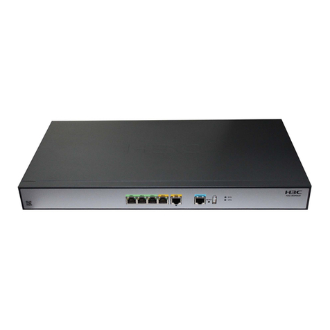
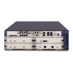
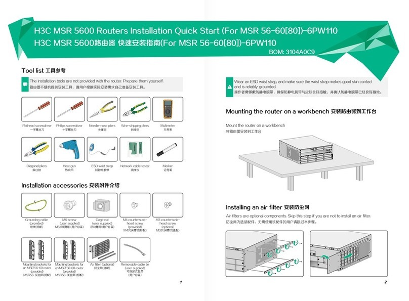
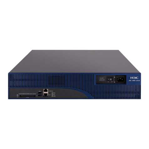
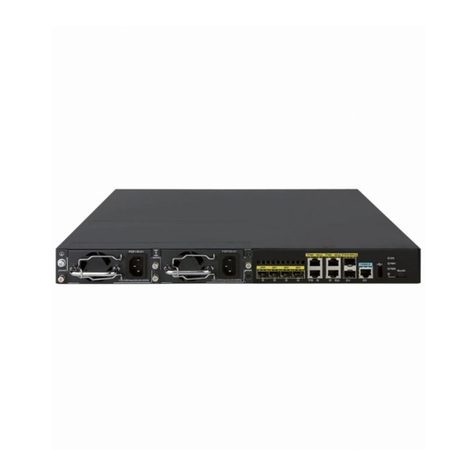
H3C MSR3600-28 User manual

i
Contents
Installing the router························································································1
Installation prerequisites ····································································································································1
Installation flow···················································································································································1
Installing the router·············································································································································3
Installing an air filter···································································································································3
Mounting the router on a workbench··········································································································3
Installing the router in a rack······················································································································4
Grounding the router········································································································································27
Grounding the router through the grounding terminal on the rack···························································27
Grounding the router with a grounding strip·····························································································29
Grounding the router with a grounding conductor buried in the earth ground··········································30
Installing an interface module ··························································································································30
Installing a SIC·········································································································································30
Installing a DSIC ······································································································································31
Installing an HMIM ···································································································································33
Installing a MIM········································································································································34
Connecting the router to the network···············································································································35
Connecting an Ethernet cable··················································································································35
Connecting an optical fiber·······················································································································36
Installing a CF card··········································································································································37
Installing a Micro SD card································································································································38
Installing an SSD drive·····································································································································39
Logging in through the console port·················································································································40
Connecting a console cable·····················································································································40
Setting terminal parameters·····················································································································43
Installing a power module ································································································································44
Connecting the power cord······························································································································46
Connecting an AC power cord·················································································································46
Connecting a DC power cord···················································································································48
Connecting an RPS power cord···············································································································50
Verifying the installation···································································································································51
Accessing the router for the first time···············································································································51

1
Installing the router
WARNING
!
To avoid injury, do not touch bare wires, terminals, or parts with high-voltage hazard signs.
IMPORTANT:
•
The barcode on the router chassis contains product information that must be provided to local
sales agent when you return a faulty router for service.
•
Keep the tamper-proof seal on a mounting screw on the chassis cover intact, and if you want to
open the chassis, contact H3C for permission. Otherwise, H3C shall not be liable for any
consequence.
Installation prerequisites
•
You have read "Preparing for installation" carefully.
•
All requirements in "Preparing for installation" are met.
Installation flow
You can install the router on a workbench or in a rack. Select an installation method according to the
installation environment, and follow the installation flowchart shown in Figure 1.

2
Figure 1 Installation flow
Yes
No
Ground the router
Install the interface
modules
Connect the interface
cables
Install the CF card
Connect the power cords
Verify the installation
Power on the router Troubleshoot the router
Power off the router
Operating correctly
End
Install the air filter
Install the Micro SD card
Install the power modules
Install the SSD hard disk
Connect the router to the
configuration terminal
Start
Mount the router on
a workbench Mount the router in
a rack
Install the router

3
Installing the router
Installing an air filter
No air filter is provided with the router. Purchase one yourself. Only the MSR 36-40 and MSR 36-60
support air filters.
To install an air filter:
1. Face the left side (side of the inlet vents) of the router.
2. Install the upper and lower guide rails of the air filter to the chassis. Fasten the fastening screws
on the guide rails with a Phillips screwdriver. See Figure 2.
Figure 2 Installing the upper and lower guide rails
3. Push the air filter along the guide rails from the rear side of the chassis to the front.
Figure 3 Pushing the air filter along the guide rails
Mounting the router on a workbench
IMPORTANT:
•
Ensure good ventilation and 100 mm (3.94 in) of clearance around the chassis for heat
dissipation.
•Do not place heavy objects on the router.
To mount the router on a workbench:

4
1. Make sure the workbench is clean, stable, and correctly grounded.
2. Place the router upside down on the workbench and attach the rubber feet to the four round
holes in the chassis bottom.
Figure 4 Attaching the rubber feet (MSR 36-10 AC)
3. Place the router on the workbench with the upside up.
Figure 5 Mounting the router on a workbench (MSR 36-10 AC)
Installing the router in a rack
Mounting brackets
The following routers require only the front mounting brackets:
•
MSR3600-28
•
MSR3600-28-SI
•
MSR3600-28-SI-GL
•
MSR3600-28-X1
•
MSR3600-28-X1-DP
•
MSR3600-51
•
MSR3600-51-SI
•
MSR3600-51-X1
•
MSR3600-51-X1-DP
The following routers require both the front and rear mounting brackets:
•
MSR 36-10
•
MSR 36-20
•
MSR3610-G

6
Router dimensions
Figure 8 MSR 36-10/36-20 router dimensions
480 mm (18.90 in)
60 mm
(2.36 in)
Front mounting
bracket
RPS power
cord
65 mm
(2.56 in)
E1 cable

7
Figure 9 MSR3610-G/3620-G router dimensions
470 mm
(18.50 in) 60 mm
(2.36 in)
45 mm
(1.77 in)
E1 cable
Power
cord

8
Figure 10 MSR3620-DP router dimensions
470 mm (18.50 in)
60 mm
(2.36 in)
Ethernet
network cable
45 mm
(1.77 in)
E1 cable
Front mounting
bracket

9
Figure 11 MSR 36-40/36-60 router dimensions
480 mm (18.90 in)
E1 cable
60 mm
(2.36 in)
Power cord
60 mm
(2.36 in)
Front mounting
bracket

10
Figure 12 MSR3600-28 router dimensions
360 mm (14.17 in)
60 mm
(2.36 in)
60 mm
(2.36 in)
E1 cable
Front mounting
bracket
Power cord

11
Figure 13 MSR3600-28-SI/3600-28-SI-GL router dimensions
360 mm (14.17 in)
60 mm
(2.36 in) 45 mm
(1.77 in)
Power cord
Ethernet
network cable
Front mounting
bracket

12
Figure 14 MSR3600-28-X1 router dimensions
360 mm (14.17 in)
60 mm
(2.36 in)
60 mm
(2.36 in)
Power cord
E1 cable
Front mounting
bracket

13
Figure 15 MSR3600-28-X1-DP router dimensions
360 mm (14.17 in)
60 mm
(2.36 in )
60 mm
(2.36 in)
Power cord
E1 cable
Front mounting
bracket

14
Figure 16 MSR3600-51 router dimensions
400 mm (15.75 in) 45 mm
(1.77 in)
60 mm
(2.36 in)
Front mounting
bracket
Power cord
Ethernet
network cable
E1 cable

15
Figure 17 MSR3600-51-SI router dimensions
360 mm (14.17 in)
60 mm
(2.36 in) 45 mm
(1.77 in)
Power
cord Ethernet
network cable
Front mounting
bracket

16
Figure 18 MSR3600-51-X1 router dimensions
400 mm (15.75 in)
60 mm
(2.36 in) 45 mm
(1.77 in)
Ethernet
network cable
Power cord
E1 cable
Front mounting
bracket

17
Figure 19 MSR3600-51-X1-DP router dimensions
To house the router, the rack must meet the requirements described in Table 1.
Table 1 Router dimensions and requirements for the rack
Router model
Dimensions
Requirements for the rack
MSR 36-10
•Height—44.2 mm (1.74 in), 1 RU
•Width—440 mm (17.32 in)
•Total depth—605 mm (23.82 in)
Chassis depth—480 mm
(18.90 in)
Space for connecting an
RPS power cord—65 mm
(2.56 in)
Space for connecting an E1
cable—60 mm (2.36 in)
•Depth—A minimum of 680 mm (26.77
in)
•Distance from the front post to the
front door—Aminimum of 80 mm (3.15
in)
•Distance from the front post to the
rear door—A minimum of 550 mm
(21.65 in)
•Distance from the front post to the
rear post
290 mm (11.42 in) to 430 mm (16.93
in)
Allow a minimum of 160 mm (6.30
in) distance from the rear post to the
rear door.
450 mm (17.72 in) to 610 mm (24.02
in)
MSR 36-20
•Height—44.2 mm (1.74 in), 1 RU
•Width—440 mm (17.32 in)
•Total depth—605 mm (23.82 in)
Chassis depth—480 mm
(18.90 in)
•Depth—A minimum of 680 mm (26.77
in)
•Distance from the front post to the
front door—Aminimum of 80 mm (3.15
in)
•Distance from the front post to the
400 mm (15.75 in)
60 mm
(2.36 in) 45 mm
(1.77 in)
Ethernet
network cable
Power cord
E1 cable
Front mounting
bracket

18
Router model
Dimensions
Requirements for the rack
Space for connecting an
RPS power cord—65 mm
(2.56 in)
Space for connecting an E1
cable—60 mm (2.36 in)
rear door—A minimum of 550 mm
(21.65 in)
•Distance from the front post to the
rear post
290 mm (11.42 in) to 430 mm (16.93
in)
Allow a minimum of 160 mm (6.30
in) distance from the rear post to the
rear door.
450 mm (17.72 in) to 610 mm (24.02
in)
MSR3610-G/MS
R3620-G
•Height—44.2 mm (1.74 in), 1 RU
•Width—440 mm (17.32 in)
•Total depth—575 mm (22.64 in)
Chassis depth—470 mm
(18.50 in)
Space for connecting an E1
cable—60 mm (2.36 in)
Space for connecting a
power cord—45 mm (1.77 in)
•Depth—A minimum of 680 mm (26.77
in)
•Distance from the front post to the
front door—Aminimum of 80 mm (3.15
in)
•Distance from the front post to the
rear door—A minimum of 550 mm
(21.65 in)
MSR3620-DP
•Height—44.2 mm (1.74 in), 1 RU
•Width—440 mm (17.32 in)
•Total depth—575 mm (22.64 in)
Chassis depth—470 mm
(18.50 in)
Space for connecting an
Ethernet cable—45 mm (1.77
in)
Space for connecting an E1
cable—60 mm (2.36 in)
•Depth—A minimum of 680 mm (26.77
in)
•Distance from the front post to the
front door—Aminimum of 70 mm (2.76
in)
•Distance from the front post to the
rear door—A minimum of 500 mm
(19.69 in)
•Distance from the front post to the
rear post—286 to 608 mm (11.26 to
23.94 in)
MSR 36-40
•Height—88.1 mm (3.47 in), 2 RU
•Width—440 mm (17.32 in)
•Total depth—600 mm (23.62 in)
Chassis depth—480 mm
(18.90 in)
Space for connecting an E1
cable—60 mm (2.36 in)
Space for connecting a
power cord—60 mm (2.36 in)
•Depth—A minimum of 680 mm (26.77
in)
•Distance from the front post to the
front door—Aminimum of 80 mm (3.15
in)
•Distance from the front post to the
rear door—A minimum of 550 mm
(21.65 in)
•Distance from the front post to the
rear post
310 mm (12.20 in) to 440 mm (17.32
in)
Allow a minimum of 160 mm (6.30
in) distance from the rear post to the
rear door.
465 mm (18.31 in) to 595 mm (23.43
in)
(As a best practice, use a rack shelf to mount
the router in a rack.)
MSR 36-60
•Height—135 mm (5.32 in), 3 RU
•Width—440 mm (17.32 in)
•Total depth—600 mm (23.62 in)
Chassis depth—480 mm
(18.90 in)
Space for connecting an E1
•Depth—A minimum of 680 mm (26.77
in)
•Distance from the front post to the
front door—Aminimum of 80 mm (3.15
in)
•Distance from the front post to the
rear door—A minimum of 550 mm

19
Router model
Dimensions
Requirements for the rack
cable—60 mm (2.36 in)
Space for connecting a
power cord—60 mm (2.36 in)
(21.65 in)
•Distance from the front post to the
rear post
310 mm (12.20 in) to 440 mm (17.32
in)
Allow a minimum of 160 mm (6.30
in) distance from the rear post to the
rear door.
465 mm (18.31 in) to 595 mm (23.43
in)
(As a best practice, use a rack shelf to mount
the router in a rack.)
MSR3600-28
•Height—44.2 mm (1.74 in), 1 RU
•Width—440 mm (17.32 in)
•Total depth—480 mm (18.90 in)
Chassis depth—360 mm
(14.17 in)
Space for connecting an AC
power cord—60 mm (2.36 in)
Space for connecting an E1
cable—60 mm (2.36 in)
•Depth—A minimum of 600 mm (23.62
in)
•Distance from the front post to the
front door—A minimum of 80 mm (3.15
in)
•Distance from the front post to the
rear door—A minimum of 420 mm
(16.54 in)
MSR3600-28-SI/
MSR3600-28-SI-
GL
•Height—43.6 mm (1.72 in), 1 RU
•Width—440 mm (17.32 in)
•Total depth—465 mm (18.31 in)
Chassis depth—360 mm
(14.17 in)
Space for connecting an AC
power cord—60 mm (2.36 in)
Space for connecting an
Ethernet cable—45 mm (1.77
in)
•Depth—A minimum of 600 mm (23.62
in)
•Distance from the front post to the
front door—Aminimum of 80 mm (3.15
in)
•Distance from the front post to the
rear door—A minimum of 420 mm
(16.54 in)
MSR3600-28-X1/
MSR3600-28-X1-
DP
•Height—43.6 mm (1.72 in), 1 RU
•Width—440 mm (17.32 in)
•Total depth—480 mm (18.90 in)
Chassis depth—360 mm
(14.17 in)
Space for connecting an AC
power cord—60 mm (2.36 in)
•Space for connecting an
Ethernet cable—60 mm (2.36 in)
•Depth—A minimum of 600 mm (23.62
in)
•Distance from the front post to the
front door—Aminimum of 80 mm (3.15
in)
•Distance from the front post to the
rear door—A minimum of 420 mm
(16.54 in)
MSR3600-51
•Height—44.2 mm (1.74 in), 1 RU
•Width—440 mm (17.32 in)
•Total depth—505 mm (19.88 in)
Chassis depth—400 mm
(15.75 in)
Space for connecting an
Ethernet cable—45 mm (1.77
in)
Space for connecting an E1
cable—60 mm (2.36 in)
•Depth—A minimum of 600 mm (23.62
in)
•Distance from the front post to the
front door—Aminimum of 80 mm (3.15
in)
•Distance from the front post to the
rear door—A minimum of 460 mm
(18.11 in)
MSR3600-51-SI
•Height—43.6 mm (1.72 in), 1 RU
•Width—440 mm (17.32 in)
•Total depth—465 mm (18.31 in)
Chassis depth—360 mm
•Depth—A minimum of 600 mm (23.62
in)
•Distance from the front post to the
front door—Aminimum of 80 mm (3.15
in)
This manual suits for next models
15
Table of contents
Other H3C Network Router manuals

H3C
H3C H3C S5600 Series User manual

H3C
H3C S3100-52P User manual

H3C
H3C S3100-52P User manual

H3C
H3C SR6616 User manual

H3C
H3C RA5100 User manual

H3C
H3C s5820x series User manual

H3C
H3C S5120-HI Series Instruction Manual

H3C
H3C MSR810 Installation manual

H3C
H3C CR16000-F User manual

H3C
H3C S3100-52P User manual

H3C
H3C MSR 5600 Installation manual

H3C
H3C SR6600 SPE-FWM Installation manual

H3C
H3C S3100-52P User manual

H3C
H3C H3C S5600 Series User manual

H3C
H3C S12500R Series Quick guide

H3C
H3C AR 18-22-24 User manual

H3C
H3C S3600V2 SERIES User manual

H3C
H3C MSR 5600 User manual

H3C
H3C MSR-20-21 ROUTER User manual

H3C
H3C CR16000-M User manual