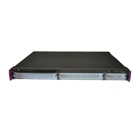
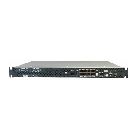
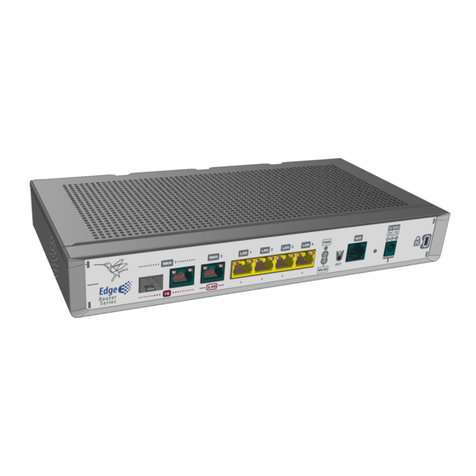
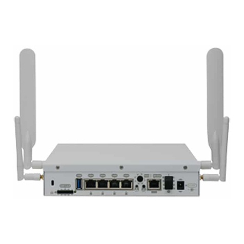
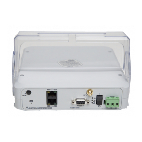
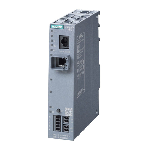
Teldat H2 RAIL User manual

Teldat H2 RAIL
Installation Manual
Copyright© Teldat DM685-I Version 1.4 11/2016 Teldat S.A.
Teldat S.A. Manual
Teldat H2 RAIL 1

Legal Notice
Warranty
This publication is subject to change.
Teldat S.A. offers no warranty whatsoever for information contained in this manual.
Teldat S.A. is not liable for any direct, indirect, collateral, consequential or any other damage connected to the deliv-
ery, supply or use of this manual.
Manual Teldat S.A.
2Teldat H2 RAIL

Table of Contents
Chapter1 Aboutthismanual ................................. 1
1.1 Supporteddevices................................... 1
1.2 Who should read this manual? . . . . . . . . . . . . . . . . . . . . . . . . . . . . . . 1
1.3 When should this manual be read? . . . . . . . . . . . . . . . . . . . . . . . . . . . . 1
1.4 Whatisinthismanual?................................. 1
1.5 Whatisnotinthismanual? ............................... 1
1.6 How is the information organized? . . . . . . . . . . . . . . . . . . . . . . . . . . . . 1
1.7 Technicalsupport.................................... 1
1.8 Relateddocumentation................................. 2
Chapter2 TeldatH2Rail.................................... 3
2.1 Introduction...................................... 3
2.1.1 Powersupply ..................................... 3
2.1.2 Hardwaremonitoring.................................. 3
Chapter 3 Components and power supply . . . . . . . . . . . . . . . . . . . . . . . . . . 4
3.1 Components...................................... 4
3.1.1 Frontpanel ...................................... 4
3.1.2 Rearpanel....................................... 5
3.2 Mountingoptions.................................... 5
3.2.1 Assembly: Recommendations . . . . . . . . . . . . . . . . . . . . . . . . . . . . . . 6
3.2.2 Outlinedrawing..................................... 6
3.3 Powersource ..................................... 7
3.3.1 Connecting the power supply. . . . . . . . . . . . . . . . . . . . . . . . . . . . . . . 7
3.4 RESETButton..................................... 8
3.4.1 Rebootingthedevice.................................. 8
3.4.2 Defaultconfiguration.................................. 9
3.5 Connectingthedata................................... 9
3.5.1 Dataconnection.................................... 9
3.5.2 Connecting to a WWAN antenna . . . . . . . . . . . . . . . . . . . . . . . . . . . . 10
3.5.3 Connecting the WLAN antenna . . . . . . . . . . . . . . . . . . . . . . . . . . . . . 12
3.5.4 Connecting the GPS antenna . . . . . . . . . . . . . . . . . . . . . . . . . . . . . 12
3.5.5 Configuration connection . . . . . . . . . . . . . . . . . . . . . . . . . . . . . . . 12
3.6 SIMcardinstallation ................................. 14
3.6.1 InstallingtheSIM................................... 14
Teldat S.A. Table of Contents
Teldat H2 RAIL i

Chapter4 Compliance.................................... 16
4.1 Manufacturerinformation ............................... 16
4.2 Safetywarnings ................................... 16
4.3 WEEEinformation.................................. 18
4.4 REACH....................................... 18
4.5 EC declaration of conformity . . . . . . . . . . . . . . . . . . . . . . . . . . . . . . 18
4.6 Nationalrestrictions.................................. 19
4.7 Operatingfrequency ................................. 19
4.7.1 WWANAntenna................................... 19
4.7.2 WLANantenna.................................... 19
4.8 Labeling....................................... 19
Appendix A Technical information. . . . . . . . . . . . . . . . . . . . . . . . . . . . . . . 21
A.1 Troubleshooting................................... 21
A.2 Maintenance..................................... 21
A.2.1 Softwareupdates................................... 21
A.3 Connectors ..................................... 21
A.3.1 POWERconnector.................................. 21
A.3.2 LANconnector.................................... 22
A.3.3 WWANconnectors.................................. 22
A.3.4 WLANconnectors .................................. 22
A.3.5 GPSconnector.................................... 23
A.3.6 Configurationconnector................................ 23
A.4 Technicalspecifications................................ 23
AppendixB Radioinformation................................. 27
B.1 RFspecifications................................... 27
B.2 WI-FIspecifications.................................. 28
Table of Contents Teldat S.A.
ii Teldat H2 RAIL

Chapter 1 About this manual
This is the installation manual for the Teldat H2 RAIL router. It contains instructions on how to install the device in a
working environment.
1.1 Supported devices
The information in this manual only applies to the Teldat H2 RAIL router.
1.2 Who should read this manual?
This manual should be read by support personnel who need to install, configure, maintain and monitor the device.
1.3 When should this manual be read?
Read this guide as soon as you are ready to familiarize yourself with the device and its components.
This manual will help you understand your new device and all of its capabilities.
1.4 What is in this manual?
This installation guide contains the following:
• A description of the features available on the Teldat H2 RAIL router.
• A description of the technical specifications.
• A detailed description of the power supply requirements.
• A description of the LEDs and connectors on the device.
• Troubleshooting information.
1.5 What is not in this manual?
This manual does not cover device software and configuration. To find out how to configure the device, please read
the relevant protocol manuals to be found in http://www.teldat.com.
1.6 How is the information organized?
Each chapter focuses on a specific hardware part and its components. All information (technical specifications, de-
scriptive information, etc.) relating to a particular component can be found in the chapter dedicated to said compon-
ent.
1.7 Technical support
Teldat S.A. offers a technical support service. Regular firmware upgrades are available for maintenance purposes
and additional features.
Contact information:
Web: http://www.teldat.com
Tel. Nº: +34 918 076 565
Fax: +34 918 076 566
Teldat S.A. 1 About this manual
Teldat H2 RAIL 1

Email: suppor[email protected]
1.8 Related documentation
Teldat Dm748-I Software Updating.
Teldat Dm781-I Cellular Interface.
Teldat Dm812-I GPS.
Note
The manufacturer reserves the right to make changes and/or improvements to any and all parts of the
software and hardware of this product, and to modify the specifications of this manual without prior no-
tice.
The images depicting the device's front and rear panels are for information purposes only. The actual
device may be slightly different.
1 About this manual Teldat S.A.
2Teldat H2 RAIL

Chapter 2 Teldat H2 Rail
2.1 Introduction
This manual shows you how to install and connect the Teldat H2 RAIL router.
Fig. 1: Teldat H2 RAIL: Outer features
2.1.1 Power supply
For further information on the Teldat H2 RAIL power supply, please see Connecting the power supply on page 7.
2.1.2 Hardware monitoring
The LEDs on the front panel are used to monitor the hardware in the Teldat H2 RAIL. These LEDs provide visual in-
formation regarding the state of the hardware components, indicating whether there is connectivity, data flow, etc.
For further information on said LED panel, please see LEDs on page 5.
Teldat S.A. 2 Teldat H2 Rail
Teldat H2 RAIL 3

Chapter 3 Components and power supply
This chapter provides information on the chassis and components of the Teldat H2 RAIL. Said information covers
the following:
• Components.
• Assembly instructions.
• Power supply.
• RESET button.
• Data connection.
• SIM card installation.
3.1 Components
3.1.1 Front panel
The following image shows the front panel of the device.
Fig. 2: Front panel
The elements on the front panel are described in the following table:
Table 1: Front panel elements
Item Description
POWER Power connection. For further information on the power connection, please see Power
source on page 7
MOD1, MOD2 WWAN antenna connectors.
The interfaces created are cellular1/x and cellular2/x, respectively.
The type of device installed for each position depends on the commercial configuration.
GPS GPS antenna connector.
MOD3, MOD4 WWAN/WLAN antenna connectors.
The interface created is cellular3/x, or wlan3/0, for MOD 3 and cellular4/x, or wlan4/0, for
MOD4.
The type of device installed for each position depends on the commercial configuration.
LAN1..LAN4 LAN connector.
AUX DB9 connector, which provides access to the device local console for configuration and
monitoring purposes.
RESET Reset button. For further information on how the reset button operates, please see RESET
Button on page 8
In addition to the connectors, the front panel also contains a set of LEDs, which provides information on the status of
the router.
3 Components and power supply Teldat S.A.
4Teldat H2 RAIL

3.1.1.1 LEDs
The following image shows the location of the front panel LEDs:
Fig. 3: Teldat H2 RAIL: Front panel
The meaning of each LED depends on the modules installed. Each LED belongs to one of four possible modules.
The following table describes what each LED means:
WWAN module Off -> system stopped.
Red -> interface is unavailable because it is being installed, it isn't enabled
(shutdown), or due to an auto-test failure.
Amber -> idle.
• Rapid blinking. The device has not registered with the network or does not have
enough quality to do so.
• Slow blinking. GSM connection (GPRS).
• Steady. WCDMA (UMTS / HSDPA) connection.
Green -> connected. Blinking: connection data activity.
WLAN module Red -> interface down.
Green -> interface up.
Blinking (green/red) -> activity/maintenance.
3.1.2 Rear panel
The following image shows the Teldat H2 RAIL rear panel, where you can see the rest of the connectors.
Fig. 4: Rear panel
The elements on the rear panel are as follows:
Table 3: Rear panel elements
Item Description
SIM card 1..4 SIM trays
Each SIM is assigned to its WWAN module. If, however, the device only has one WWAN module installed, said mod-
ule can handle both SIM 1 and SIM 2 (DualSim Option).
3.2 Mounting options
The Teldat H2 RAIL is designed to be installed in a 19-inch rack.
Teldat S.A. 3 Components and power supply
Teldat H2 RAIL 5

Note
The equipment is intended to be both handled and installed by qualified service personnel. If not, the
device may be damaged and malfunction.
There are two brackets, with slots attached to the front panel, to hold the device firmly in place.
3.2.1 Assembly: Recommendations
Insert the router into a 19-inch rack and align the brackets in the rack.
We recommend securing the unit to the rack using the screws and nuts provided. This will ensure the device is se-
curely mounted.
Fig. 5: Mounting screws
3.2.2 Outline drawing
The following outline drawing provides installation instructions:
3 Components and power supply Teldat S.A.
6Teldat H2 RAIL

Fig. 6: Outline drawing
3.3 Power source
Note
Please read the following instructions carefully before connecting the router!
3.3.1 Connecting the power supply
The Teldat H2 RAIL is powered by a 110 V or 24 V nominal DC power source depending on the model.
Note
Please verify device power input is valid for your power feeding.
There is no on/off switch or fuse. A label on the rear of the equipment contains the power supply information.
To comply with electrical safety regulations, this equipment must be connected to
the vehicle power network through a 1 amp approved thermo-magnetic circuit
breaker (ABB-S281-UC-K-1 or equivalent).
The H2 Rail has one earth terminal (on the rear panel). It must be grounded
through a cable with a section measuring, at least, 2 mm 2(AWG14).
This equipment must be grounded. Never defeat the ground conductor or operate
the equipment in the absence of a suitably installed ground conductor. Contact the
appropriate electrical inspection authority or an electrician if you are uncertain that
suitable grounding is available. When installing or replacing the unit, the ground
connection must always be established first and disconnected last.
The following image shows the location of the power connector.
Fig. 7: Power supply connection
3.3.1.1 Power connector pins
The power connector on this router is an M12 4-pole code Amale connector or equivalent.
PIN Signal M12 4P Code A male
Teldat S.A. 3 Components and power supply
Teldat H2 RAIL 7

1 + V DC
2 + V DC
3 0 V
4 0 V
Note
Connections 1-2 and 3-4 are redundant. We recommend keeping this redundancy to guarantee device
availability.
3.3.1.2 Power cable
The power cable is not supplied with the router. The estimated maximum consumption for this equipment is 150 mA
operating at 110 VDC or 830mA operating at 24 VDC. Any cable with a cable gauge greater than, or equal to, 0.2
mm2(AWG24) is acceptable. The type of cable and its gauge, however, will be determined by the characteristics of
the female connector used.
For example, for a female Phoenix Contact SACC-M12FS-4CON-PG7-M or equivalent, we recommend using a
cable with an outside diameter of 4-6 mm with four AWG24-AWG18 conductors.
You do not need a shielded cable but, if you do intend to use one, we recommend you attach the cable to the
grounding point on the other side of the router, to the ground point on the power supply or to both.
Electric current in power cables, telephone lines and communication cables is
dangerous. To prevent electric shocks, before installing, handling or opening the
equipment covers, connect and disconnect the cables as shown in the following
table:
To connect To disconnect
Make sure the power supply cable is not connected to
the device.
Disconnect the power supply cable from the power sup-
ply.
Connect all data cables. Disconnect the power supply cable from the device.
Connect the power supply cable to the device. Disconnect the data cables.
Connect the power supply cable to the power supply.
3.4 RESET Button
The following sections describe the features for the RESET button.
3.4.1 Rebooting the device
Once the device is operating normally, press the RESET button to reboot.
3 Components and power supply Teldat S.A.
8Teldat H2 RAIL

3.4.2 Default configuration
The RESET button allows you to reset your router to its default configuration. If you want execute reset, carry out the
following steps:
• With the device switched off, press and hold the RESET button down while you turn the router on using the ON/
OFF switch (1).
• The PSU LED (green) will light up and the LED Slot begins to blink (amber). This continues to blink for 10 seconds.
• To reboot the device with the default configuration, let go of the RESET button while the LED Slot is still blinking
(i.e., before the 10-second period expires).
The default configuration sets up the device with the following IP address and access mask:
• IP address: 192.168.1.1
• IP mask: 255.255.255.0
Note
Some devices leave the factory with customized settings. This personalization may mean your router
default configuration is different from the one shown above.
3.5 Connecting the data
The Teldat H2 RAIL has the following data connections.
3.5.1 Data connection
The Teldat H2 RAIL is equipped with the following data connectors:
3.5.1.1 LAN SWITCH
The Teldat H2 RAIL incorporates a 4-port 10/100/1000BaseT switch with automatic MDI/MDIX support to connect to
a local area network (LAN).
The router has a LINK LED to indicate connection status.
Fig. 8: LAN Switch ports (4)
3.5.1.1.1 LAN connector pins
The LAN connector installed in the router is an M12 8P X-Code female connector or equivalent.
PIN GE Signal -> Signal M12 8P X-Code female connector
1 BI-DA+ ->Tx+ (1)
2 BI-DA- -> Tx- (2)
3 BI-DB+ -> Rx+ (3)
Teldat S.A. 3 Components and power supply
Teldat H2 RAIL 9

4 BI-DB--> Rx- (6)
5 BI-DD+ (4)
6 BI-DD- (5)
7 BI-DC-(7)
8 BI-DC+(8)
Note
The switch's automatic MDIX feature means you can use a pin-to-pin cable to connect to another
device without having to cross the Tx-Rx pairs.
3.5.1.2 AUX
The front panel of the Teldat H2 RAIL contains a DB9 female connector marked AUX, which can be used as a
router configuration port or as a V.24 asynchronous serial port (via a configuration command). The interface behavior
or functionality must be pre-configured. By default, it is configured as a configuration port. This section focuses on
how to make the connector work in asynchronous port mode.
The interface allows you to connect asynchronous serial devices, which can operate without hardware control sig-
nals. This makes it possible, for example, to connect external modems or an an asynchronous PPP WAN.
Another interesting feature of the port is it can be used as a GPS data source in NMEA sentences (GPS-DATA).
The interface is a V.24-compliant interface. It cannot control hardware flow as it only has data signals and not control
signals. It does, however, allow for software flow control (XON/XOFF).
Parity cannot be configured in MARK and SPACE modes.
To set parity, you need to connect the AUX port to an asynchronous terminal (or to a PC with terminal emulation).
For information on how to use the port as a router configuration port, please see the section on LAN connector pins
on page 9
Fig. 9: AUX port
Teldat Dm812-I GPS.
3.5.2 Connecting to a WWAN antenna
The Teldat H2 RAIL has up to eight type N connectors for connecting WWAN antennas.
Name WWAN Module Antenna Function
MOD1 1 MD1 Main
MOD1 2 MD1 Aux. / diversity
MOD2 1 MD2 Main
MOD2 2 MD2 Aux. / diversity
MOD3 1 MD3 Main
3 Components and power supply Teldat S.A.
10 Teldat H2 RAIL

MOD3 2 MD3 Aux. / diversity
MOD4 1 MD4 Main
MOD4 2 MD4 Aux. / diversity
The router does not have any internal antennas. Antennas must be installed in the Teldat H2 RAIL to improve the
quality of the signal received and transmitted by the Wireless WAN module (GPRS, UMTS, HSDPA, HSUPA,
HSPA+, LTE, etc.).
The cable used to connect the antennas must be valid for radio frequency (RF) signal communications of up to 2.6
GHz frequencies and with 50 Ohm impedance. Please note the quality and length (loss) of an antenna cable can af-
fect the quality of the RF signals transmitted and received. This, in turn, will affect the device coverage and data ex-
change rates.
Note
An appropriate software license must be installed for the WWAN interface to work.
Each router module is equipped with two WWAN antenna connectors (1and 2).
Depending on the technology used, you can either use one antenna (e.g., for GPRS connection) or both (e.g., for
LTE).
Installing an antenna in the Main (1) connector is mandatory. The second connector (2, Ext.Diversity) may not be
needed. If you don't need the second one, disable the antenna (through configuration) for optimum performance.
If you install both the Main and Ext Diversity antennas, they must be separated by a minimum of 7 cm. The maximum
recommended distance is 25 cm.
For optimum performance, please use the radio frequency accessories (antennas and cables) recommended by
Teldat.
The following image shows the location of the WWAN antenna connectors.
Fig. 10: WWAN antenna connectors
3.5.2.1 Positioning the antenna
Antenna placement with respect to other wireless devices or other radiation sources (such as communication
devices, personal computers, etc.) can significantly influence device performance.
The antennas transmit and receive radio signals. Performance is also affected by environmental factors (such as the
distance between a device and a base station), physical obstacles and other radio frequency (RF) interference
sources.
For optimum coverage, carry out the following instructions:
• Whenever possible, place the antenna away from physical obstacles. Obstacles between the antenna and the
base station degrade the wireless signal. Place the antenna above ground level facing the nearest base station.
• Antennas are also affected by material density. Place them away from walls, metal screens, mirrors, etc.
• Do not place the antenna near columns, which may throw shadows thus reducing the coverage area.
• Keep the antenna away from metal pipes such as conduits, air-conditioning, etc.
• Please bear in mind that other wireless devices (such as telephones, microwaves, etc.) can temporarily interfere
with the quality of the wireless signal.
• Installing antennas in racks alongside communication devices, computers, etc., is not recommended. Use an ex-
tension cable and place the antenna outside.
Teldat S.A. 3 Components and power supply
Teldat H2 RAIL 11

The following recommendations are applicable to all wireless devices:
• Do not touch or move the antenna while the device is transmitting or receiving.
• Do not touch any equipment containing radiating devices if the antenna is very close to, or touching, any part of the
body (particularly the face and eyes) and is transmitting.
• Do not install the device in areas where the atmosphere is potentially explosive.
• Wireless devices can cause interference in other devices. Do not use them in areas where medical equipment is
installed.
3.5.3 Connecting the WLAN antenna
The Teldat H2 RAIL is equipped with type N connectors to connect up to two WLAN (Wi-Fi) antennas (on models
equipped with this interface).
Since the router doesn't have any internal antennas, external antennas must be installed on the Teldat H2 RAIL to
improve WLAN signal quality.
The cable used to connect the antennas must be valid for RF signal communications of up to 2.4 GHz (5.7 GHz for
802.11a) frequencies and impedances of 50 Ohm. Please note, the quality and length of an antenna cable can affect
the quality of RF signals transmitted and received. This, in turn, will affect the device coverage and data exchange
rates.
Please note an appropriate software license must be installed for the WWAN interface to work.
The following image shows the location of the WLAN antenna connectors (MOD3 and MOD4).
Fig. 11: WLAN antenna connectors
3.5.4 Connecting the GPS antenna
The Teldat H2 RAIL has an FME connector to connect an active GPS antenna (on models equipped with this inter-
face).
Since the router doesn't have any internal antennas, an active 3.3V external antenna must be installed on the Teldat
H2 RAIL to optimize the GPS signal quality.
The cable used to connect the antennas must be valid for radio frequency (RF) signal communications of up to 1.5
GHz frequencies and impedances of 50 Ohm. Please note the quality and length of an antenna cable can affect the
quality of the RF signals transmitted and received. This, in turn, will affect the device coverage and data exchange
rates.
The following image shows the location of the GPS antenna connector.
Fig. 12: GPS antenna connector
3.5.5 Configuration connection
3 Components and power supply Teldat S.A.
12 Teldat H2 RAIL

3.5.5.1 Configuration using the local console (AUX connector)

The Teldat H2 RAIL has a DB9 female connector on the front panel known as AUX. This provides access to the
router local console and can operate as an asynchronous serial port. The interface behavior, or function, must be
pre-configured. By default, it is configured in local console mode. This section focuses on the connection for local
console mode.
To configure local console mode, connect the AUX port to an asynchronous terminal (or to a PC with terminal emula-
tion).
Note
The terminal must be configured as follows:
- Speed: 9600 bps.
- Eight data bits.
- One stop bit.
- No parity bit.
- No flow control.
Connection to the configuration port is carried out using a DB9 male and a DB9 female connector. If the terminal has
DB25 connectors, you will need an additional adapter.
Fig. 13: Connection for configuration
3.5.5.2 Configuration using the IP terminal (LAN1..4 connectors)
The Teldat H2 RAIL includes a default configuration, which activates if the device has not been pre-configured.
The router default configuration sets up the device with the following IP access address and mask:
• IP Address: 192.168.1.1
• IP Mask: 255.255.255.0
Note
Some devices leave the factory with customized settings. This personalization may mean your router
default configuration is different from the one shown above.
This initial configuration lets you access the router configuration console through the Telnet IP protocol. To do this,
carry out the following:
Teldat S.A. 3 Components and power supply
Teldat H2 RAIL 13

• Configure the Ethernet interface on the IP terminal (usually a PC) using an IP address within the following range
[192.168.1.2, 192.168.1.254] and mask 255.255.255.0. For example, 192.168.1.2, 255.255.255.0.
• Connect the IP terminal Ethernet interface to any of the Ethernet switch ports on the Teldat H2 RAIL (LAN1..4
connectors) using an appropriate Ethernet cable (M12 to RJ45).
• Start a Telnet session from the IP terminal to IP address 192.168.1.1 ( Teldat H2 RAIL default address).
• The default configuration does not ask for login credentials (user/password) to access the console.
For further information on how to configure the device, please refer to the user manuals provided by Teldat on the
documentation CD or on the web.
3.6 SIM card installation
The Teldat H2 RAIL is equipped with up to four WWAN interfaces that require SIM cards to operate.
Some carriers in certain countries provide services (CDMA), which do not require SIM cards. However, in routers
where a SIM card is required, at least one must be inserted.
The Teldat H2 RAIL has four SIM trays located on the rear of the device.
Where the router is equipped with four modules, a SIM tray is automatically assigned to each module.
When only one cellular module is installed, a SIM card should be inserted in SIM tray 1, 2, or both.
Warning
This router is compatible with 1.8 V and 3 V SIM cards. Do not install SIMs that do not support these
voltages.
Never install a SIM card when the device is switched on.
Always disconnect the router from the main power supply before installing a SIM card.
Always disconnect the device before removing the casing to access the trays.
Protect yourself against electrostatic discharges (ESD) when inserting a SIM card.
Do not touch the SIM card connectors.
3.6.1 Installing the SIM
To insert a SIM card into a SIM tray, first place the router with the rear panel facing towards you (as shown in the fol-
lowing figure) on a stable surface and then follow the instructions given below:
Fig. 14: SIM trays
(1) Press the button until the SIM tray slides out of the slot.
(2) Place the SIM card on the tray.
(3) Return the tray into the slot by pushing it in.
3 Components and power supply Teldat S.A.
14 Teldat H2 RAIL

Fig. 15: Inserting the SIMs
Teldat S.A. 3 Components and power supply
Teldat H2 RAIL 15

Chapter 4 Compliance
4.1 Manufacturer information
Brand Teldat
Manufacturer Teldat S.A.
Country Spain
Postal Address Isaac Newton 10, Parque Tecnologico de Madrid,28760 Tres Cantos, Madrid,
Spain
International Phone +34 91 807 65 65
4.2 Safety warnings
Hazardous voltage. Danger to life! Do not open this equipment when it is switched
on.
Voltaje peligroso. ¡Peligro de muerte!
No abra este equipo cuando esté conectado a la corriente.
This equipment must be grounded. Never defeat the ground conductor or operate
the equipment in the absence of a suitably installed ground conductor. Contact the
appropriate electrical inspection authority or an electrician if you are uncertain
whether suitable grounding is available. When installing or replacing the unit, the
ground connection must always be made first and disconnected last.
Este equipo debe ser conectado a tierra. Nunca abandone la toma de tierra u
opere el equipo en ausencia de una toma de tierra adecuada. Contacte con la
autoridad eléctrica apropiada o con un electricista si tiene dudas sobre la situación
de su toma de tierra. Cuando instale o reemplace el equipo, se debe conectar la
conexión de tierra primero y desconectarla la última.
This equipment has been designed to work with an extended ambient temperature
range of up to 70 °C (158 °F) and under these conditions the metallic surface
could reach dangerous temperatures that may cause injuries.
Este equipo ha sido diseñado para funcionar con una temperatura ambiente de
rango extendido de hasta 70 ºC (158 ºF) y bajo estas condiciones la superficie
metálica puede alcanzar temperaturas que puden causar daños.
The equipment is intended to be installed by service personnel and only handled
by qualified personnel. If not, the device may be damaged and malfunction.
4 Compliance Teldat S.A.
16 Teldat H2 RAIL
Other manuals for H2 RAIL
2
Table of contents
Other Teldat Network Router manuals

Teldat
Teldat H1 RAIL Series User manual

Teldat
Teldat C+ Series User manual

Teldat
Teldat H2 RAIL User manual

Teldat
Teldat Connect-FW User manual

Teldat
Teldat SDE User manual

Teldat
Teldat ATLAS 150 User manual

Teldat
Teldat K Seres User manual

Teldat
Teldat Teldat-3Ge-USB User manual

Teldat
Teldat Connect 104KF TLDPM00A1 User manual

Teldat
Teldat G1N User manual

Teldat
Teldat C1+L User manual

Teldat
Teldat 3ge User manual

Teldat
Teldat M2 User manual

Teldat
Teldat Connect-104 User manual

Teldat
Teldat RS123 Seies User manual

Teldat
Teldat M2 User manual

Teldat
Teldat M1 User manual

Teldat
Teldat Teldat-3Ge User manual

Teldat
Teldat Connect-FW5G User manual

Teldat
Teldat ATLAS 60 NW User manual