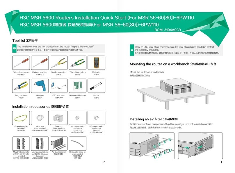
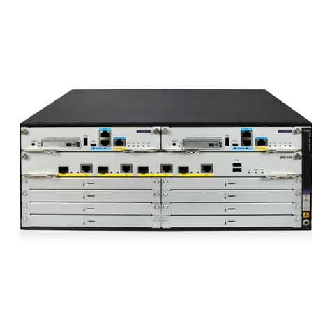
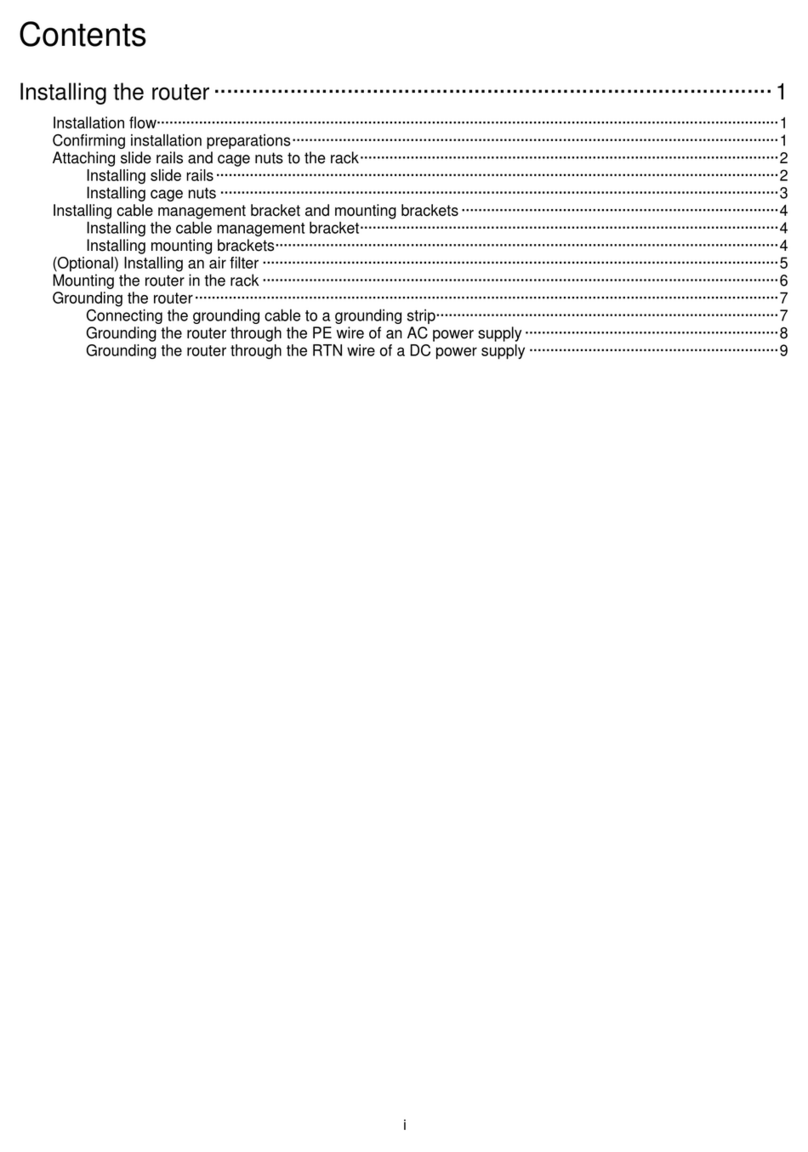
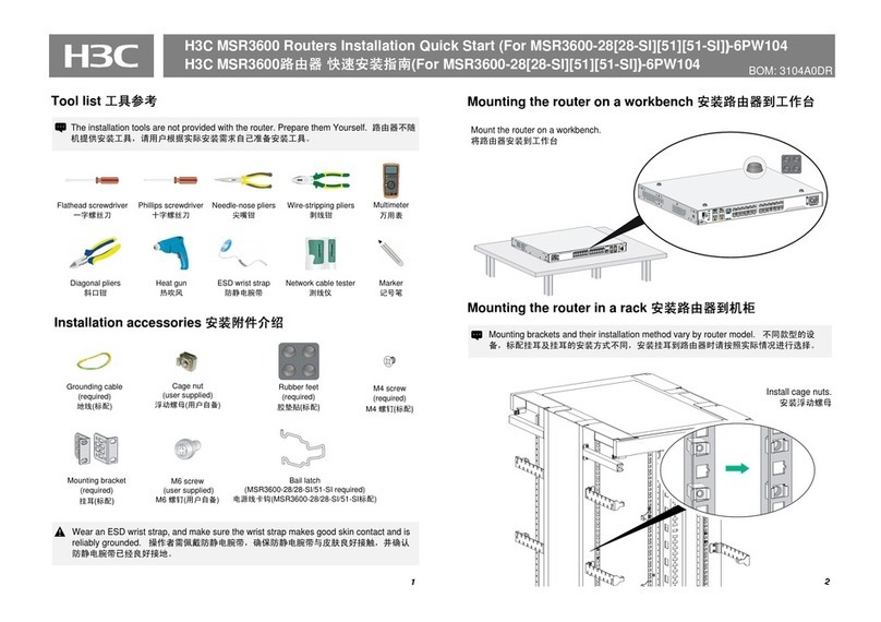
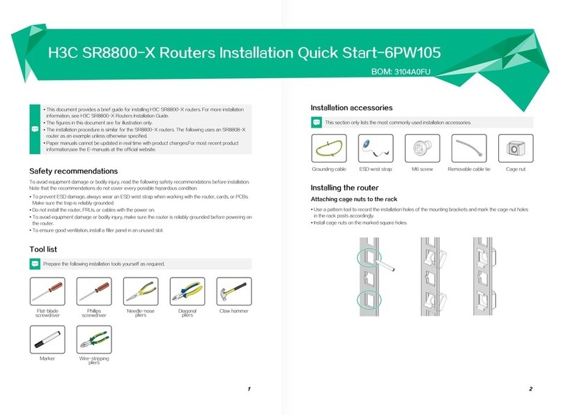
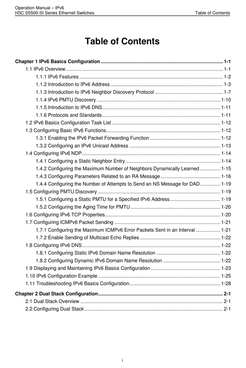
H3C MSR 5600 User manual

H3C MSR 5600 Routers
Comware 7 Virtual Technologies
Configuration Guide
New H3C Technologies Co., Ltd.
http://www.h3c.com
Software version: MSR-CMW710-R0809
Document version: 6W400-20200823

Copyright © 2020, New H3C Technologies Co., Ltd. and its licensors
All rights reserved
No part of this manual may be reproduced or transmitted in any form or by any means without prior written
consent of New H3C Technologies Co., Ltd.
Trademarks
Except for the trademarks of New H3C Technologies Co., Ltd., any trademarks that may be mentioned in this
document are the property of their respective owners.
Notice
The information in this document is subject to change without notice. All contents in this document, including
statements, information, and recommendations, are believed to be accurate, but they are presented without
warranty of any kind, express or implied. H3C shall not be liable for technical or editorial errors or omissions
contained herein.

Preface
This configuration guide describes the IRF features.
This preface includes the following topics about the documentation:
•
Audience.
•
Conventions.
•
Documentation feedback.
Audience
This documentation is intended for:
•
Network planners.
•
Field technical support and servicing engineers.
•
Network administrators.
Conventions
The following information describes the conventions used in the documentation.
Command conventions
Convention
Description
Boldface Bold text represents commands and keywords that you enter literally as shown.
Italic Italic text represents arguments that you replace with actual values.
[ ] Square brackets enclose syntax choices (keywords or arguments) that are optional.
{ x | y | ... }
Braces enclose a set of required syntax choices separated by vertical bars, from which
you select one.
[ x | y | ... ]
Square brackets enclose a set of optional syntax choices separated by vertical bars,
from which you select one or none.
{ x | y | ... } *
Asterisk marked braces enclose a set of required syntax choices separated by vertical
bars, from which you select a minimum of one.
[ x | y | ... ] *
Asterisk marked square brackets enclose optional syntax choices separated by vertical
bars, from which you select one choice, multiple choices, or none.
&<1-n> The argument or keyword and argument combination before the ampersand (&) sign
can be entered 1 to n times.
# A line that starts with a pound (#) sign is comments.
GUI conventions
Convention
Description
Boldface Window names, button names, field names, and menu items are in Boldface. For
example, the New User window opens; click OK.
> Multi-level menus are separated by angle brackets. For example, File > Create >
Folder.

Symbols
Convention
Description
WARNING! An alert that calls attention to important information that if not understood or followed
can result in personal injury.
CAUTION:
An alert that calls attention to important information that if not understood or followed
can result in data loss, data corruption, or damage to hardware or software.
IMPORTANT:
An alert that calls attention to essential information.
NOTE:
An alert that contains additional or supplementary information.
TIP:
An alert that provides helpful information.
Network topology icons
Convention
Description
Represents a generic network device, such as a router, switch, or firewall.
Represents a routing-capable device, such as a router or Layer 3 switch.
Represents a generic switch, such as a Layer 2 or Layer 3 switch, or a router that
supports Layer 2 forwarding and other Layer 2 features.
Represents an access controller, a unified wired-WLAN module, or the access
controller engine on a unified wired-WLAN switch.
Represents an access point.
Represents a wireless terminator unit.
Represents a wireless terminator.
Represents a mesh access point.
Represents omnidirectional signals.
Represents directional signals.
Represents a security product, such as a firewall, UTM, multiservice security
gateway, or load balancing device.
Represents a security module, such as a firewall, load balancing, NetStream, SSL
VPN, IPS, or ACG module.
Examples provided in this document
Examples in this document might use devices that differ from your device in hardware model,
configuration, or software version. It is normal that the port numbers, sample output, screenshots,
and other information in the examples differ from what you have on your device.
T
T
T
T

Documentation feedback
We appreciate your comments.

i
Contents
Configuring an IRF fabric···············································································1
About IRF···························································································································································1
IRF network model·····································································································································1
IRF benefits················································································································································2
Basic concepts···········································································································································3
IRF network topology·································································································································5
Master election···········································································································································5
Interface naming conventions····················································································································6
File system naming conventions················································································································6
Configuration synchronization····················································································································7
Multi-active handling procedure·················································································································7
MAD mechanisms······································································································································9
Restrictions and guidelines: IRF configuration·································································································12
Hardware compatibility with IRF···············································································································12
Software requirements for IRF·················································································································12
IRF fabric size··········································································································································12
Candidate IRF physical interfaces ···········································································································12
Transceiver modules and cables selection for IRF··················································································13
IRF port connection··································································································································13
IRF physical interface configuration restrictions and guidelines ······························································13
Feature compatibility and configuration restrictions with IRF···································································14
Licensing requirements for IRF················································································································14
Configuration rollback restrictions············································································································14
IRF tasks at a glance·······································································································································15
Planning the IRF fabric setup···························································································································16
Setting up an IRF fabric ···································································································································16
Assigning a member ID to each IRF member device···············································································16
Specifying a priority for each member device··························································································16
Binding physical interfaces to IRF ports···································································································17
Saving configuration to the next-startup configuration file ·······································································17
Connecting IRF physical interfaces··········································································································17
Setting the operating mode to IRF mode·································································································17
Accessing the IRF fabric··························································································································18
Configuring MAD··············································································································································19
Restrictions and guidelines for MAD configuration ··················································································19
Configuring LACP MAD ···························································································································19
Configuring BFD MAD······························································································································20
Excluding interfaces from the shutdown action upon detection of multi-active collision··························24
Recovering an IRF fabric ·························································································································24
Optimizing IRF settings for an IRF fabric·········································································································25
Changing the member ID of a member device ························································································25
Changing the priority of a member device ·······························································································25
Adding physical interfaces to an IRF port ································································································26
Bulk-configuring basic IRF settings for a member device········································································27
Enabling IRF auto-merge·························································································································28
Configuring a member device description································································································28
Configuring the IRF bridge MAC address································································································28
Enabling software auto-update for software image synchronization························································29
Setting the IRF link down report delay·····································································································30
Removing an expansion interface card that has IRF physical interfaces·················································30
Replacing an expansion interface card that has IRF physical interfaces·················································31
Display and maintenance commands for IRF··································································································31
IRF configuration examples ·····························································································································31
Example: Configuring an LACP MAD-enabled two-chassis IRF fabric····················································31
Example: Configuring a BFD MAD-enabled two-chassis IRF fabric························································34
Example: Restoring standalone mode·····································································································37
ii

1
Configuring an IRF fabric
About IRF
The Intelligent Resilient Framework (IRF) technology virtualizes multiple physical devices at the
same layer into one virtual fabric to provide data center class availability and scalability. IRF
virtualization technology offers processing power, interaction, unified management, and
uninterrupted maintenance of multiple devices.
IRF network model
Figure 1 shows an IRF fabric that has two devices, which appear as a single node to the upper-layer
and lower-layer devices.
Figure 1 IRF application scenario
As shown in Figure 2, Device A and Device B form a two-chassis IRF fabric. The fabric has four
MPUs (one active and three standbys), and two times the number of interface cards that a single
device provides. The IRF fabric manages the physical and software resources of Device A and
Device B in a centralized manner.
IP network
IRF fabric
IP network
IRF link Simplified to
Master Subordinate

2
Figure 2 Two-chassis IRF fabric implementation schematic diagram
IRF benefits
IRF provides the following benefits:
•
Simplified topology and easy management—An IRF fabric appears as one node and is
accessible at a single IP address on the network. You can use this IP address to log in at any
member device to manage all the members of the IRF fabric. In addition, you do not need to run
the spanning tree feature among the IRF members.
•
1:N redundancy—In an IRF fabric, one member acts as the master to manage and control the
entire IRF fabric. All the other members process services while backing up the master. When
the master fails, all the other member devices elect a new master from among them to take over
without interrupting services.
•
IRF link aggregation—You can assign several physical links between neighboring members
to their IRF ports to create a load-balanced aggregate IRF connection with redundancy.
•
Multichassis link aggregation—You can use the Ethernet link aggregation feature to
aggregate the physical links between the IRF fabric and its upstream or downstream devices
across the IRF members.
•
Network scalability and resiliency—Processing capacity of an IRF fabric equals the total
processing capacities of all the members. You can increase ports, network bandwidth, and
processing capacity of an IRF fabric simply by adding member devices without changing the
network topology.
IRF link
An IRF
fabric is
formed.
Master
(Member ID=1)
Subordinate
(Member ID=2)
Active MPU
Device A
(Member ID=1) Device B
(Member ID=2)
IRF physical
interfaces IRF physical
interfaces
IRF-port 2 IRF-port 1
Network
interfaces
Network
interfaces
IRF
Standby MPU
Active MPU
Standby MPU
IRF’s master MPU
IRF’s standby MPU
IRF’s standby MPU
IRF’s standby MPU

3
Basic concepts
Operating mode
The device operates in one of the following modes:
•
Standalone mode—The device cannot form an IRF fabric with other devices.
•
IRF mode—The device can form an IRF fabric with other devices.
IRF member roles
IRF uses two member roles: master and standby (called subordinate throughout the
documentation).
When devices form an IRF fabric, they elect a master to manage and control the IRF fabric, and all
the other devices back up the master. When the master device fails, the other devices automatically
elect a new master. For more information about master election, see "Master election."
IRF member ID
An IRF fabric uses member IDs to uniquely identify and manage its members. This member ID
information is included as the first part of interface numbers and file paths to uniquely identify
interfaces and files in an IRF fabric. Two devices cannot form an IRF fabric if they use the same
member ID. Adevice cannot join an IRF fabric if its member ID has been used in the fabric.
MPU roles
Each IRF member device has one or two MPUs. The following are MPU roles:
Role Description
Master MPU Active MPU of the master device. It is also called the global active MPU. You
configure and manage the entire IRF fabric at the CLI of the global active
MPU.
Active MPU
Active MPU on each member device. An active MPU performs the following
tasks:
•Manages the local device, including synchronizing configuration with the
local standby MPU, processing protocol packets, and creating and
maintaining route entries.
•Processes IRF-related events, such as master election and topology
collection.
Standby MPU
For the master MPU, all other MPUs are standby MPUs, including active
MPUs on subordinate devices.
If a member device has two MPUs, the MPU backing up the local active MPU
is the local standby MPU from the perspective of the member device.
Member priority
Member priority determines the possibility of a member device to be elected the master. A member
with higher priority is more likely to be elected the master.
IRF port
An IRF port is a logical interface that connects IRF member devices. Every IRF-capable device has
two IRF ports.
In standalone mode, the IRF ports are named IRF-port 1 and IRF-port 2.
In IRF mode, the IRF ports are named IRF-port n/1 and IRF-port n/2, where nis the member ID of the
device. The two IRF ports are referred to as IRF-port 1 and IRF-port 2.

4
To use an IRF port, you must bind a minimum of one physical interface to it. The physical interfaces
assigned to an IRF port automatically form an aggregate IRF link. An IRF port goes down when all its
IRF physical interfaces are down.
IRF physical interface
IRF physical interfaces connect IRF member devices and must be bound to an IRF port. They
forward traffic between member devices, including IRF protocol packets and data packets that must
travel across IRF member devices.
IRF split
IRF split occurs when an IRF fabric breaks up into multiple IRF fabrics because of IRF link failures,
as shown in Figure 3. The split IRF fabrics operate with the same IP address. IRF split causes
routing and forwarding problems on the network. To quickly detect a multi-active collision, configure
a minimum of one MAD mechanism (see "Configuring MAD").
Figure 3 IRF split
IRF merge
IRF merge occurs when two split IRF fabrics reunite or when two independent IRF fabrics are united,
as shown in Figure 4.
Figure 4 IRF merge
MAD
An IRF link failure causes an IRF fabric to split in two IRF fabrics operating with the same Layer 3
settings, including the same IP address. To avoid IP address collision and network problems, IRF
uses multi-active detection (MAD) mechanisms to detect the presence of multiple identical IRF
fabrics, handle collisions, and recover from faults.
IRF domain ID
One IRF fabric forms one IRF domain. IRF uses IRF domain IDs to uniquely identify IRF fabrics and
prevent IRF fabrics from interfering with one another.
As shown in Figure 5, IRF fabric 1 contains Device Aand Device B, and IRF fabric 2 contains Device
C and Device D. Both fabrics use the LACP aggregate links between them for MAD. When a
member device receives an extended LACPDU for MAD, it checks the domain ID to determine
whether the packet is from the local IRF fabric. Then, the member device can handle the packet
correctly.
=
IRF link
Device A Device B
IRF fabric
Device A Device B
IRF fabric 1 IRF fabric 2
+
IRF link
Device A Device B
Device A Device B
IRF fabric 1 IRF fabric 2 IRF fabric
+=

5
Figure 5 A network that contains two IRF domains
IRF network topology
An IRF fabric can use a daisy-chain topology, as shown in Figure 6.
IMPORTANT:
No relay devices are allowed between IRF member devices.
Figure 6 Daisy-chain topology
Master election
Master election occurs each time the IRF fabric topology changes in the following situations:
•
The IRF fabric is established.
•
The master device fails or is removed.
Device A Device B
IRF fabric 1
(domain 10)
IRF link
Core network
IRF fabric 2
(domain 20)
IRF link
Device C Device D
Access network
IRF
fabric
Master
Subordinate
IRF-port 2
IRF-port 1

6
•
The IRF fabric splits.
•
Independent IRF fabrics merge.
NOTE:
Master election does not occur
when split IRF fabrics merge. For information about the master
device of the merged IRF fabric, see "Failure recovery."
Master election selects a master in descending order:
1. Current master, even if a new member has higher priority.
When an IRF fabric is being formed, all members consider themselves as the master. This rule
is skipped.
2. Member with higher priority.
3. Member with the longest system uptime.
Two members are considered to start up at the same time if the difference between their startup
times is equal to or less than 10 minutes. For these members, the next tiebreaker applies.
4. Member with the lowest CPU MAC address.
For the setup of a new IRF fabric, the subordinate devices must reboot to complete the setup after
the master election.
For an IRF merge, devices must reboot if they are in the IRF fabric that fails the master election.
Interface naming conventions
In standalone mode:
A physical interface is numbered in the slot-number/subslot-number/interface-index format.
For example, set the link type of GigabitEthernet 1/0/1 to trunk, as follows:
<Sysname> system-view
[Sysname] interface gigabitethernet 1/0/1
[Sysname-GigabitEthernet1/0/1] port link-type trunk
In IRF mode:
Aphysical interface is numbered in the chassis-number/slot-number/subslot-number/interface-index
format. The chassis-number argument represents the IRF member ID.
For example, GigabitEthernet 1/2/0/1 represents the first port in slot 2 on member device 1. Set its
link type to trunk, as follows:
<Sysname> system-view
[Sysname] interface gigabitethernet 1/2/0/1
[Sysname-GigabitEthernet1/2/0/1] port link-type trunk
File system naming conventions
In standalone mode, you can use the storage device name to access the file system of the active
MPU. To access the file system of the standby MPU, use the name in the
slotslot-number#storage-device-name format.
On a multichassis IRF fabric, you can use the storage device name to access the file system of the
global active MPU. To access the file system of a global standby MPU, use the name in the
chassismember-ID#slotslot-number#storage-device-name format.
For more information about storage device naming conventions, see Fundamentals Configuration
Guide.

7
For example:
•
To create and access the test folder under the root directory of the flash memory on the global
active MPU:
<Master> mkdir test
Creating directory flash:/test... Done.
<Master> cd test
<Master> dir
Directory of flash:/test
The directory is empty.
524288 KB total (29832 KB free)
•
To create and access the test folder under the root directory of the flash memory in slot 0 on
member device 1:
<Master> mkdir chassis1#slot0#flash:/test
Creating directory chassis1#slot0#flash:/test... Done.
<Master> cd chassis1#slot0#flash:/test
<Master> dir
Directory of chassis1#slot0#flash:/test
The directory is empty.
524288 KB total (128812 KB free)
Configuration synchronization
IRF uses a strict running-configuration synchronization mechanism. In an IRF fabric, all MPUs obtain
and run the running configuration of the global active MPU. Configuration changes are automatically
propagated from the global active MPU to the remaining MPUs. The configuration files of these
MPUs are retained, but the files do not take effect. The subordinate devices use their own startup
configuration files on their respective local active MPU only after these devices are removed from the
IRF fabric.
As a best practice, back up the next-startup configuration file on a device before adding the device to
an IRF fabric as a subordinate.
A subordinate device's next-startup configuration file might be overwritten if the master and the
subordinate use the same file name for their next-startup configuration files. You can use the backup
file to restore the original configuration after removing the subordinate from the IRF fabric.
For more information about configuration management, see Fundamentals Configuration Guide.
Multi-active handling procedure
The multi-active handling procedure includes detection, collision handling, and failure recovery.
Detection
IRF provides MAD mechanisms by extending LACP and BFD to detect multi-active collisions. As a
best practice, configure a minimum of one MAD mechanism on an IRF fabric. For more information
about the MAD mechanisms and their application scenarios, see "MAD mechanisms."
For information about LACP, see Ethernet link aggregation in Layer 2—LAN Switching Configuration
Guide. For information about BFD, see High Availability Configuration Guide.

8
Collision handling
When MAD detects a multi-active collision, it sets all IRF fabrics except one to the Recovery state.
The fabric that is not placed in Recovery state can continue to forward traffic. The Recovery-state
IRF fabrics are inactive and cannot forward traffic.
LACP MAD and BFD MAD use the following process to handle a multi-active collision:
1. Compare the number of members in each fabric.
2. Set all fabrics to the Recovery state except the one that has the most members.
3. Compare the member IDs of the masters if all IRF fabrics have the same number of members.
4. Set all fabrics to the Recovery state except the one that has the lowest numbered master.
5. Shut down all common network interfaces in the Recovery-state fabrics except for the following
interfaces:
Interfaces automatically excluded from being shut down by the system.
Interfaces specified by using the mad exclude interface command.
Failure recovery
To merge two split IRF fabrics, first repair the failed IRF link and remove the IRF link failure.
After the failed IRF link between two split IRF fabrics is recovered, log in to the inactive IRF fabric to
reboot its member devices if the system requires you to do so. After these member devices join the
active IRF fabric as subordinate devices, the IRF merge is complete, as shown in Figure 7. The
network interfaces that have been shut down by MAD automatically restore their original state.
CAUTION:
If you
inadvertently reboot the active IRF fabric after the failed IRF link recovers,
its member devices
will join the inactive IRF fabric with their network interfaces being shut down by MAD. To
restore the
original states of the network interfaces in the merged IRF fabric, use the mad restore command.
NOTE:
If
the IRF auto-merge feature is enabled, the inactive IRF member devices will automatically reboot
after the failed IRF link recovers and a manual reboot is typically not required.
Figure 7 Recovering the IRF fabric
If the active IRF fabric fails before the IRF link is recovered (see Figure 8), use the mad restore
command on the inactive IRF fabric to recover the inactive IRF fabric. This command brings up all
network interfaces that were shut down by MAD. After the IRF link is repaired, merge the two parts
into a unified IRF fabric.
IRF
fabric
IP network
IP network
IRF fabric 1
(Active) IRF fabric 2
(Recovery)
IP network
IP network
IRF fabric 1
(Active) IRF fabric 2
(Recovery)
IP network
IP network
After the IRF
link is
recovered IRF merge

9
Figure 8 Active IRF fabric fails before the IRF link is recovered
MAD mechanisms
IRF provides MAD mechanisms by extending LACP and BFD.
Table 1 compares the MAD mechanisms and their application scenarios.
Table 1 Comparison of MAD mechanisms
MAD
mechanism Advantages Disadvantages Application
scenarios
LACP MAD
•Detection speed is fast.
•Runs on existing
aggregate links without
requiring MAD-dedicated
physical links or Layer 3
interfaces.
Requires an intermediate
device that supports
extended LACP for MAD.
Link aggregation is used
between the IRF fabric
and its upstream or
downstream device.
BFD MAD
•Detection speed is fast.
•Intermediate device, if
used, can come from any
vendor.
Requires MAD dedicated
physical links and Layer 3
interfaces, which cannot be
used for transmitting user
traffic. The MSR routers
support Layer 3 aggregate
interfaces for BFD MAD and
the interfaces must operate
in static aggregation mode.
•No special
requirements for
network scenarios.
•If no intermediate
device is used, this
mechanism is only
suitable for IRF
fabrics that have
only two members
IRF
fabric 1
(Active)
IRF fabric 2
(Recovery)
IP network
IP network
IRF fabric 2
(Recovery)
IP network
IP network
IRF fabric 1
fails before
the IRF link
is recovered.
IRF fabric 1
fails
because of
physical
problems
IRF fabric 2
(Active)
IP network
IP network
IRF fabric 1
fails
because of
physical
problems
IRF
fabric
IP network
IP network
Repair the
IRF link and
IRF fabric 1,
and finish
IRF merge
Execute the mad
restore command
on IRF fabric 2

10
MAD
mechanism Advantages Disadvantages Application
scenarios
that are
geographically
close to one
another.
LACP MAD
As shown in Figure 9, LACP MAD has the following requirements:
•
Every IRF member must have a link with an intermediate device.
•
All the links form a dynamic link aggregation group.
•
The intermediate device must be a device that supports extended LACP for MAD.
The IRF member devices send extended LACPDUs that convey a domain ID and an active ID (the
member ID of the master). The intermediate device transparently forwards the extended LACPDUs
received from one member device to all the other member devices.
•
If the domain IDs and active IDs sent by all the member devices are the same, the IRF fabric is
integrated.
•
If the extended LACPDUs convey the same domain ID but different active IDs, a split has
occurred. LACP MAD handles this situation as described in "Collision handling."
Figure 9 LACP MAD scenario
BFD MAD
BFD MAD detects multi-active collisions by using BFD.
Intermediate device
Master Subordinate
IRF
fabric
Internet
Customer
premise
network
IRF link
Common traffic path
LACP MAD traffic path
LACP-enabled dynamic
link aggregation
LACP-enabled dynamic
link aggregation

11
You can use common or management Ethernet ports for BFD MAD.
If management Ethernet ports are used, BFD MAD has the following requirements:
•
An intermediate device is required and each IRF member device must have a BFD MAD link to
the intermediate device.
•
Each member device is assigned a MAD IP address on the master's management Ethernet
port.
If common Ethernet ports are used, BFD MAD has the following requirements:
•
If an intermediate device is used, each member device must have a BFD MAD link to the
intermediate device. If no intermediate device is used, all member devices must have a BFD
MAD link to each other. As a best practice, use an intermediate device to connect IRF member
devices if the IRF fabric has more than two member devices. Afull mesh of IRF members might
cause broadcast loops.
•
Ports on BFD MAD links are assigned to a VLAN (or Layer 3 aggregate interface) used for BFD
MAD. Each member device is assigned a MAD IP address on the VLAN interface (or Layer 3
aggregate interface).
The BFD MAD links and BFD MAD VLAN (or Layer 3 aggregate interface) must be dedicated. Do not
use BFD MAD links or BFD MAD VLAN (or Layer 3 aggregate interface) for any other purposes.
When you use a Layer 3 aggregate interface for BFD MAD, make sure its member ports do not
exceed the maximum number of Selected ports allowed for an aggregation group. If the number of
member ports exceeds the maximum number of Selected ports, some member ports cannot become
Selected. BFD MAD will be unable to work correctly and its state will change to Faulty. For more
information about setting the maximum number of Selected ports for an aggregation group, see
Ethernet link aggregation in Layer 2—LAN Switching Configuration Guide.
NOTE:
•
The MAD addresses identify the member devices and must belong to the same subnet.
•
Of all management Ethernet ports on an IRF fabric, only the master's management Ethernet port is
accessible.
Figure 10 shows a typical BFD MAD scenario that uses an intermediate device. On the intermediate
device, assign the ports on the BFD MAD links to the same VLAN.
Figure 11 shows a typical BFD MAD scenario that does not use an intermediate device.
With BFD MAD, the master attempts to establish BFD sessions with other member devices by using
its MAD IP address as the source IP address.
•
If the IRF fabric is integrated, only the MAD IP address of the master takes effect. The master
cannot establish a BFD session with any other member. If you execute the display bfd
session command, the state of the BFD sessions is Down.
•
When the IRF fabric splits, the IP addresses of the masters in the split IRF fabrics take effect.
The masters can establish a BFD session. If you execute the display bfd session
command, the state of the BFD session between the two devices is Up.

12
Figure 10 BFD MAD scenario with an intermediate device
Figure 11 BFD MAD scenario without an intermediate device
Restrictions and guidelines: IRF configuration
Hardware compatibility with IRF
To form an IRF fabric, the MSR routers must be the same model and use the same type of MPU and
SPUs.
Voice or FCM modules cannot operate in IRF mode.
If you install a SIC-CNDE module on one IRF member device, you must install SIC-CNDE modules
on all other member devices.
Software requirements for IRF
All IRF member devices must run the same software image version. Make sure the software
auto-update feature is enabled on all member devices.
IRF fabric size
An IRF fabric can contain a maximum of two member devices.
Candidate IRF physical interfaces
Typically, use high-speed ports as IRF physical interfaces. You can use the following physical
interfaces for IRF links:
•
SPU100/200/300—All fixed GE ports.
Device
Master Subordinate
IRF fabric
IRF link
BFD MAD link
192.168.1.2/24 192.168.1.3/24
BFD MAD link
Master Subordinate
IRF fabric
IRF link
BFD MAD link
VLAN 2
192.168.1.2/24 VLAN 2
192.168.1.3/24

13
•
SPU100-X1—The six lowest numbered GE ports.
•
SPU200-X1/400-X1—All 10-GE ports and the lowest numbered GE port.
On some devices, specific physical interfaces have been assigned to the IRF port by default. You
cannot modify or configure IRF port bindings. On some devices, you must assign physical interfaces
to IRF ports from the CLI.
Transceiver modules and cables selection for IRF
When you select transceiver modules and cables, follow these restrictions and guidelines:
•
Use straight-through or crossover copper Ethernet cables to connect copper Ethernet ports for
a short-distance connection.
•
Use transceiver modules and fibers to connect fiber Ethernet ports for a long-distance
connection.
•
The transceiver modules at the two ends of an IRF link must be the same type.
Support for transceiver modules and cables varies by device model.
For more information about the transceiver modules and DAC cables, see the switch installation
guide and H3C Transceiver Modules User Guide.
NOTE:
The
transceiver modules and DAC cables available for the switch are subject to change over time.
For the most up
-to-date list of transceiver modules and DAC cables, contact your H3C sales
representative.
IRF port connection
When you connect two neighboring IRF members, follow these restrictions and guidelines:
•
You must connect the physical interfaces of IRF-port 1 on one member to the physical
interfaces of IRF-port 2 on the other.
•
For high availability, bind multiple physical interfaces to an IRF port. You can bind a maximum of
two physical interfaces to an IRF port.
Figure 12 Connecting IRF physical interfaces
IRF physical interface configuration restrictions and
guidelines
Command configuration restrictions
On a physical interface bound to an IRF port, you can execute only the following commands:
•
Interface commands, including the description and shutdown commands.
IRF-port 1IRF-port 2
IRF fabric
Other manuals for MSR 5600
5
Table of contents
Other H3C Network Router manuals

H3C
H3C S5500-EI series User manual

H3C
H3C S3100-52P Installation instructions

H3C
H3C RA5300 User manual

H3C
H3C MSR 900 Series User manual

H3C
H3C CR16000-M User manual

H3C
H3C SR6608 Operating and maintenance manual

H3C
H3C MSR810 Installation manual

H3C
H3C S3100-52P User manual

H3C
H3C SR6604 User manual

H3C
H3C MSR810 User manual

H3C
H3C HIM-8FE User manual

H3C
H3C S3100-52P User manual

H3C
H3C MSR 930 User manual

H3C
H3C MSR600 Series User manual

H3C
H3C SecPath M9000-S NSQM2MPUD0 User manual

H3C
H3C CR19000-16 User manual

H3C
H3C S9500 Series Installation instructions

H3C
H3C MSR 5600 Installation manual

H3C
H3C MSR3600-28 User manual

H3C
H3C MSR810 Installation manual