Haes Haescomm HC228-S Guide

Page 1 of 21
Haescomm HC228-S EVCS
Master Station
Installation and Commissioning Manual
Version 1 May 2022

Page 2 of 21
Table of Contents
1. Introduction 3
1.1 What is an Emergency Voice Communication System? 3
1.2 Suitability 3
2. Product Overview 3
3. Important Safety Information 4
4. Unpacking the Unit 5
5. Installation 6
5.1 Connecting the HC-228S Master Station 7
5.2 Planning the Wiring 7
5.3 Cable and Wiring Guidance 7
5.3.1 Fire Telephone system 7
5.3.2 Disabled Refuge EVC System 7
5.3.3 Combined Systems 7
5.3.4 “Assist Call” Emergency Assistance Alarm Systems 7
5.3.5 Cabling methods 7
5.3.6 HC-228S Master Station Wiring 8
5.4 Mains Connection 8
5.5 Battery Information 8
5.6 Outstation Connections 9
5.6.1 Type A outstation 10
5.6.2 Type B outstation 10
5.6.3 ACA Accessible Toilet Kit 11
5.7 Auxiliary Connections 11
5.8Powering up procedure 11
5.9 Powering down procedure 11
6. Set up procedure 11
6.1 HC-228S Master Station Display PCB Dipswitch Settings 12
6.2 Adding a Line Card 13
6.3 Removing a Line card 13
7. System Menus 13
7.1 Login Procedure 13
7.2 Fault Accept 13
7.3 Panel Indicator Test 14
7.4 Extended Fault Menu 14
7.5 Remote Signal Delay Timer 14
7.6 In Use Relay Options 14
8. Operation 15
8.1 Receiving a call 15
8.2 Making a call 15
8.3 Ending a call 15
8.4 Putting a call on hold 15
8.5 Conference Call 15
8.6 Acknowledging “Assist Call” alarms 15
8.7 Accepting Faults 16
8.8 Panel Indicator Test 16
9. Indications and Controls 16
9.1 Mode Indicator Summary 16
9.2Power supply and CPU indicator Summary 17
9.3 User Indicator Summary 17
9.4 Zone indicator summary 17
10. Commissioning procedure 18
10.1 Cable Checks 18
10.2 Set up, power up 18
10.3 Intelligibility Tests 18
10.4 Assist Call Checks 18
11. Maintenance 18
12. Outstation zone template 19
13. Technical Specification 21

Page 3 of 21
1. Introduction
1.1 What is an Emergency Voice Communication System?
An Emergency Voice Communication System, or EVCS, is a system that allows voice communication in
either direction between a central control point and several other points throughout a building or
building complex, particularly in a fire or emergency. The control points, or outstations by which they
are more commonly referred, generally comprise of a Type A outstation, a Type B outstation, or a Type
C Combined Type outstation. “Assist Call” emergency assistance alarm systems can also be
incorporated into the EVCS.
EVCS is generally required in the following situations:
●In any building or sports or similar venue where there are disabled people, or people who may
have difficulty negotiating the evacuation route.
●In buildings with phased evacuation and/or firefighting lifts where it facilitates secure
communications for building managers, fire wardens, and attending fire officers.
●At sports venues and similar complexes, where it will assist stewards in controlling the
evacuation of the area in an emergency.
The Haescomm HC-228S use as a Fire Telephone system, Disabled Refuge system or as a combined
system when both Fire Telephones and Disabled Refuge Points are required.
1.2 Suitability
Fire telephone systems are recommended for all public buildings and multi-story buildings over four
floors that require phased evacuation as per BS 9999:2017.
Disabled Refuge systems are required in buildings where the public or staff gains access to any floor
other than the ground floor using lifts. A refuge is a relatively safe waiting area provided at each storey
exit from each protected stairway.
Refuge areas are not just for wheelchair users, they are for anyone who may need assistance i.e.
someone who’s immediate evacuation will impede the egress of others, a pregnant woman over 6
months term or persons with long term injuries, arthritis etc.
2. Product Overview
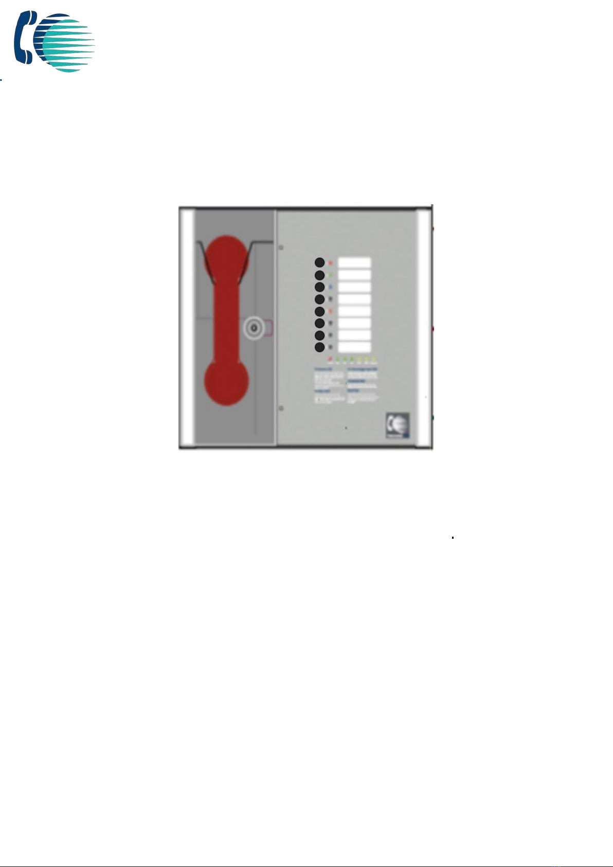
The Haescomm EVCS, or HC-228S, comprises of a Master Station and one or more outstations.
Additionally, the “Assist Call” emergency assistance alarm system can either be connected to the same
line as a Type B outstation or connected to a dedicated line. Neither the outstations nor the “Assist
Call” emergency alarm system require a separate power supply unit as each line is powered from the
Master Station. This has the additional benefit of each line being fully monitored and battery backed up.
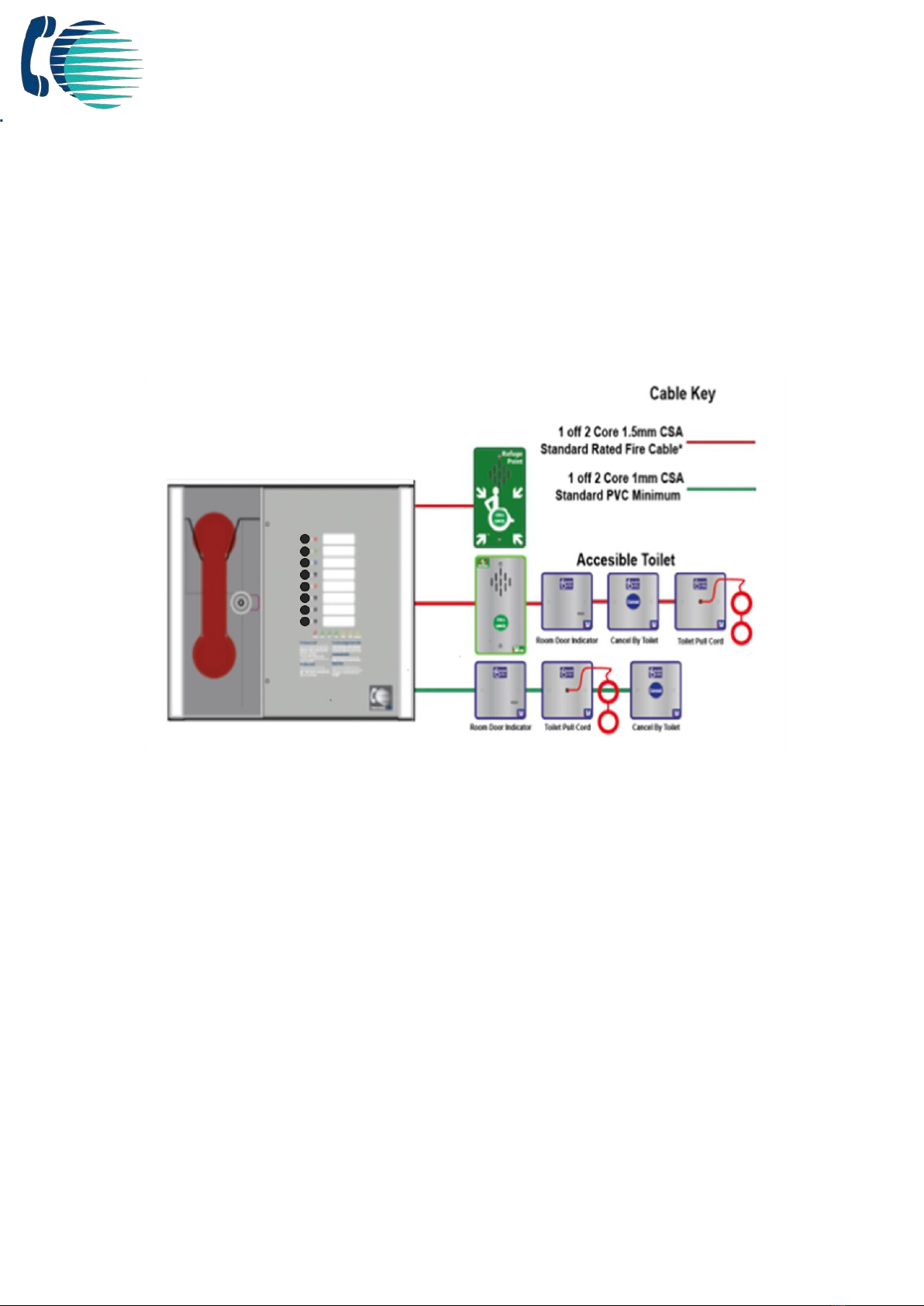
The HC-228S Master Station has been designed for radial star topology. In most cases this will reduce
the cable requirements for all ring-based systems. The topology consists of spurs formed of 1 off two
core 1.5mm CSA cables (soft skin enhanced up to 500m per leg, MICC 200m per leg) to each
outstation.

Page 4 of 21
3. Important Safety Information
This Equipment must only be installed and maintained by a suitably skilled and competent person.
This Equipment is defined as Class 1 in EN IEC62368-1:2020+A11:2020 (Low Voltage Directive) and
must be EARTHED.
Caution
Indoor Use Only
Warning
Shock Hazard-
Isolate Before Opening
Warning
TO REDUCE THE RISK OF FIRE OR ELECTRIC
SHOCK, DO NOT EXPOSE THIS UNIT TO RAIN
OR MOISTURE
Warning
THIS UNIT MUST BE EARTHED
Warning
NO USER SERVICEABLE PARTS
Each HC-228S Master Station requires local isolation with verification as per the Electricity at Work
Regulations 1989, returning to a B6A breaker clearly marked “EMERGENCY VOICE
COMMUNICATION SYSTEM. DO NOT TURN OFF”.
Anti-static handling guidelines
Make sure that electrostatic handling precautions are taken immediately before handling PCBs and other
static sensitive components.
Before handling any static-sensitive items, operators should get rid of any electrostatic charge by
touching a sound safety earth. Always handle PCBs by their sides and avoid touching any components.

Page 5 of 21
4. Unpacking the Unit
Remove the HC-228S Master Station from its packing, and check the contents against the following list:
●HC-228S Master Station.
●Quick start guide.
●Accessory pack with the following contents: -
o1 number 2.5mm AF Hex Key.
o1 number door handle/key.
oEnd of Line (EoL) Resistors, 2 per line card
Figure 1
Use the 2.5mm AF Hex Key supplied to open the right-hand front cover.
Verify the following items are present:
●Correct number of Line Card, depending on configuration. c/w 2-way line connectors.
●1 number 3-way mains connector.
●1 number 2-way Fault connector.
●1 number 2-way In Use connector.
●1 number 2-way Enable connector.
●1 number Battery lead.
If there are any items missing, please contact your supplier or Haes Technologies quoting the unit serial
number and the name on the packing list enclosed, so the situation can be rectified.

Page 6 of 21
5. Installation
Figure 2
Prior to mounting the HC-228S Master Station, it should be decided if the field wiring is to be run on the
surface or concealed. There are 14 knockouts on the top and 2 slotted entries with a dedicated mains
supply entry at the rear. If a knockout is removed by mistake, fill the hole with a good quality cable
gland.
Figure 3
Unused knockouts must be left unopened to comply with the Low Voltage Directive. Accidentally
knocked out holes should be blanked off.
EVC line
Connections
Mains
Supply
Relay
Contacts

Page 7 of 21
The HC-228S Master Station weighs 6kg with batteries, so care should be taken to securely mount the
Station on stud walling.
5.1 Connecting the HC-228S Master Station
To comply with EMC (Electro Magnetic Compatibility) regulations and to reduce the risk of electrical
interference in the system wiring, the use of fire-resistant screened cables is recommended throughout
the installation.
All wiring should come into the enclosure via the knockouts provided and be fixed tidily to the relevant
terminals.
Note that correct cable glanding is essential. Due regard should be paid to any system specifications
which demand a certain cable type, providing it meets the appropriate national wiring regulations.
5.2 Planning the Wiring
All system wiring should be installed to meet the appropriate parts of BS5839 Part9:2021 and BS 7671
(Wiring Regulations). Other national standards of installation should be adhered to where applicable.
Do not test wiring using an insulation tester (Megger) with any
equipment connected, as the 500 Volt test voltage will destroy
these devices.
You must observe local wiring regulations. Do not run SELV and LV cables in the same enclosure
without adequate insulation between them.
5.3 Cable and Wiring Guidance
5.3.1 Fire Telephone system
Any system for use as a fire telephone system should use Type A outstations and must use enhanced
grade cabling throughout for all wiring, including the mains supply to the HC-228S Master Station.
5.3.2 Disabled Refuge EVC System
For buildings less than 30m in height, or any building with sprinklers fitted, standard grade fire resistant
cable may be used to wire Type B outstation and the mains supply to the Master Controller if the
planned evacuation will be completed in 30 minutes.
If the building is over 30m in height without sprinklers, or where the evacuation will take place over
multiple stages exceeding 30 minutes, then enhanced grade cables must be used.
5.3.3 Combined Systems
Cabling to Type A or Type C outstations must be in enhanced grade fire resistant cabling.
Individual spurs to Type B outstations can be wired in standard grade fire resistant cabling in
accordance with the wiring guidelines already set out for disabled refuge systems.
5.3.4 “Assist Call” Emergency Assistance Alarm Systems
All installations must conform to Building Regulations Approved Document M. The “Assist Call” is wired
using 2 core cable, and the “Assist Call” plates can be wired in any order.
5.3.5 Cabling methods
There are 3 cabling methods available:
●Connection to a Type A or Type C outstation: use 2 core enhanced grade fire resistant cable
when extending a firefighting telephone system.
●Connection to a Type B outstation: use 2 core standard grade fire resistant cable when
extending a disabled refuge system.
●Connection to an “Assist Call” system on a dedicated line requires 2 core 1mm CSA or above
PVC sheathed.

Page 8 of 21
5.3.6 HC-228S Master Station Wiring
The wiring for a HC-228S Master Station is shown in the schematic below.
Figure 4
5.4 Mains Connection
Figure 5
Each HC-228S Master Station requires local isolation with verification as per the Electricity at Work
Regulations 1989, returning to a B6A breaker clearly marked “EMERGENCY VOICE
COMMUNICATION SYSTEM. DO NOT TURN OFF”.
5.5 Battery Information
In the event of mains failure BS 5839-9:2021requires battery backup for 24 hours standby and 3 hours
operation thereafter.
An HC-228S Master Station requires one number 12V 7AH valve regulated sealed lead acid battery.
The battery is not supplied with the HC-228S Master Station. Haescomm recommend a Yuasa NP7-12

Page 9 of 21
Safety Information:
Sealed Lead Acid batteries contain sulphuric acid which can cause burns if exposed to
the skin. The low internal resistance of these batteries mean large currents will flow
if they are accidentally short-circuited causing burns and a risk of fire.
Exercise caution when handling batteries.
Power Up Procedure:
Always apply mains power before connecting batteries. When connecting batteries,
always connect the Positive (Red +) terminal first.
Power Down Procedure
Disconnect the batteries before removing the mains power. When disconnecting
batteries, always remove the Negative (Black –) terminal first.
5.6 Outstation Connections
The HC-228S Master Station is equipped with at least one number Dual line card. One outstation per
line output can be connected. If no outstation is connected to the line output, then an end of line 10kΩ
resistor should be fitted. The dipswitch located on the rear of the door mounted Display PCB is used for
configuration see 6.1
The following devices are available on the system:
●Type A (fixed phone)
●Type B (hands-free refuge point)
●Type C “Combi” (combined Type A and Type B)
●Jack point
●“Assist Call” emergency assistance alarm system
For Type A, and Type C outstations the end-of-line 10kΩ resistor is not required as it is integral to the
product. For Type B outstations the end-of-line 10kΩ resistor should be removed from the accessory
pack and connected to the end-of-line terminal in the outstation.
For Jack points and the “Assist Call” system, the end-of-line 10kΩ resistor should also be removed from
the accessory pack and connected to the last plate on the system.

Page 10 of 21
5.6.1 Type A outstation
Figure 6
Note: The Earth screen should be sleeved and connected to the terminal block in the controller,
and the earth stud in the Type A outstation.
5.6.2 Type B outstation
Figure 7
Note: The Earth screen should be sleeved and connected to the terminal block in the controller,
and the earth connection in the metal back box (if a plastic back-box is used cut the earth back
and insulate at the outstation.)

Page 11 of 21
5.6.3 ACA Accessible Toilet Kit
Figure 8
The ACA kit comprises an Over door Indicator, a pull cord and a cancel plate and they can be wired in
any order, the above is typically as installed, and runs Overdoor Plate, ceiling Pull and then the Cancel
plate, the EOL resistor goes in the free terminals of the last plate.
5.7 Auxiliary Connections
The HC-228S Master Station has three auxiliary connections:
Fault is a normally closed volt free relay (30V DC 1A) which OPENS
on any fault, including loss of power.
In Use is a normally open volt free relay (30V DC 1A) connection
which closes when any outstation is operated, see Remote Signal
Display section 7.5 switch settings for further information.
Enable is a normally CLOSED input and is required to operate the
system, this is often connected to the fire alarm system. If Jumper
J9 is in place, then no connection is required at the terminals. This
function only disables Type B outstations, with Type A outstations
and “Assist Call” emergency assistance alarm systems continuing to operate. Calls from Type B
outstations automatically “time out” after approximately 30 minutes. It is advised that this feature is
not used as the system should always be available, not just during an evacuation. If the feature is used,
then the mode LED illuminates yellow after 30 seconds to show that the system is disabled.
Note. If the system is disabled, the master station can still make outgoing calls.
5.8 Powering up procedure
To power up the HC-228S Master Station, carefully check all internal wiring before applying mains
power to the HC-228S Master Station. Once the HC-228S Master Station is powered, the battery can be
attached using the battery leads supplied. When attaching the battery, always attach the Positive
(Red+) terminal first.
5.9 Powering down procedure
To power down the HC-228S Master Station, first disconnect the battery. Always disconnect the
Negative (Black -) terminal first. Once the battery leads have been disconnected, then remove mains
power.
6. Set up procedure
The HC-228S Master Station has various site configurations which are configured using the dipswitch
located on the rear of the Display PCB.
Figure 9

Page 12 of 21
Figure 10
6.1 HC-228S Master Station Display PCB Dipswitch Settings
1
2
3
4
5
6
7
8
Line
1&2
Line
3&4
Line
5&6
Line
7&8
NA
NA
NA
Reserved
Remarks
✔
NA
NA
NA
Line card 1 fitted
✔
✔
NA
NA
NA
Line card 1, 2 fitted
✔
✔
✔
NA
NA
NA
Line card 1, 2, 3 fitted
✔
✔
✔
✔
NA
NA
NA
Line card 1, 2, 3, 4 fitted
Figure 11
✔= Dipswitch in ON position
x = Dipswitch in OFF position
Exchange PCB Diagram-
Figure SEQ
Figure \*
ARABIC 12

Page 13 of 21
Figure 13
6.2 Adding a Line Card
The HC-228S Master Station is supplied with at least one number Line Card. There are 2 lines per
Line Card.
Before adding a Line Card, ensure that the HC-228S Master Station is not powered. If the HC-228S
Master Station is powered, then power down the HC-228S Master Station (see 5.9).
To fit the Line Card:
1. Place Line Card in the next available space on the Exchange PCB and secure using
the supplied screw.
2. Remove the line terminal and connect the field wiring.
3. Push the terminal into the correct position on the Line Card.
4. Set the dipswitch on the Display PCB (see 6.1) to enable Line Card monitoring.
Once the Line Card is securely fitted, power up the HC-228S Master Station (see 5.8).
6.3 Removing a Line card
Before removing a Line Card, ensure that the HC-228S Master Station is not powered. If the HC-228S
Master Station is powered, then power down the HC-228S Master Station (see 5.9).
To remove the Line Card:
1. Remove all line terminals from the Line Card that is to be removed.
2. Remove the securing screw.
3. Remove the Line Card from Exchange PCB.
4. Set the dipswitch on the Display PCB (see 6.1) to disable Line Card monitoring.
Once the Line Card has been removed, the HC-228S Master Station may be powered (see 5.8).
7. System Menus
7.1 Login Procedure
For access level 2 (User) the code is 1664, for access level 3 (Engineer) the code is 1812. Enter the
relevant code using the numbered buttons 1-8, as each button is pressed the user LED will flash
cyan/magenta faster until the required code is entered, at which point LEDs 1-3 will illuminate cyan for
User mode and LEDs 1-5 will illuminate magenta for Engineer mode.
7.2 Fault Accept
Before accepting faults, the fault must be noted in the logbook, along with the time the fault was
reported.
To accept the fault, enter either the access level 2 (code: 1664) or access level 3 (code: 1812) menu,
then press zone button 1. The buzzer will silence, and the general fault LED will now go steady.
Press zone button 8 to exit this menu and to return to the menu options.
The buzzer will resound on each new fault and after 8 hours.

Page 14 of 21
7.3 Panel Indicator Test
To test the panel indicators, enter either the access level 2 (code: 1664) or access level 3 (code: 1812)
menu, then press zone button 2.
All LEDs will illuminate in a predefined sequence, and the buzzer will sound.
Press zone button 8 to stop the panel indicator test and to return to the menu options.
7.4 Extended Fault Menu
Enter the access level 2 code (1664) or access level 3 (code: 1812) then press zone button 3.
Zone
Indicator Status
Description
1-4
Blank
Line card configured as not fitted
Yellow Solid
Line card configured as fitted but not present
Green Solid
Line card configured as fitted and present
5
Not Used
Not Used
Not Used
6
Not Used
Not Used
Not Used
7
Green Solid
Display Processor Healthy
Yellow Solid
Display Processor Fault
8
Green Solid
Exchange Processor Healthy
Yellow Solid
Exchange Processor Fault
7.5 Remote Signal Delay Timer
The in-use relay, function can be altered to provide a remote signal via an auto dialler, BMS or similar.
The delay is adjustable between 30 seconds and 3 minutes such that if a call from an outstation is not
answered within the chosen time delay then the relay operates. This could be used to send a signal off
site during periods when the master station is not attended.
If the call is answered during the delay period, the relay will not operate, and the timer will cease.
The above function works identically with the Assist Call emergency assistance system.
Enter the access level 3 code (1812), then press button 4 to enter this mode. The magenta zone
indicators from 1 to 8 will be illuminated depending on selection, pressing button 2 will give a 30 second
delay, button 3 a one-minute delay and so on to button 7 which gives a three minute delay. When the
required delay is selected the adjacent indicator will illuminate to confirm the delay period. Press button
8 to exit this mode.
Button
Delay Timer Options
1
No Delay
2
30 Secs
3
1 Min
4
1 min 30 secs
5
2 min
6
2 min 30 secs
7
3 min
8
Exit
7.6 In Use Relay Options
The in-use relay has programmable functions which can work in tandem with the delay timer described
in 7.5. These functions can provide a relay output as described in the table below:
These relay functions can be useful for providing an output of specific system operation of EVC, Assist
Call or both. This relay can also be used to connect to the HC-RAP Remote Alarm panel or a remote
sounder or beacon which can be configured to cancel operation when the master handset is picked up
such that the sounder will not interfere with the conversation.
Enter the access level 3 code (1812), then press button 5 to enter this mode. The magenta zone
indicators from 1 to 8 will be illuminated depending on selection. When the required selection has been
made press button 8 to exit this mode.

Page 15 of 21
Button
Relay Option
1
Not Used
2
EVCS & Assist Call
3
EVCS only
4
Assist Call Only
5
Relay activates on any call, Relay de-energises on master handset pickup
6
Relay operates when call not answered /acknowledged (EVCS and Assist Call)
8
Exit
8. Operation
All conversations are under the command of the HC-228S Master Station.
8.1 Receiving a call
One of the eight zone LEDs and the mode LED will flash red to indicate an incoming call. The flash rate
will identify the outstation type, with a Type A outstation having a faster flash rate than a Type B
outstation.
Lift the Master handset receiver. The User LED will illuminate Red.
Press the corresponding zone button (indicated by the red flashing LED). This LED and the User LED
will change to flashing green to show that this line is now connected, and a conversation can take
place.
8.2 Making a call
To make a call, lift the Master handset receiver and the User LED will illuminate red.
Press the zone button for the required outstation. The corresponding zone LED will flash red. This flash
rate will be slower than the flash rate for either an incoming Type A or Type B call.
When the outstation answers the call, the zone LED flashes green, the mode LED illuminates red and
the user flashes green to indicate this line is now connected and a conversation can take place.
8.3 Ending a call
To end the call from the outstation, either replace the Type A receiver back on its hook or press the
call/cancel button for a Type B outstation.
To end a conversation from the HC-228S Master Station, replace the Master handset receiver back on
its hook.
Note: This will not end the call, only the conversation. The outstation will revert back to requesting a
call, and the zone LED will flash red to indicate this. The call MUST be ended at the outstation.
8.4 Putting a call on hold
To put a call on hold, press the zone button to select outstation that is already connected. The zone
LED will change from flashing green to flashing green/red. The user LED also flashes green/red and the
mode LED.
To reconnect the call, press the zone button for the required outstation again. The zone LED will
change from flashing green/red to flashing green to indicate the call is now connected again.
8.5 Conference Call
Depending upon the number of Line Cards fitted in the HC-228S Master Station, up to five lines can be
connected to the conference call at any one time. To receive a call, see 8.1. To make a call to an
individual outstation, see 8.2. The HC-228S Master Station controls which lines are involved in the
conference, and only one conference group is allowed.
8.6 Acknowledging “Assist Call” alarms
When an “Assist Call” goes into alarm, the appropriate zone LED will flash blue, and a two-tone buzzer
sounds to indicate that an “Assist Call” alarm has been operated.
To acknowledge the alarm, press the corresponding zone button, and the blue LED will illuminate
continuously with an intermittent buzzer tone every 15 seconds. If after 2 minutes the “Assist Call”
alarm has not been cancelled, the buzzer will resound and the LED will flash blue.
Within the WC cubicle the pull cord indicator will change from continuous indication to no indication.
The cancel plate will alter from flashing to continuous and the buzzer will change from continuous to
intermittent. Outside the cubicle the Over door plate indication will alter from flashing to continuous and
the buzzer will change from continuous to intermittent. This change in indication and buzzers during the
acknowledge phase indicates to the WC user that help is on the way.

Page 16 of 21
8.7 Accepting Faults
Before accepting faults, the fault must be noted in the log book, along with the time the fault was
reported.
To accept the fault, enter either the access level 2 (code: 1664) or access level 3 (code: 1812) menu,
then press zone button 1. The buzzer will silence and the general fault LED will now go steady.
Press zone button 8 to exit this menu and to return to the menu options.
The buzzer will resound on each new fault.
8.8 Panel Indicator Test
To test the panel indicators, enter either the access level 2 (code: 1664) or access level 3 (code: 1812)
menu, then press zone button 2.
All LEDs will illuminate in a predefined sequence, and the buzzer will sound.
Press zone button 8 to stop the panel indicator test and to return to the menu options.
9. Indications and Controls
Figure 14
9.1 Mode Indicator Summary
Mode
Description
Green solid
Normal state
Red solid
Outstation off hook
Blue solid
Assist call active
Yellow Solid
Refuge (type B) points disabled
Flashing Red/Blue
Incoming call/ Assist Call alarm at same time
Figure 15

Page 17 of 21
9.2 Power supply and CPU indicator Summary
AC
DC
PSU
General
CPU
Description
✔
Mains OK
x
Flash
Flash
Mains failure
✔
✔
Battery OK
✔
x
Flash
Flash
Battery open circuit
✔
x
✔
Flash
Battery short circuit
✔
Flash
✔
Flash
Battery high impedance
✔
✔
Flash
✔
PSU processor fail
✔
Flash
✔
Display or Exchange Processor Fault or Display-Exchange comms flt
✔
Flash
Display or Exchange Processor Fault or Display-Exchange comms flt
on remote panel (if applicable)
✔
Flash
Flash
Remote Battery fault
Flash
Flash
Remote Mains fault
Figure 15
✔= LED illuminated
x = LED off
Flash= LED Flashing
Note: When faults are accepted the general LED illuminates solid.
9.3 User Indicator Summary
Red
Master handset off hook
Flashing Yellow
Master handset open circuit
Cyan
User logged in
Magenta
Engineer logged in
Flashing green
Call connected
Flashing Red/Green
Call on hold
Solid Yellow
Master handset short circuit
Figure 16
9.4 Zone indicator summary
Zone Indicator Status
User Indicator Status
Buzzer Status
Description
Slow flash red
Off
Outgoing call
Fast flash red
Ringing
Incoming call from type A outstation
Normal flash red
Ringing
Incoming call from type B outstation
Normal flash green
Normal flash green
Off
Call connected to master handset
Normal flash green/red
Off
Call on hold
Solid yellow
On
Line Short circuited
Slow flash yellow
On
Line card missing
Normal flash yellow
On
Line Open circuit or EOL missing
Fast flash yellow
On
Line Earth fault
Solid cyan
Solid cyan
Off
Access level 2
Solid magenta
Solid magenta
Off
Access level 3
Normal flash blue
2 Tone Alarm
Incoming Assist Call alarm
Solid blue
Intermittent
double Beep
Assist call acknowledged
Figure 17

Page 18 of 21
10. Commissioning procedure
The commissioning should be carried out by a competent person who has a basic knowledge and
understanding of the design and installation sections of BS 5839-9:2021and has access to the
specification of the project.
10.1 Cable Checks
The 500v insulation tests should have been carried out by the installer and the results made available to
the commissioning engineer.
All cables should be correctly labelled.
Test field wiring and check for end-of-line 10KΩ resistor. Check cables are clear from any short or open
circuits.
Connect cables into Line Cards.
10.2 Set up, power up
Configure relevant dipswitches for the number of Line Cards fitted, these should have been factory set.
Power up the HC-228S Master Station using mains only, fed via a double fitted in an unswitched fused
spur. The AC power indicator will be illuminated, and the DC power indicator is extinguished. The PSU
fault and General fault indicators will be illuminated. There should be no line fault indicators
illuminated.
If there are no line faults present, the battery may be connected. The DC power indicator will be
illuminated, and the PSU fault and General fault indicators are extinguished when battery is connected.
If there are any line fault indicators illuminated, then the field wiring should be checked prior to the
battery being connected.
10.3 Intelligibility Tests
Lift the master handset receiver and listen for a cadence tone.
An intelligibility test will need to be performed when the system is complete and the building has normal
background noise levels. The intelligibility test requires two personnel.
One person should be present at the master station, the other person should visit each outstation in
turn and put the outstation into call. The master station operator should check the location of the
outstation is correct and have a conversation, the master station operator should then call the
outstation back to check the reverse operation.
10.4 Assist Call Checks
Where Assist Call is fitted, all pull cords in each circuit should be tested, acknowledged at the panel,
cancelled at the call location. Ensure all controls and indicators operate correctly.
11. Maintenance
It is a requirement of BS 5839-9:2021 that a maintenance agreement be in place for the EVCS. The
maintenance schedule should be as follows:
Frequency
Test
Weekly
Test a different outstation on the system each week and make a call to the master
station. Repeat each week until all outstations and master stations are tested. Record
these results in the site log. *if more than one master station is present alternate
weekly.
Non EVC mode devices should also be tested for correct operation, at a frequency of
at least 1 per week so that all devices are tested over a 12 month period.
Biannually
Engineer call to check system operation perform 100% outstation and master station
operation, field strength of attached AFILS equipment and check battery health.
Record results and any variations into the site Logbook.
5 Yearly
In addition to Yearly tests replace all batteries and record in Log Book.
Refer to BS 5839-9:2021 for full details of maintenance and testing requirements.

Page 19 of 21
12. Outstation zone template
There is space to the right of each outstation zone indicator to name the location of the outstation. At
the rear of the display door there is a slot located in the centre above the display PCB; the outstation
zone template can be inserted here.
The template is in “Word” format and can be downloaded at www.haes-tech.com . Go to downloads
section. This can be completed, printed out and cut to size as shown below.
✂
TAB
Refuge 1 Name
Toilet 1 Name
Refuge 2 Name
Toilet 2 Name
Refuge 3 Name
Toilet 3 Name
Refuge 4 Name
Toilet 4 Name
Refuge 5 Name
Toilet 5 Name
Spare 1
Spare 2
Spare 3

Page 20 of 21
Notes
Table of contents