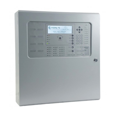
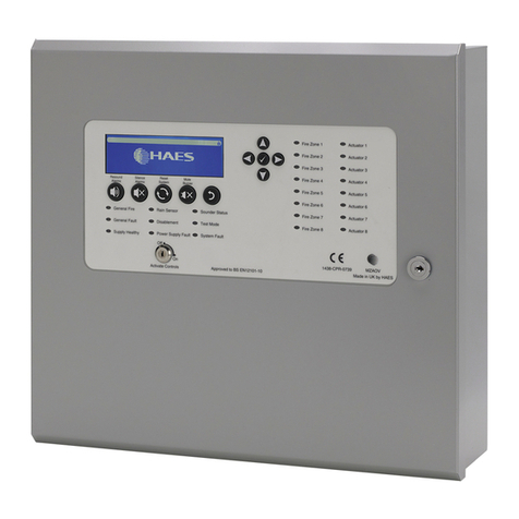
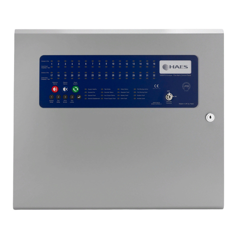
Haes MZAOV-1001 Guide

MULTIZONE
AUTOMATICALLY
OPENING VENT
(MZAOV) CONTROL
PANEL INSTALLATION,
COMMISSIONING &
OPERATING MANUAL
This manual covers the installation, programming and
commissioning of theMultizone Automatically Opening Vent Control
Panel

Multizone AOV User Manual INTRODUCTION
1
Approved Document Ref: UI-MAOV-01 Issue 1.0
INTRODUCTION
1438
Haes Technologies Ltd, Unit 3, Horton Industrial Park, West Drayton, Uxbridge, UB7
8JD
Model Number CPR Number
MZAOV-1001/-1002/-1003 1438-CPR-0739
European Standard EN54-4: 1998
Power supply equipment for fire detection and fire alarm systems for buildings.
Haes Technologies Ltd declare that the products identified above conform to the essential
requirements specified in the Construction Products Regulation CPR305/2011/EU.
In addition, the product complies with the following:
2014/35/EC, Low Voltage Directive
2014/30/EC, Electromagnetic Compatibility Directive
BS EN 61000-6-3:2007 + A1:2011, Electromagnetic Compatibility (EMC) General Standards.
Emission standard for residential, commercial & light industrial environments.
BS EN 12101-2:2017 Smoke and heat control systems. Natural smoke and heat exhaust
ventilators
BS EN 12101-10:2005 Smoke and heat control systems –Part 10: Power supplies
This product has been designed to comply with the requirement of the low voltage safety and
the EMC directives. Failure to follow the instructions may compromise its adherence to this
standard.

Multizone AOV User Manual INTRODUCTION
2
Approved Document Ref: UI-MAOV-01 Issue 1.0
List of optional functions with requirements:
EN54-4: 1997 +A2
Power supply equipment for fire detection and fire alarm systems for buildings.
Non-standard
Provided Options:
Charge during alarm
Earth fault monitoring
UPS Mode
Changeable password for Level 2
Adjustable Date & Time

Multizone AOV User Manual SAFETY
3
Approved Document Ref: UI-MAOV-01 Issue 1.0
SAFETY
IMPORTANT NOTICE
PLEASE READ THIS MANUAL CAREFULLY BEFORE HANDLING THE EQUIPMENT AND
OBSERVE ALL ADVICE GIVEN WITHIN IT.
THIS PARTICULARLY APPLIES TO THE PRECAUTIONS NECESSARY TO AVOID
ELECTRO-STATIC DISCHARGE
Important Safety Notes
The panel is safe to operate provided it has been installed in compliance with the
manufacturer’s instructions and used in accordance with this manual.
Hazardous voltages are present inside the panel—DO NOT open it unless you are qualified
and authorised to do so. There is no need to open the panel’s enclosure except to carry out
commissioning, maintenance and remedial work. This work must only be carried out by
competent service personnel who are fully conversant with the contents of the panel’s
installation manual and have the necessary skills for maintaining this equipment.
This fire alarm system requires periodic checks as specified in BS 5839 Part 1 It is the
responsibility of the system user to ensure it is regularly serviced and maintained in good
working order.
The product must be installed, commissioned and maintained for operation in accordance with
the instructions and the applicable wiring codes of practice and national standard regulations
for fire systems appropriate to the country and location of the installation.
This equipment is designed to be operated from 230VAC 50/60 Hz mains supplies and is of
Class I construction. As such it must be connected to a protective earthing conductor in the
fixed wiring of the installation. Failure to ensure that all conductive accessible parts of this
equipment are adequately bonded to the protective earth will render the equipment unsafe.
Disclaimer
No responsibility can be accepted by the manufacturer or distributors of this fire alarm panel
for any misinterpretation of an instruction or guidance note or for the compliance of the system
as a whole. The manufacturer’s policy is one of continuous improvement and we reserve the
right to make changes to product specifications at our discretion and without prior notice. E &
O E.
Warnings
Before installation, refer to the Ratings shown on the label inside the product
and to the ‘Specifications Chart’ in this document. If you are unclear on any
point, please DO NOT proceed. Contact the manufacturer or supplier for
clarification and guidance.
Only Trained service personnel should undertake the Installation,
Programming and Maintenance of this equipment.
!

Multizone AOV User Manual SAFETY
4
Approved Document Ref: UI-MAOV-01 Issue 1.0
Cautions
Equipment Guarantee
This product has been manufactured in conformance with the requirements of
all applicable EU Council Directives and is not guaranteed unless the complete
system is installed and commissioned in accordance with the laid down national
standards by an approved and competent person or organisation.
This product has been designed to comply with the requirements of the Low Voltage Safety
and the EMC Directives. Failure to follow the installation instructions may compromise its
adherence to these standards.
Waste Electrical and Electronic Equipment Directive

Multizone AOV User Manual TABLE OF CONTENTS
5
Approved Document Ref: UI-MAOV-01 Issue 1.0
TABLE OF CONTENTS
INTRODUCTION ..................................................................................................................1
SAFETY................................................................................................................................3
IMPORTANT NOTICE.......................................................................................................3
Important Safety Notes......................................................................................................3
Disclaimer..........................................................................................................................3
Warnings........................................................................................................................3
Cautions.........................................................................................................................4
TABLE OF CONTENTS........................................................................................................5
PRODUCT OVERVIEW........................................................................................................9
General Description of the Equipment ...............................................................................9
Multi-AOV Cabinet........................................................................................................11
Circuit Boards...............................................................................................................12
PSU AOV Card –PCB-3037-212..............................................................................12
MULTI AOV Card (2-Way) –PCB-3038-212 .............................................................13
PIR/BMS (Plug-in) Card (2-Way) –PIR-0-10-3041-212 (Optional) ............................14
Circuit Description/Function..........................................................................................15
PSU AOV Card –PCB-3037-212 (TPCA027)............................................................15
MULTI AOV Card (2-Way) –PCB-3038-212 (TPCA028)...........................................16
PIR/BMS Plug-in Card (2-Way) –PIR-0-10-3041-212 (TPCA029) (Optional)............18
Technical Specification....................................................................................................20
General Specification ................................................................................................20
Power Supply Specification –PSM3 - 24 (MZAOV-1001 (3 Amp))............................21
Power Supply Specification –PSM5 - 27 (MZAOV-1002 (5 Amp))............................22
Power Supply Specification –PSM10-27 (MZAOV-1003 (10 Amp))..........................23
Electrical Specification - Inputs & Outputs.................................................................24
Electrical Specification - Inputs & Outputs.................................................................25
DESIGN CONSIDERATIONS.............................................................................................26
System Design and Planning...........................................................................................26
What is a detection zone? ............................................................................................26
Detectors......................................................................................................................26
Call Points....................................................................................................................26
Sounders......................................................................................................................27
Beacons .......................................................................................................................27
General ........................................................................................................................27
Cable Types and Limitations.........................................................................................27
Cabling......................................................................................................................27

Multizone AOV User Manual TABLE OF CONTENTS
6
Approved Document Ref: UI-MAOV-01 Issue 1.0
Cable Lengths...........................................................................................................28
Mains Provision............................................................................................................28
Detector Circuit Conventional System Schematic......................................................29
Detector Circuit Twin Wire System Schematic...........................................................30
Twin Wire Mode............................................................................................................31
INSTALLATION ..................................................................................................................32
Safety..............................................................................................................................32
ESD Precaution............................................................................................................32
Installing the System........................................................................................................33
General ........................................................................................................................33
Environment.................................................................................................................33
Mounting the Cabinet....................................................................................................33
Mains Connections.......................................................................................................34
Connecting the Batteries ..............................................................................................34
Battery Charging Voltage Checks.................................................................................35
Battery Charging Voltage Calibration............................................................................36
Sounders/Output Circuits..............................................................................................37
Relay Outputs...............................................................................................................37
Inputs - Class Change and Pulse .................................................................................38
Class Change............................................................................................................38
Pulse.........................................................................................................................38
P-BUS.......................................................................................................................38
Remote Status Unit Wiring ...........................................................................................38
OPERATING INSTRUCTIONS...........................................................................................39
Panel Control and Indicators............................................................................................39
Control Panel................................................................................................................39
Keypads....................................................................................................................40
Status LED Indicators................................................................................................41
User Controls...................................................................................................................42
General User Controls..................................................................................................42
Available Functions...................................................................................................42
Authorized User Controls..............................................................................................42
Available Functions...................................................................................................43
Authorised User Menu Options..................................................................................43
Engineer Controls.........................................................................................................44
Available Functions...................................................................................................44
Engineer Menu Options.............................................................................................44
Panel Alarm Conditions ...................................................................................................45

Multizone AOV User Manual TABLE OF CONTENTS
7
Approved Document Ref: UI-MAOV-01 Issue 1.0
Fire Alarm Condition.....................................................................................................45
Fault Condition .............................................................................................................45
Functionality during a system fault.............................................................................45
CONFIGURING THE SYSTEM...........................................................................................47
Accessing the Menu Structure.........................................................................................47
User Menu.......................................................................................................................49
User Menu: DISABLE...................................................................................................50
Disable Menu: REMOVE ALL Disablement...............................................................50
DISABLE Menu: GENERAL ......................................................................................51
DISABLE Menu: CIRCUIT.........................................................................................52
User Menu: TEST.........................................................................................................52
TEST MODE: ON/OFF..............................................................................................53
TEST MODE: SETTINGS..........................................................................................53
User Menu: Time & Date..............................................................................................54
User Time & Date Menu: Time & Date ......................................................................54
User Time & Date Menu: Set DST.............................................................................55
User Menu: Lamp Test.................................................................................................56
User Menu: Contrast ....................................................................................................57
User Menu: BUZZER....................................................................................................57
User Menu....................................................................................................................58
CONFIG Menu.................................................................................................................61
CONFIG Menu: PANEL................................................................................................62
CONFIG PANEL Menu: LEARN................................................................................62
CONFIG PANEL Menu: OPTIONS............................................................................63
CONFIG PANEL Menu: DEFAULT............................................................................64
CONFIG PANEL Menu: Password ............................................................................65
CONFIG Menu: CIRCUIT .............................................................................................65
CONFIG CIRCUIT Menu: CONFIG CIRCUIT............................................................65
CONFIG Menu: DEVICES............................................................................................66
CONFIG DEVICES Menu: VENT...............................................................................66
CONFIG DEVICES Menu: ZONES............................................................................68
CONFIG DEVICES Menu: SOUNDERS....................................................................69
CONFIG DEVICES Menu: Relay...............................................................................70
CONFIG Menu: PSU ....................................................................................................70
CONFIG Menu: P-BUS.................................................................................................71
CONFIG Menu..............................................................................................................72
Report Menu....................................................................................................................79
Report Menu: EVENTS.................................................................................................80

Multizone AOV User Manual TABLE OF CONTENTS
8
Approved Document Ref: UI-MAOV-01 Issue 1.0
Report EVENTS Menu: ALARM................................................................................80
Report EVENTS Menu: FAULT.................................................................................81
Report EVENTS Menu: DISABLE..............................................................................82
Report EVENTS Menu: TEST ...................................................................................83
Report EVENTS Menu: OTHER................................................................................84
Report Menu: STATUS.................................................................................................85
Report STATUS Menu: AOV.....................................................................................85
Report STATUS Menu: PSU Card.............................................................................86
Report STATUS Menu: BATTERY ............................................................................86
Report Menu: HISTORY...............................................................................................87
Report Menu: COUNTER.............................................................................................88
Report Menu: Versions.................................................................................................88
Report Menu.................................................................................................................90
ENG Menu.......................................................................................................................92
ENG Menu: OUTPUTS.................................................................................................92
ENG Menu....................................................................................................................93
SERVICE & MAINTENANCE..............................................................................................94
The Need for Maintenance ..............................................................................................94
Duties of the Responsible Person....................................................................................94
Routine Maintenance and Testing....................................................................................94
Daily.............................................................................................................................94
Weekly .........................................................................................................................94
Periodic Inspection and Servicing.................................................................................95
EVERY FOUR YEARS.................................................................................................95
SCHEDULE OF TESTING..................................................................................................96

Multizone AOV User Manual PRODUCT OVERVIEW
9
Approved Document Ref: UI-MAOV-01 Issue 1.0
PRODUCT OVERVIEW
Quality, reliability, ease of use and feature rich are attributes that are consistent across the
entire range of Haes fire alarm control panels.
The panels are available with three output options, 3 Amp, 5 Amp and 10 Amp for controlling
medium to large loads. The 3A and 5A panels can have between 1 and 4 Conventional and/or
Twin Wire (sav-wire) detector zones and will control between 1 and 4 vents. The 10A panel
can have between 1 and 8 Conventional and/or Twin Wire (sav-wire) detector zones,
controlling between 1 and 8 vents.
For the fire alarm engineer, the panel has been designed to be easy to install and to minimise
labour costs, by providing ample room for tasks such as wiring and changing batteries.
Activation is via key switch or access code, which means you should always be able to work
on the panel and the one man walk tests will help reduce the cost of maintaining the fire alarm
system.
The MAOV panel is designed to be intuitive and flexible for the fire alarm engineer to
programme and incorporates alarge 240 x 64-pixel graphical display, with an easy-to-navigate
menu system, which uses simple discernible icons in each section.
Simplicity is one of the most important aspects when considering the end user of a fire alarm
panel. The easy to read control panel, with its graphical LCD display and five marked control
buttons, and the 3-step silence functionality gives non-technical people the confidence to
correctly manage their fire alarm system.
All inputs and outputs are fully programmable and there are options to have delays to the
outputs (including vent opening). The programming features also include 3 different modes to
help reduce false alarms. Local fire authorities are demanding this type of functionality to
reduce unwanted callouts from alarm receiving centres.
The MAOV acts as an automatic multi-zone smoke vent opening control panel. The panels
are designed to control up to eight 24VDC motorised vents, which use a polarity reversal to
control vent direction. The MAOV panel can be configured to open the vents in a controlled
sequence, to aid smoke venting. The actuator output can also be configured for the control of
magnetic vents or other purposes.
The panel supports connections for up to 32 Remote Status Units (RSUs), remote control call
points and repeaters, via an RS-485 Peripheral BUS (PBUS) circuit. The PBUS circuit is not
intended for networking.
MAOV panels support a large range of conventional detectors including, Apollo, Hochiki &
Nittan.
MAOV panels are approved to European standards EN54-4, Fire Detection and Alarm
Systems –Control & Indicating Equipment.
This product has been designed and manufactured in the United Kingdom.
General Description of the Equipment
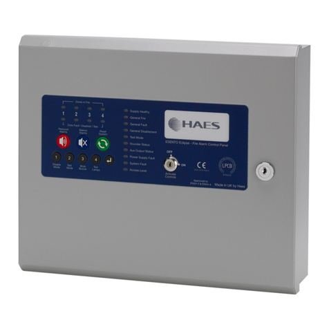
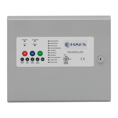
The panels have either 1 to 4 or 1 to 8 detector zones and are supplied in two different
enclosure sizes; with the 3A and 5A versions in a smaller cabinet, with space for two 12Ah
batteries and the 10A version in a larger cabinet with space for two 18Ah batteries. These
modules comply with the requirements of EN54-4: 1988 and provide temperature
compensated battery management charging.
Multizone AOV User Manual PRODUCT OVERVIEW
10
Approved Document Ref: UI-MAOV-01 Issue 1.0
Additional control input/output cards are available, allowing for the use of PIR sensors, to
prevent vents from closing when a trap hazard (i.e. arm or hand) exists, and rain sensors for
inclement weather.
The panels have a sheet steel enclosure, suitable for wall mounting, with a hinged and
lockable front access door. Cable entry is via 20mm knockouts located at the top and rear of
the cabinet.
Different key types are used for the door lock and the ‘Activate Controls’ key switch.
The panel is fully configurable and uses an easy to navigate menu system, which utilizes a
large 240 x 64-pixel graphical display and 5-button Up/Down/Left/Right/Enter (✓) curser
control keys for menu navigation. The panel internal sounders and external alarm sounders
are controlled by a 5-button keypad. Thecontrols are accessible by either an Activate Controls
key switch, or via a 4-digit code entry, if preferred.
The panels are designed to control up to eight 24VDC motorised vents, which use a polarity
reversal to control direction. Each output can be configured to also control magnetic vents.

Multizone AOV User Manual PRODUCT OVERVIEW
11
Approved Document Ref: UI-MAOV-01 Issue 1.0
Multi-AOV Cabinet

Multizone AOV User Manual PRODUCT OVERVIEW
12
Approved Document Ref: UI-MAOV-01 Issue 1.0
Circuit Boards
PSU AOV Card –PCB-3037-212

Multizone AOV User Manual PRODUCT OVERVIEW
13
Approved Document Ref: UI-MAOV-01 Issue 1.0
MULTI AOV Card (2-Way) –PCB-3038-212

Multizone AOV User Manual PRODUCT OVERVIEW
14
Approved Document Ref: UI-MAOV-01 Issue 1.0
PIR/BMS (Plug-in) Card (2-Way) –PIR-0-10-3041-212 (Optional)

Multizone AOV User Manual PRODUCT OVERVIEW
15
Approved Document Ref: UI-MAOV-01 Issue 1.0
Circuit Description/Function
PSU AOV Card –PCB-3037-212 (TPCA027)
POWER IN A/POWER IN B (+ -)
Two monitored 28VDC inputs from power supply module. Diode protected for reversal and
independent short circuit. Maximum input current, 10 Amps. Input voltage 22 to 32VDC.
Configurable for either one, or both, of the inputs to be used.
SWITCH (OP C CL)
Control input from external 3-way fireman control switch, for manual control of all vents
simultaneously:
OP Activates the vent output (fully open vent)
C Common 0v reference
CL Activates the vent output (fully close vent)
In default condition, operation of this switch will fully open/close all vents together, overriding
local switch settings/vent positions.
Note: If a local vent control switch is configured as a local fireman switch, controlling one or
more local vents, control of those vents by an external 3-way fireman’s switch is overridden.
Note: If neither input is grounded, vent follows panel automatic control (AUTO)
PBUS 1/PBUS 2 (B A)
Inputs for two RS-485 Peripheral BUS (PBUS) circuits, for remote control call points and
repeaters (max. 32). The PBUS circuits are not intended for networking.
FIRE (C NC NO)
Common alarm changeover relay contacts, max 3A at 30VDC (unfused). Activate when an
alarm condition (470Ω) exists on a ZONE circuit or a trigger condition (2K7) exists on an
external Input circuit.
28V + -
28V output, fused at 500mA, for use by external auxiliary equipment (RDUs, PSUs, etc.).

Multizone AOV User Manual PRODUCT OVERVIEW
16
Approved Document Ref: UI-MAOV-01 Issue 1.0
SNDR 1 (+ -)/SNDR 2 (+ -)
Two 24VDC programmable and monitored sounder outputs, configurable as FARE and FWRE
(Fire and Fault routing).
They can be programmed to turn OFF or ON in Continuously mode or in Pulsing mode (1s
ON and 1s OFF).
The sounders can be configured to be non-silencing or silencing.
FAULT (C NC NO)
Common fault signal changeover relay contacts, max 3A at 30VDC (unfused). Normally
energised (failsafe) contacts change-over when any fault is active on the panel or in the event
of total power loss.
TEMP (+ -)
Connections for battery temperature sensor.
BATTERY (+ -)
Output connections for 12Ah or 18Ah VRLA batteries charging (temperature compensated).
27.3VDC output at 20C, Max. charging current: 700mA or 1.2A.
MULTI AOV Card (2-Way) –PCB-3038-212 (TPCA028)
Between one and two (3A/5A box) or one to four (10A box) Multi-AOV cards may be fitted,
allowing for up to eight vent zones (two per card).
ZONE 1/ZONE 2 (+ -)
Conventional/Twin Wire fire alarm zone circuit. Typical max. load of up to 22 devices, at 18mA
each, may be used in each zone circuit, monitored via a 6K8Ω 5% 0.25W end-of-line resistor.
Monitoring current limit is 50mA, fused at 500mA.
Detectors in the circuit may use schottky diode bases, for detector removal monitoring;
ensuring that if a detector is removed, other devices on the circuit are still functional.
Some programming options are available for these circuits, including the selection of ‘Twin
Wire’ mode. Please refer to the Configuring the System section.
Twin Wire mode allows the use of 24V alarm sounders and beacons on the same circuit as
detectors and call points, but in reverse polarity.
Note: In this mode, the detectors require special ‘Sav-Wire’ bases.
An alarm on the detector circuit will activate the vent outputs, in the same way as activation
inputs from the Fireman switch, local vent control switches, or other activation inputs.
INPUT 1/INPUT 2 (+ -)
Spare activation input (programmable). Alarm activating input; 2K7 alarm, 6K8 Ohm, 5%
0.25W, EOL resistor. Monitoring current limit 14mA, unfused.

Multizone AOV User Manual PRODUCT OVERVIEW
17
Approved Document Ref: UI-MAOV-01 Issue 1.0
ACT 1/ACT 2 (+ -)
Dual polarity reversal vent drive actuator outputs - 28VDC, max 8A, protected by a current trip
circuit. Not normally powered. Operated by the inputs from either the main fireman switch, or
the local vent control switches; for a configurable time-period of 10 to300 seconds. Thedefault
setting is 60 seconds, during configuration of the panel, this should be set to the time-period
required to open/close the vent fully. Polarity is reversed for vent closure. Both outputs, when
fitted, always operate fully.
On commissioning, the vent should be set to the fully closed position prior to connection. The
actuator outputs may be changed to a continuous, maintained operation during configuration.
SWITCH 1/SWITCH 2 (OP C CL)
Local vent control switch inputs, for manual operation of vents by local vent control switch(es).
•OP - Open vents
•C - Common 0V reference for switching inputs
•CL - Close vents
The local vent control switch in a vent zone operates the local vent, together with one or more
vents in other zones, depending on configuration.
Local vent control switches can be used as a local Fireman’s switch, for selected vents,
depending on configuration.
Note: The local vent control switch, when configured as a local fireman’s switch, has priority
over both the alarm condition vent configuration and the external 3-way Fireman’s switch
setting.

Multizone AOV User Manual PRODUCT OVERVIEW
18
Approved Document Ref: UI-MAOV-01 Issue 1.0
OUTPUT 1/OUTPUT 2 (NO C)
Reports when local vent zone is in alarm condition.
PIR/BMS Plug-in Card (2-Way) –PIR-0-10-3041-212 (TPCA029) (Optional)
One PIR card can be fitted to each of the Multi-AOV cards mounted in the panel. This means
up to eight PIRs can be fitted in the system.
PIR 1/PIR 2 (+ -)
The PIR input is available to monitor a typical security type PIR with N/C alarm and tamper
contacts. The PIR requires a 12VDC supply, taken from the boards 12V output. The input
requires a 10KΩ impedance to trigger, with a 6K8Ω 5% 0.25W EOL resistor. Monitoring
current limit is 14mA, unfused.
When operated, the PIR alarm prevents the vent from closing, to guard against entrapment
injury. The PIR should be mounted in accordance with the manufacturer’s instructions, to
detect any presence in the vicinity of the entrapment risk.
BMS 1/BMS 2 (0V IN OUT)
Building Management System control interface, using 0/10 volt proportional control signals:
•0V –Common 0V output. This is 0 volts common reference for 0/10V input and output
•IN –Positional voltage input. Accepts 0/10 volt (DC) signal in 1 volt steps per 10% of
motor time. Vent position is determined by running time, which by default is 60
seconds, i.e. 10% = 6 seconds running time, 50% = 30 seconds etc. Max input is
10VDC, with 75kΩ impedance.
•OUT –Positional voltage output. This output represents the position of the vent in 10%
steps of motor run time. Provides feed-back of the 0/10V input status and vent
positional information. Max output is 10VDC 2mA. Max 20KΩ load and 680R
impedance.

Multizone AOV User Manual PRODUCT OVERVIEW
19
Approved Document Ref: UI-MAOV-01 Issue 1.0
RAIN (+ -)
Signal input from wind/rain sensors. Typically, a wind/rain sensor will have a closing contact
alarm signal and may require a 24V supply. The input requires a 2K7Ωimpedance to trigger,
with a 6K8Ω 5%0.25W EOL resistor. Monitoring current limit is 14mA, unfused. Up to 4
wind/rain sensors can be installed in the system; any one of which can close all manually
opened vents but will not override an alarm signal input.
12V (+ -)
12VDC supply output for PIR use. Max continuous rated load 100mA, fused at 100mA
resettable fuse.
This manual suits for next models
2
Table of contents
Other Haes Control Panel manuals

Haes
Haes AlarmSense PLUS User manual

Haes
Haes ELAN HS-5100 User manual

Haes
Haes AOV Series Guide

Haes
Haes FCPTEC-HS-4200 Guide

Haes
Haes ESG-2001 Guide

Haes
Haes Excel-32 Series User manual

Haes
Haes ESPRIT-G Guide

Haes
Haes ELAN HS-5200 Assembly instructions

Haes
Haes FUSION 0832-CPD-1431 User manual

Haes
Haes AlarmSense Guide
Popular Control Panel manuals by other brands

CPflight
CPflight MCP737PRO3 manual

CAME
CAME ZC3C installation manual

Hydor
Hydor Bespoke Installation and maintenance instructions

Technicolor - Thomson
Technicolor - Thomson LDK 4629/00 Technical manual

Bresser
Bresser 7007400 instruction manual

Votronic
Votronic VPC Jupiter 100 Installation and operating manual