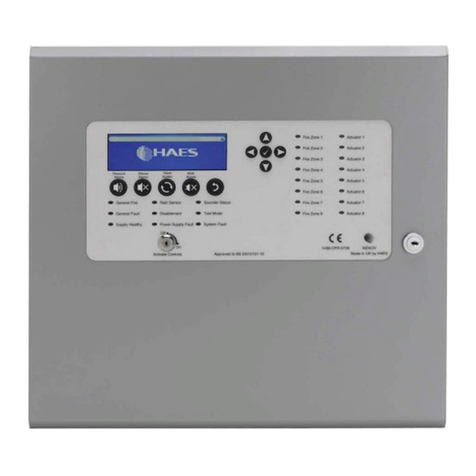
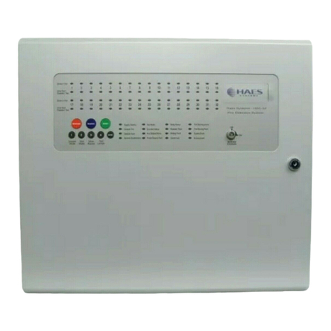
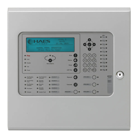
Haes AOV Series Guide

Installation, Commissioning &
Operating Manual
Automatically Opening Vent Control Panel
Approved Document UI-AOV-01 Issue 7.0

IMPORTANT NOTE
PLEASE READ THIS MANUAL BEFORE HANDLING THE EQUIPMENT AND
OBSERVE ALL ADVICE GIVEN IN IT
THIS PARTICULARLY APPLIES TO THE PRECAUTIONS NECESSARY TO AVOID
E.S.D
The panel is safe to operate provided it has been installed in compliance with the manufacturer’s instructions
and used in accordance with this manual.
Hazardous voltages are present inside the panel—DO NOT open it unless you are qualied and authorised
to do so. There is no need to open the panel’s enclosure except to carry out commissioning, maintenance
and remedial work. This work must only be carried out by competent service personnel who are fully
conversant with the contents of the panel’s installation manual and have the necessary skills for maintaining
this equipment.
Disclaimer
No responsibility can be accepted by the manufacturer or distributors of this control panel for any
misinterpretation of an instruction or guidance note or for the compliance of the system as a whole. The
manufacturer’s policy is one of continuous improvement and we reserve the right to make changes to
product specications at our discretion and without prior notice. E & O E.
IMPORTANT SAFETY NOTES
Haes Systems Ltd, Unit 3 Horton Industrial Park, UB7 8JD
15
Model Number
3 Amp, Automatically Opening Vent control panel, AOV-3 (standard spec) & AOV-3H (high spec)
5 Amp, Automatically Opening Vent control panel, AOV-5 (standard spec) & AOV-5H (high spec)
10 Amp, Automatically Opening Vent control panel, AOV-10 (standard spec) & AOV-10H (high spec)
In accordance with the following directives:
2006/95/EC - The Low Voltage Directive
2004/108/EC - The Electromagnetic Compatibility Directive
Is in conformity with the applicable requirements of the following documents:
BSEN 50130-4 +A1, 2014. Product family standard immunity requirements for components of re, intruder and social alarm
systems.
BSEN 61000-6-3, 2011. Electromagnetic Compatibility (EMC) General Standards. Emission standard for residential,
commercial & light industrial environments.
BSEN 62368-1, 2014. Audio/video information and communication technology equipment safety requirements.
ATTENTION

AOV Installation, Commissioning & Operating Manual Approved Document Ref: UI-AOV-01 Issue 7.0
1
CONTENTS
Page
ABOUT THIS PANEL 2
PRODUCT OVERVIEW 2
CABINET DETAILS 4
CIRCUIT BOARDS 6
MAIN PCB TERMINALS 7
TECHNICAL SPECIFICATION 8
POWER SUPPLY MODULES 9
PANEL FUNCTIONS 12
CIRCUIT DESCRIPTION/FUNCTIONS 12
DETECTOR CIRCUIT CONVENTIONAL WIRIING SCHEMATIC 16
DETECTOR CIRCUIT TWIN WIRE WIRIING SCHEMATIC 17
INSTALLATION 18
SAFETY 18
ESD PRECAUTIONS 19
GENERAL 19
MOUNTING THE CABINET 19
MAINS CONNECTIONS 20
CONNECTING THE BATTERIES 21
SETUP & PROGRAMMING 22
TWIN WIRE MODE 22
DIL SWITCH OPTIONS 23
LEVEL 3 ENGINEERING OPTIONS 23
OPERATING 29
PANEL CONTROLS & INDICATIONS 29
DISABLE MODE 32
TEST MODE 32
FUNCTIONALITY DURING A SYSTEM FAULT 33
USER INSTRUCTIONS 33

AOV Installation, Commissioning & Operating Manual Approved Document Ref: UI-AOV-01 Issue 7.0
2
ABOUT THIS PANEL
PRODUCT OVERVIEW
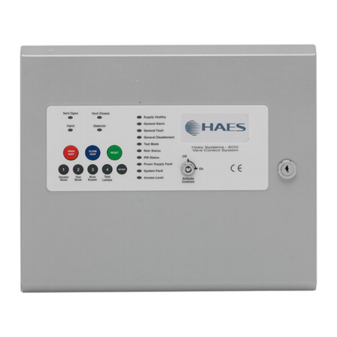
AOV is a range of single area Automatic Opening Vent control panels. The panels are available with three
different output capabilities, 3 Amp, 5 Amp & 10 Amp for controlling small, medium or larger loads.
The panels are supplied in two different enclosure sizes with the 3 Amp version in a smaller cabinet with
space for 3.2Ah batteries and the 5 & 10 Amp versions in a larger cabinet with space for 12Ah batteries.
Standard & high spec versions are available with the high spec version including additional control inputs
and outputs. See product codes and features table.
All variations are supplied in a sheet steel enclosure suitable for wall mounting with a hinged, lockable front
access door. The panels can be semi recessed using a suitable recessing bezel. Cable entry is via 20mm
knockouts located at the top and rear of the cabinet.
Different key types are used for the door lock and the ‘activate controls’ key switch. It is also possible
to enable the controls via a 4 digit code entry, if preferred. An eight button keypad is used to control the
system and allow access to the function options. The three main buttons, ‘OPEN VENT’ (red), ‘CLOSE
VENT’ (blue) & ‘RESET’ (green) being much larger and colour coded to assist the end users.
The panels are designed to control 24vdc motorised vents which use a polarity reversal to control direction.
A 1 Amp output is also provided for the control of magnetic vents or other purposes.

AOV Installation, Commissioning & Operating Manual Approved Document Ref: UI-AOV-01 Issue 7.0
3
ABOUT THIS PANEL
Quiesecent and alarm current details for standby battery calculations
Product codes and features
Input & output key
Model Standby Current Alarm Current
AOV-3 65mA 106mA
AOV-3H 75mA 116mA
AOV-5 65mA 106mA
AOV-5H 75mA 116mA
AOV-10 65mA 106mA
AOV-10H 75mA 116mA
Product Power Enclosure Size Batt Capacity Inputs Outputs
AOV-3 3 Amp 308W x 260H x 80D 3.2Ah A, S, E, F M, ACT(x1), CA, CF
AOV-3H 3 Amp 308W x 260H x 80D 3.2Ah A, S, R, P, E, F, B M, ACT(x2), CA, CF, BMS
AOV-5 5 Amp 460W x 310H x 110D 12Ah A, S, E, F M, ACT(x1), CA, CF
AOV-5H 5 Amp 460W x 310H x 110D 12Ah A, S, R, P, E, F, B M, ACT(x2), CA, CF, BMS
AOV-10 10 Amp 460W x 310H x 110D 12Ah A, S, E, F M, ACT(x1), CA, CF
AOV-10H 10 Amp 460W x 310H x 110D 12Ah A, S, R, P, E, F, B M, ACT(x2), CA, CF, BMS
Inputs Outputs
A Alarm input circuit M Magnetic vent
S Smoke detection circuit ACT Actuator
R Rain sensor CA Common alarm contacts
P PIR sensor CF Common fault contacts
E External control switch BMS BMS 0-10v status
F Firemans override
BBMS 0-10v control

AOV Installation, Commissioning & Operating Manual Approved Document Ref: UI-AOV-01 Issue 7.0
4
ABOUT THIS PANEL
Vent Control System
57mm 80mm
260mm
308mm
250mm
300mm
AOV-3 CABINET

AOV Installation, Commissioning & Operating Manual Approved Document Ref: UI-AOV-01 Issue 7.0
5
ABOUT THIS PANEL
AOV-5/10 CABINET
95mm 110mm
310mm
455mm
300mm
450mm
Vent Control System

AOV Installation, Commissioning & Operating Manual Approved Document Ref: UI-AOV-01 Issue 7.0
6
ABOUT THIS PANEL
CIRCUIT BOARDS
AOV panels comprise of two circuit boards, a master PCB and a display & controls PCB
+ -
12V
- -
PSU10A
+ + + -+ -
+ -
+ - + - + - + -
C NC NO C NC NO IP OP
OP CLCOM ON OFFCOM
COM
ALARM FAULT AUX ACT 1
+ -
ACT 2 INPUT DETECTOR RAIN PIR 0/10V
BATTERY VENT CONT FIREMAN SW
1 2 3 4 5 6 7
ON
1 2 3 4 ENTER
OPEN
VENT
CLOSE
VENT RESET
1 2 3 4 ENTER
OPEN
VENT
CLOSE
VENT RESET
TPCA016V(H) Master PCB
TPCA02-AOV - LED Display & Controls PCB for AOV-3 control panels
TPCA03-AOV - LED Display & Controls PCB for AOV-5/10 control panels

AOV Installation, Commissioning & Operating Manual Approved Document Ref: UI-AOV-01 Issue 7.0
7
ABOUT THIS PANEL
MAIN PCB TERMINALS (drawing shows high spec version with all available inputs and outputs tted)
28v input from power supply module (max 10A)
Common alarm VFCO relay. Unfused max 3A @ 30v dc
Common fault VFCO relay maintained (fail safe). Unfused max 3A @ 30v dc
0/10v control input/output
100mA @ 12v dc supply output for PIR
Magnetic vent output (maintained). Max 1A @ 28v dc
Conventional/Twin Wire smoke detector input
Actuator motor drive outputs, fused @ 10A (subject to PSU ratings)
4K7 Ω
470 Ω Trigger alarm input
4K7 Ω
470 Ω Rain sensor input
PIR sensor input
Vent
control
switch
inputs
Firemans
switch
inputs
+ -
12V
- -
PSU10A
+ + + -+ -
+ -
+ - + - + - + -
C NC NO C NC NO IP OP
OP CLCOM ON OFFCOM
COM
ALARM FAULT AUX ACT 1
+ -
ACT 2 INPUT DETECTOR RAIN PIR 0/10V
BATTERY VENT CONT FIREMAN SW
1 2 3 4 5 6 7
ON

AOV Installation, Commissioning & Operating Manual Approved Document Ref: UI-AOV-01 Issue 7.0
8
ABOUT THIS PANEL
General Specication
Enclosure Steel IP30. Epoxy powder coated Interpon Radon, silver grey
Temperature range -5 deg C to +40 deg C max RH 95%
Number of conventional/Twin Wire detection circuits 1
Conventional/Twin Wire detector compatibility Apollo: S65, Orbis. / Hochiki CDX. / Nittan EV
TECHNICAL SPECIFICATION
Electrical Specication Inputs & Outputs - TPCA016-V
Cabling Fire resistant screened cable, minimum
size 1mm2. Max cable length 1Km (20
Ohm). FireBurn, FP200 or equivalent
(max capacitance 1uF, max inductance 1
millihenry).
Suitable cable glands must be used.
Terminal capacity 0.5mm2to 2.5mm2solid or stranded wire.
PSU Input, 10A - - + + 28vdc supply input. Diode protected for
reversal and independent short circuit.
Max current 10 amps.
Max input current 10 amps. Input voltage
22vdc to 32vdc.
Common Alarm Relay Alarm relay contact. Clean C/O.
Max 3A @ 30vdc.
Unfused.
Common Fault Relay Maintained fault relay contact. Clean
C/O. Max 3A @ 30vdc.
Unfused.
Aux + - Maintained magnetic vent output, 28v
dc. Max 1 amp.
Fused 1 amp, 20mm glass quick blow
fuse.
ACT1 + - Dual polarity reversal actuator drive
outputs, 28v dc. Max 8 amps.
Fused 10 amp, 20mm glass quick blow
fuse.
Input + - Alarm activating input, 470R alarm. 4K7
Ohm 5% 0.25W EOL resistor.
Monitoring current limit 14mA, unfused.
Detector + - Fire alarm zone circuit. Conventionally
wired detection circuit or Twin Wire
combined detection / sounder circuit.
4K7 Ohm 5% 0.25W EOL resistor.
Monitoring current limit 50mA, fused
@ 500mA. Typical max load 22 alarm
devices @ 18mA each.
12v + - 12v dc supply output for PIR power. 12v dc, fused @ 100mA resettable fuse.
Additional Inputs & Outputs on High Spec Version - TPCA016-VH
ACT2 + - Dual polarity reversal actuator drive
outputs, 28v dc. Max 8 amps.
Fused 10 amp, 20mm glass quick blow
fuse.
Rain + - Rain sensor signal input. 470R alarm.
4K7 Ohm 5% 0.25W EOL resistor.
Monitoring current limit 14mA, unfused.
PIR + - PIR input N/C contacts. Alarm = 8K, 4K7
Ohm 5% 0.25W EOL resistor.
Monitoring current limit 14mA, unfused.
0/10v Input Positional voltage input, 10% steps of
motor time.
Max 10v dc, 75K Ωimpedance.
Com Common 0v output. Reference ground.
0/10v Output Positional voltage output, 10% steps. 680R impedance, max 10v dc 2mA. Max
20K Ωload.
AOV Installation, Commissioning & Operating Manual Approved Document Ref: UI-AOV-01 Issue 7.0
9
ABOUT THIS PANEL
POWER SUPPLY MODULES
Power Supply Specications - PSM3-24 (AOV-3)
Mains supply 230vac +10% -15% 50Hz 1.2A
Mains supply fuse 4 Amp (F4A 250V) Not accessible
Power supply rating 3 Amp incl battery charge Max shared load 3A
Power supply output voltage 22-27.6 vdc Set for batt charge O/P 27.3v
Maximum ripple 120mV p-p.
Min/max battery size and type 1.2Ah/3.2Ah x 2 12volt VRLA
Yuasa NP range
Battery charging voltage 27.3 nom dc
Battery charging output current 630mA Current limited 10 Ohms
Max current drawn from batteries 10 Amps. Battery fuse 10A HBC 20mm
Power Supply Specications - PSM5-27 (AOV-5)
Mains supply 230vac +10% -15% 50Hz 0.8A
Mains supply fuse 3.15 Amp (F3.15A 250V) Not accessible
Power supply rating 5 Amp incl battery charge Max shared load 5A
Power supply output voltage 25.7-29.7 vdc Set for batt charge O/P 27.3v
Maximum ripple 150mV p-p.
Min/max battery size and type 3.2Ah/12Ahr x 2 12volt VRLA
Yuasa NP range
Battery charging voltage 27.3 nom dc
Battery charging output current 630mA Current limited 10 Ohms
Max current drawn from batteries 10 Amps. Battery fuse 10A HBC 20mm
Power Supply Specications - PSM10-27 (AOV-10)
Mains supply 230vac +10% -15% 50Hz 1.5A
Mains supply fuse 6.3 Amp (F6.3A 250V) Not accessible
Power supply rating 10 Amp incl battery charge Max shared load 10A
Power supply output voltage 26-31.5 vdc Set for batt charge O/P 27.3v
Maximum ripple 200mV p-p.
Min/max battery size and type 3.2Ah/12Ahr x 2 12volt VRLA
Yuasa NP range
Battery charging voltage 27.3 nom dc
Battery charging output current 630mA Current limited 10 Ohms
Max current drawn from batteries 10 Amps. Battery fuse 10A HBC 20mm

AOV Installation, Commissioning & Operating Manual Approved Document Ref: UI-AOV-01 Issue 7.0
10
ABOUT THIS PANEL
V+
V-
E
N
L
24v +ve output
O/P Voltage adjust
(default setting 27.3v at 20oC)
24v -ve output
Earth
Neutral
Live
Mains input
AOV-3 - 3 AMP POWER SUPPLY MODULE

AOV Installation, Commissioning & Operating Manual Approved Document Ref: UI-AOV-01 Issue 7.0
11
ABOUT THIS PANEL
AOV-5/10 - 5 & 10 AMP POWER SUPPLY MODULE
+V -V N L
Live
Neutral
Earth
Mains Input
To -ve on TPCA016
To +ve on TPCA016
Output Voltage Adjust
(default setting 27.3v @ 20oC)

AOV Installation, Commissioning & Operating Manual Approved Document Ref: UI-AOV-01 Issue 7.0
12
PANEL FUNCTIONS
CIRCUIT DESCRIPTION/FUNCTIONS
PSU 10A - - + +
28v dc input from power supply module. Maximum input current, 10 Amps.
ALARM C NC NO
Common alarm changeover relay contacts. Activate when an alarm condition (470R) exists on the input
or detector circuit.
FAULT C NC NO
Common fault signal changeover relay contacts. Normally energised (failsafe) contacts, change over when
any fault is active on the panel or in the event of total power loss.
AUX + -
A maintained magnetic vent 28v output. Switches off to release magnet in the alarm condition. The output
can be inverted using DIL switch 2 on the main PCB. The 0/10v BMS input does not affect the operation
of this output.
ACT1 + - / ACT2 + -
Fused motor drive outputs, not normally powered. Operated for a congurable time period of 10 to 120
seconds. The default setting is 30 seconds, this should be set to the time period required to open/close
the vent fully. Polarity is reversed for vent closure. Both outputs, when tted, always operate fully.
On commissioning the vent should be set to the fully closed position prior to connection. The actuator
outputs may be changed to a continuous, maintained operation using DIL switch 3, ‘ACT POWER’.
++
+
-
-
-
AUX
+
-
ACT 1
DC Magnet
Back EMF
Diode
Polarity Controlled
Actuator, 24v dc

AOV Installation, Commissioning & Operating Manual Approved Document Ref: UI-AOV-01 Issue 7.0
13
PANEL FUNCTIONS
INPUT + - (NON LATCHING)
Alarm signal input from a remote contact. Monitored for open and short circuit faults, 4K7 end of line
monitoring resistor. Alarm signal requires a 470 Ω impedance. Can be programmed to accept a short
circuit as alarm input and latching mode (see programming details).
DETECTOR + -
Conventional/Twin Wire re alarm zone circuit. Monitored via a 4K7 end of line resistor. Up to 20 detectors
may be used on this circuit, these may use schottky diode bases for detector removal monitoring, assuring
that if a detector is removed, other devices on the cable are still functional.
The circuit can be used in ‘Twin Wire’ mode by selection of DIL switch 4 on the main PCB. This allows use
of 24v alarm sounders in reverse polarity on this circuit. Note: In this mode the detectors require special
‘Sav-Wire’ bases.
An alarm on the detector circuit will activate the vent outputs in the same way as the activation input.
Some programming options are available for this circuit, please refer to the programming and set up
section.
RAIN + - (only available on the high spec versions)
Signal input from rain sensors. Typically a rain sensor will have a closing contact alarm signal and may
require a 12v supply which can be taken from the 12v output in the panel. The input requires a 470 Ω
impedance to trigger. The rain signal will close a manually opened vent but will not override an alarm signal
status.
+ -
TRIGGER C NC NO
470Ω
4K7Ω
Trigger Input
470R
4K7
Rain
Sensor
+
+
-
-
Rain
Input
12v O/P

AOV Installation, Commissioning & Operating Manual Approved Document Ref: UI-AOV-01 Issue 7.0
14
PANEL FUNCTIONS
PIR + - (only available on the high spec versions)
The PIR input is available to monitor a typical security type PIR with N/C alarm and tamper contacts. When
operated the PIR alarm prevents the vent from closing, to guard against entrapment injury.
The PIR should be mounted in accordance with the manufacturers instructions to detect presence in the
vicinity of the entrapment risk.
0/10V (only available on the high spec versions)
Designed for interfacing with control systems using 0/10 volt proportional control signals.
IP Accepts 0/10 volt (dc) signal in 1 volt steps per 10%. Vent position is determined by running
time, which by default is 30 seconds, i.e. 10% = 3 seconds running time, 50% = 15 seconds
etc.
COM This is 0 volts common reference for 0/10V input & output
OP This output represents the position of the vent according to the time run. Provides feed back
of the 0/10V input status and vent positional information.
12V + -
12 volts dc supply for PIR or general purpose use. Max continuous rated load 100mA.
FIRMANS SW
Input for 3 way remans control switch.
ON Activates the vent output (fully open vent)
COM Common 0v reference
OFF Disables vent operation (regardless of status)
AUTO (neither input grounded) Vent follows panel automatic control
4K7
+
+
-
-
+
-
PIR
12v O/P
4K7
EOL
12v input
PIR Unit
Alarm Tamper
ON
COM
OFF Firemans
3 way switch

AOV Installation, Commissioning & Operating Manual Approved Document Ref: UI-AOV-01 Issue 7.0
15
PANEL FUNCTIONS
CABLE TYPES & LIMITATIONS
CABLING
CABLE LENGTHS
MAINS PROVISION
To comply with EMC (Electro Magnetic Compatibility) regulations and to reduce the risk of electrical
interference in the system wiring, we recommend the use of screened cables throughout the installation.
Acceptable, commonly available, screened cables, which can be used on both the sounder and detector
circuits include, NoBurn™ FP200™, Firetuff™, Firecel™, MICC (Pyro™) or any other cable complying with
BS 6387 categories C, W, Z.. Refer to BS 5839 pt1 clause 26 for detailed information on cables wiring
and interconnections.
Suitable cables should be brought into the cabinet using the knockouts provided via a suitable cable gland
recommended for use with that cable. The screen or drain wire of circuits should be bonded to earth at
one location only, and should be continuous throughout the circuit. Drain wires should be terminated in the
cabinet using the earthing terminal provided.
The maximum recommended cable length for a zone or sounder circuit is 1Km. This, however, is highly
dependant on the number and type of devices connected.
If in doubt, cable load and resistance calculations should be undetaken to ensure devices are working
within specied limits.
The mains supply to the control panel should be hard wired, using suitable three core cable (no less
than 1.0 mm² and no more than 2.5mm²) or a suitable three conductor system that meets the appropriate
national wiring regulations. The panel should be fed from an isolating switched fused spur, supplied directly
from the Main Distribution Board, fused at 3A. This should be secure from unauthorised operation.
As an alternative to a switched fused spur, an appropriately fused double pole isolating device may be
used providing it meets the appropriate national wiring regulations.
BATTERY + -
Connections for 24v VRLA batteries
VENT CONT
Vent control inputs for manual operation of vents via seperate 3 way control switch.
OP Open vent
COM Common 0v reference for switching inputs
CL Close vent
OP
COM
CL
Open Vent
Close Vent

AOV Installation, Commissioning & Operating Manual Approved Document Ref: UI-AOV-01 Issue 7.0
16
PANEL FUNCTIONS
DETECTOR CIRCUIT CONVENTIONAL SYSTEM SCHEMATIC
REMOTE INDICATOR
RIL58
+
_
4K7 OHM
END OF LINE
RESISTOR
-
+
DETECTOR
-
R
L1
L1
L2
IN OUT
-
R
L1
L1
L2
IN OUT
-
R
L1
L1
L2
IN OUT
APOLLO S65 BASE
45681-201
APOLLO S65 BASE
45681-201
APOLLO S65 BASE
45681-201
MANUAL CALL POINT
MCP1A-R-470
1234
__+ +
470

AOV Installation, Commissioning & Operating Manual Approved Document Ref: UI-AOV-01 Issue 7.0
17
PANEL FUNCTIONS
DETECTOR CIRCUIT TWIN WIRE SYSTEM SCHEMATIC
-VE
E
R+
R+
R-
R-
REMOTEINDICATOR
RIL58
+
_
Typical Twin Wire
Circuit Wiring
4K7 OHM
END OF LINE
RESISTOR
Note:
On a Twin Wire circuit
the sounders are connected in reverse polarity
to the detectors and call points
Note:
Detector circuit configuration is set to
‘Conventional’ by default. ‘Twin Wire’
mode must be set using DIL switch 4
on main PCB.
-
+
DETECTOR
APOLLO TWIN WIRE BASE
45681-206
APOLLO TWIN WIRE BASE
45681-206
TWIN WIRE CALL POINT
MCP1B-R-TW
TWIN WIRE CALL POINT
MCP1B-R-TW
1234
__+ +
470
1234
__+ +
470
-VE +VE
MOTORISED BELL
POLARISED
ELECTRONIC SOUNDER
POLARISED
+VE
+VE -VE
-VE +VE
1 2 3 4 5 6 7
ON

AOV Installation, Commissioning & Operating Manual Approved Document Ref: UI-AOV-01 Issue 7.0
18
INSTALLATION
SAFETY
Suppliers of articles for use at work are required under section 6 of the Health and Safety at Work Act 1974
to ensure as reasonably as is practical that the article will be safe and without risk to health when properly
used. An article is not regarded as properly used if it is used “without regard to any relevant information or
advice” relating to its use made available by the supplier.
This product should be installed, commissioned and maintained by, or under the supervision of, competent
persons according to good engineering practice and,
(i) BS 7671 (IEE wiring regulations for electrical installations)
(ii) Codes of Practice
(iii) Statutory requirements
(iv) Any instructions specically advised by the manufacturer
According to the provisions of the Act you are therefore requested to take such steps as are necessary to
ensure that any appropriate information about this product is made available by you to anyone concerned
with its use.
This equipment is designed to be operated from 230V AC 50/60 Hz mains supplies and is of Class I
construction. As such it must be connected to a protective earthing conductor in the xed wiring of the
installation. Failure to ensure that all conductive accessible parts of this equipment are adequately bonded
to the protective earth will render the equipment unsafe.
This equipment must only be installed and maintained by a suitably skilled and technically
competent person.
THIS IS A PIECE OF CLASS 1 EQUIPMENT AND MUST BE EARTHED
Installation of the panel should only be carried out by qualied personnel. The electronic components
within the panel can be damaged by static charge. Suitable precautions must be taken when handling
circuit boards. Never insert or remove boards or components, or connect cables, with the mains power
on or batteries connected.
Equipment Guarantee
This equipment is not guaranteed unless the complete system is installed and commissioned in accordance with the laid
down national standards by an approved and competent person or organisation.
This product has been manufactured in conformance with the requirements of all applicable EU Council
Directives
This manual suits for next models
6
Table of contents
Other Haes Control Panel manuals

Haes
Haes ELAN HS-5000 Series User manual

Haes
Haes Excel-32 Series User manual

Haes
Haes AlarmSense Guide

Haes
Haes SZAOV Guide

Haes
Haes AlarmSense PLUS User manual

Haes
Haes ESENTO MARINE Guide

Haes
Haes MZAOV-1001 Guide

Haes
Haes FCPTEC-HS-4200 Guide

Haes
Haes FUSION 0832-CPD-1431 User manual

Haes
Haes Excel-EN Guide
Popular Control Panel manuals by other brands

NAPCO
NAPCO Gemini GEM-P1664EX datasheet

Harvia
Harvia Xenio CX004WIFI Instructions for installation and use

UniPOS
UniPOS IFS7002 instruction manual

GE
GE IC754CSF15CTD Hardware user's guide

Arrowhead Alarm Products
Arrowhead Alarm Products ELITE SX-2 Installation & programming guide

Tormach
Tormach pathpilot installation guide