manuals.online logo
Brands
  1. Home
  2. •
  3. Brands
  4. •
  5. hager
  6. •
  7. Controllers
  8. •
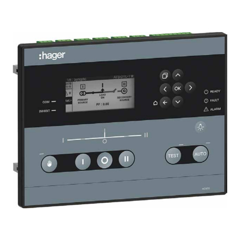
  9. hager HZI855 User manual

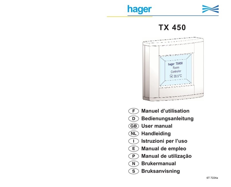
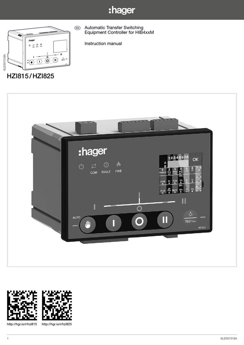
hager HZI855 User manual

160
220
Clic !
A
C
6,4
R 6,25
3
39 ±0,3
22,05
15,5 ±0,5
135°
2
8 ±0,1
6LE007315Ab
551103B / Printing size: 3x A4 / Recto-verso / Black / 90g/m² / Final size A5
Preliminary operations
Check the following upon delivery and after removal
of the packaging:
• Packaging and contents are in good condition.
• The product reference corresponds to the order.
• Contents should include:
- 1 HZI855 ATSE controller
- 4 door mounting screws
- 4 backplate mounting feets
• Accessory: IP65 gasket: ref. HZI501
This Quick Start is intended for personnel trained in
the installation and commissioning of this product.
For further details refer to the product instruction
manual available on www.hager.com.
This product must always be installed and
commissioned by qualied and approved personnel.
Maintenance and servicing operations should be
performed by trained and authorised personnel.
Do not handle any control or power cables connected
to the product when voltage may be, or may become
present on the product, directly through the mains or
indirectly through external circuits.
Always use an appropriate voltage detection device
to conrm the absence of voltage.
Ensure that no metal objects are allowed to fall in the
cabinet (risk of electrical arcing).
Failure to observe good enginering practises as well
as to follow these safety instructions may expose the
user and others to serious injury or death.
Installation and commissioning controller
zAutomatic Transfer Switching
Equipment Controller
HZI855
551103B
Risk of electrocution, burns or injury to
persons and / or damage to equipment.
Risk of damaging the device In case the
product is dropped or damaged in any way it is
recommended to replace the complete product.
6LE007315Ab1
160
220
A
0,1 Nm
PH1
D
C
mm
Protection IP30 as standard.
For IP65, use reference HZI501
as accesory.
3P + N 1P + N
2P + N
2P
3P
L1 L2 L1 L2L3
L1 L2 L1 L2L3
NL1 N
N
6LE007315Ab2
160
220
240 64
49
180
Type of networks
Metering and sensing detail
Networks
mm
Loss of neutral: will be detected in all cases except
for balanced networks with balanced loads.
In Breaker mode: the use of undervoltage release
(see wiring diagram) can prevent this situation.
Power Supply:
The HZI855 controller is Self-powered from the voltage sensing of any
available source, and may also be powered (as a backup from saved
source) from the DC auxiliary power input (24 VDC).
Dual Power Supply / Sensing
The HZI855 controller will be automatically supplied from the voltage
sensing connectors of both sources thanks to an internal DPS (dual power
supply) module that in case main source failure, will immediately switch to
the secondary source supply the device.
NOTE: The nominal auxiliary power supply feeding the sensing terminals
must be within the limits of 88 ➡576 VAC.
NOTE: The HZI855 must include a SCPD such
as fuses on each phase of the voltage sensing
control wiring.
1A gG fuses are recommended.
NETWORK TYPE
1P+N 2P 2P+N 3P 3P+N 3P+N / 1P+N
Source
1
1 phase
2 wire
2 phase
2 wire
2 phase
3 wire
3 phase
3 wire
3 phase
4 wire
3 phase
4 wire
Source
2
1 phase
2 wire
301 302 201 202101
HZI812
102
LN LNLN
4 A 4 A
12
L1
L2
L3
N
L1
L2
L3
N
230/400 V230/400 V
HIB4xxM
11 14 12 21 24 22 31 34 32 41 44 42 51 54 52 61 64 62
71 72 73 74 75 76 70 82 81
OUT 1 OUT 2 OUT 3 OUT 4 OUT 5 OUT 6
USB
IN1 IN2 IN3 IN4 IN5 IN6 COM + -
INPUTS
N
SOURCE 1
L3 L2 L1 N
SOURCE 2
L3 L2 L1
RS485
NC - +
312 313 314 315 316 317 63A 64A 24 14 04 13
Ctrl OFF I I
I I
I
I
0
0
C
C
301 302
1 A 1 A
*
Dimensions HZI855 and HIB4xxM
for network / network application type
for network / genset application type
301 302 201 202101
HZI812
102
LN LNLN
4 A 4 A
1
L1
L2
L3
N
L1
L2
L3
N
230/400 V 230/400 V
HIB4xxM
11 14 12 21 24 22 31 34 32 41 44 42 51 54 52 61 64 62
71 72 73 74 75 76 70 82 81
OUT 1 OUT 2 OUT 3 OUT 4 OUT 5 OUT 6
USB
IN1 IN2 IN3 IN4 IN5 IN6 COM + -
INPUTS
N
SOURCE 1
L3 L2 L1 N
SOURCE 2
L3 L2 L1
RS485
NC - +
312 313 314 315 316 317 63A 64A 24 14 04 13
Ctrl OFF I I
I I
I
I
0
0
C
C
301 302
1 A 1 A
GE
Start
*
Default conguration for Inputs and Outputs for "HIB4xxM" mode:
IN1: Switch is in position 1
IN2: Switch is in position 2
IN3: Switch is in position 0
IN4: Inhibit
IN5: Manual restransfer
IN6: RTSE in manual
OUT1: Order to switch in position 1
OUT2: Order to switch in position 2
OUT3: Order to switch in position 0
OUT4: S1 Available
OUT5: S2 Available
OUT6: Order to start Genset
* The use of this input is optional, when used IN6 should be congured
to "COVER OPEN" in mode "NC".
This conguration is dened with source I as the priority source.
This diagram covers most application cases, the inputs and outputs
are congured by default for this installation.
For single phase networks,
the neutral has to be
bridged from N to L2
6LE007315Ab3
HXA021H
AX contact
230 Vac
HXA014H
UV coil
230 Vac
4 2 1
1
HXA021H
AX contact
230 Vac
2 4 1
HXA024H
AL contact
230 Vac
2 4
HXA014H
UV coil
230 Vac
12
L1
L2
L3
N
L1
L2
L3
N
230/400 V 230/400 V
mechanical
interlock
HXx042H
MCCB 1 MCCB 2
P1 OFF ON C P2 E
Motor 1
230 Vac
supply
electrical
interlock
11 14 12 21 24 22 31 34 32 41 44 42 51 54 52 61 64 62
71 72 73 74 75 76 70 82 81
OUT 1 OUT 2 OUT 3 OUT 4 OUT 5 OUT 6
USB
IN1 IN2 IN3 IN4 IN5 IN6 COM + -
INPUTS
N
SOURCE 1
L3 L2 L1 N
SOURCE 2
L3 L2 L1
RS485
NC - +
HXx042H
P1 OFF ON C P2 E
Motor 2
230 Vac
supply
emergency
stop
1 A1 A
ESC427ESC427
ESC427ESC126
6 A 6 A
HZI855 with MCCB
for network / network application type
HXA021H
AX contact
230 Vac
HXA014H
UV coil
230 Vac
4 2 1
1
HXA021H
AX contact
230 Vac
2 4 1
HXA024H
AL contact
230 Vac
2 4
HXA014H
UV coil
230 Vac
12
L1
L2
L3
N
L1
L2
L3
N
230/400 V 230/400 V
mechanical
interlock
HXx042H
MCCB 1 MCCB 2
P1 OFF ON C P2 E
Motor 1
230 Vac
supply
electrical
interlock
11 14 12 21 24 22 31 34 32 41 44 42 51 54 52 61 64 62
71 72 73 74 75 76 70 82 81
OUT 1 OUT 2 OUT 3 OUT 4 OUT 5 OUT 6
USB
IN1 IN2 IN3 IN4 IN5 IN6 COM + -
INPUTS
N
SOURCE 1
L3 L2 L1 N
SOURCE 2
L3 L2 L1
RS485
NC - +
HXx042H
P1 OFF ON C P2 E
Motor 2
230 Vac
supply
emergency
stop
1 A1 A
ESC427ESC427
GE
Start
6 A 6 A
HZI855 with MCCB
for network /genset application type
Note: indicated references are used for MCCB x250/P250 and x630/P630.
Default configuration for Inputs and Outputs for "Breaker" mode:
IN1: Breaker 1 is in position ON
IN2: Breaker 2 is in position ON
IN3: Breaker 1 is in position OFF
IN4: Breaker 2 is in position OFF
IN5: Breaker 1 is in position TRIP
IN6: Emergency stop
OUT1: Order to close Breaker 1
OUT2: Order to close Breaker 2
OUT3: Order to open Breaker 1
OUT4: Order to open Breaker 2
OUT5: NONE
OUT6: Order to start Genset
This conguration is dened with source I as the priority source.
This diagram covers most application cases, the inputs and outputs
are congured by default for this installation, the actions of the
controller will be:
- In the event of neutral loss from source I: the undervoltage coil
will trip the circuit breaker for source I making it unavailable (ALarm
contact on input 5) to switch to secondary source II.
- In the event of tripping via the emergency stop button: the
undervoltage coil will trip the circuit breaker of the source I making it
unavailable (ALarm contact on input 5) BUT the control ler will switch
to " total inhibition ”(input 6 activated), that is to say that the load will
no longer be supplied without manual intervention on the controller in
order to acknowledge this fault.
After acknowledgment, the controller will switch to priority source I if
available, otherwise to secondary source II.
6LE007315Ab4
HZI855
Optional Aux. Supply
24V (6W)
82 70 76 75 74 73 72 71 6164
OUT 6
LATCHING RELAY OUTPUTS (NC-NO-C) OUTPUTS (NC-NO-C)INPUTS
OUT 5
62 515452
IN1IN2IN3IN4IN5IN6C
81
Config USB
OUT 4
414442
OUT 3
313432
OUT 2
212422
OUT 1
111412
ATSE Controller with communication
ALL OUT: AC1– AC general use Ie: 8A Ue: 250V~ 50/60Hz 1.6kW AC15 – AC pilot duty Ie:2A Ue:250V~ 50/60Hz 175W DC1 – DC general use Ie:5A 24V 120W
N°/ SN:ZRSSAAXXLYYYYFFFFFFFFI Made in France
Test level ; Between SOURCES
When type tested with IEC 60947-6-1 RTSE
TighteningTorques:
RS485:0.22-O.25Nm/1.9-2.2lb.in
All others:0.5-0.6Nm/4.4-5.3lb.in
OperatingTemperature:
-30/70°C
RS485120Ω
ON
OFF
Product
Consumption
on sources
10VA
Hager Electro SAS
BP3
67215 OBERNAICEDEX FRANCE
Notice:http://hgr.io/r/hzi855
IEC 60947-6-1IEC61010-2-201GB/T 14048.11
appendixC
8kV
Voltage Sensing220-227V~ L/N -30 +20% 400-480V~ L/L’ -30+20%
50-60Hz50-60Hz50Hz
110-227V~ L/N -30+20% 190-480V~ L/L’ -30+20% 220V~ L/N -30 +20% 380V~ L/L’ -30 +20%
4kV
OvervoltageCat.
U imp
Frequency
IIIIIIIII
Controller wiring
5. Optional Aux. Supply 24 VDC.
6. Programmable INPUTS.
7. Programmable OUTPUTS.
8. Latching relays.
9. Cong USB.
1. Voltage sensing source 1.
2. Voltage sensing source 2.
3. RS485.
4. RTC battery
TYPE TERMINAL
N° DESCRIPTION BY DEFAULT CONFIGURATION CHANGES WHEN CHANGING
RTSE TECHNOLOGY CHARACTERISTICS RECOMENDED CROSS
SECTION
Breakers HIB4xxM Contactors
Inputs
71 IN1: programmable input Breaker 1 is in position ON Switch is in position 1 Contactor 1 is in position ON
Do not connect to any
power supply from
terminal 70 common
point.
Congurable type NO or
NC - NO by default
1.5-2.5 mm²
Tightening torque
0.5-0.6 Nm
4.4-5.3 Lb.in
72 IN2: programmable input Breaker 2 is in position ON Switch is in position 2 Contactor 2 is in position ON
73 IN3: programmable input Breaker 1 is in position OFF Switch is in position 0 -
74 IN4: programmable input Breaker 2 is in position OFF Inhibit -
75 IN5: programmable input Breaker 1 is in position TRIP Manual retransfer -
76 IN6: programmable input Emergency stop RTSE in manual -
70 Common point for inputs
Outputs
Logic Impulse Impulse Maintained
Dry contacts
8 A / 277 VAC 50/60 Hz
5 A / 24 VDC
Congurable type NO or
NC - NO by default
1.5-2.5 mm²
Tightening torque
0.5-0.6 Nm
4.4-5.3 Lb.in
12/14/11 OUT1: programmable output Order to close Breaker 1 Order to switch in
position 1 Order to close Contactor 1
22/24/21 OUT2: programmable output Order to close Breaker 2 Order to switch in
position 2 Order to close Contactor 2
32/34/31 OUT3: programmable output Order to open Breaker 1 Order to switch in
position 0 -
42/44/41 OUT4: programmable output Order to open Breaker 2 S1 Available -
Latching
relays
Logic Impulse Impulse Maintained
52/54/51 OUT 5: genset start relay / programmable output - S2 Available -
62/64/61 OUT 6: genset start relay / programmable output Order to start Genset Order to start Genset -
Serial
connection RS485
Connection RS485
-: negative terminal of RS485 bus
+: positive terminal of RS485 bus
NC: ground
- - - RS485 bus insulated
Modbus cable 25 m = HTG485H
LiYCY sheilded twisted pair 0.14
to1.5 mm² /
Tightening torque
0.22-0.25 Nm
1.9-2.2 Lb.in
Aux power
supply 81/82 -: negative terminal for aux supply
+: positive terminal for aux supply - - - 12-24 VDC
Tightening torque
0.5-0.6 Nm
4.4-5.3 Lb.in
Top viewBottom view
Cabling Output relays 1-4 Cabling Output Latching relays 5 & 6
Controller cong STATE (relay)
Normally
Open (NO) (11-14)
Normally
Closed (NC) (11-12)
Normally
Open (NO) (61-64)
Normally
Closed (NC) (61-62)
Output congured as NO
NO by default
OFF (not active) Open Closed Open Closed
ON (activated by rmware) Closed Open Closed Open
Controller not supplied Open Closed Closed* Open*
Output congured as NC OFF (not active) Closed Open Closed Open
ON (activated by rmware) Open Closed Open Closed
Controller not supplied Open Closed Closed* Open*
* HZI855 controller includes two bi-stable relays with backup energy, when the controller loses all sources of power supply outputs 5 and 6 will automatically activate (NO contact will close and
NC contact will open). This is a safety feature designed to ensure power availability to the load in Main-Genset or Genset-Genset application by forcing generators to start in case of total power
loss. It is highly recommended to congure the outputs 5 and 6 to take benet from this function.
Menus & programming
6LE007315Ab5
Visualization
- Short press on this
button to cycle the
dashboards.
- Short press on this button to go back one level.
- Long press to access the menus.
To access to certain functions, you may be asked for a password.
By default, this is 1000.
Interface
1. Manual operation buttons and indicator.
2. Test button and indicator.
3. Automatic button and LED indicator.
4. Lamp test button.
5. Power, Fault and alarm LED.
6. Navigation buttons.
7. Change dashboard.
8. LCD display.
9. LED COM & Inhibit.
10. Source and switch synoptic.
For advanced conguration go to parameters menu.
SMART WIZARD CONFIG:
When powered for the rst time the controller will prompt the user to congure using the wizard.
To access the wizard input code 1000 then the conguration will go as follow:
* The maintenance dashboard allows users to visualise all maintenance alarms configured.
2 STATUS
<2.1> STAT. / STATE
<2.2> SYNC / SYNC
1 MIMIC
<1.1> STAT. / SOURCES
<1.2> MET. / METERING
<1.3> INFO. / INFO
5 ALARMS
<5.1> ACT / ACTIVE
<5.2> FIN / FINISHED
6 I/O
<6.1> IN / INPUTS
<6.2> OUT / OUTPUTS
3 METERING
<3.1> SYS / SYS
<3.2> V / V
<3.3> U / U
<3.4> F / F
4 TIMERS
<4.1> RUN / RUNNING
<4.2> S1 / SOURCE 1
<4.3> S2 / SOURCE 2
<4.4> OPT / OPTIONS
<4.5> TOX / TEST
<4.6> EOX / EXT TEST
7 MAINTENANCE*
<7.1> AL1
<7.2> AL2
<7.x> ALx
LANGUAGE
DATE AND TIME
SOURCES
INSTALLATION
PRODUCT
NAME
COMMUNICATION
RS485
SCHEDULER
GENERAL PARAMETERS
CUSTOM 1
STATISTICS
CYCLES
OPERATIONS
OPERATING HOURS
SOURCE 1
SOURCE 2
GENSET 1
GENSET 2
BREAKER
CONTROL
MODE / POSITION
TEST
MANUAL RETRANSFER
MAIN MENU
CONTROL
LOG
STATISTICS
GENSET SCHEDULER
PARAMETERS
SPECIFIC FUNCTIONS
MAINTENANCE
ABOUT
LOG
EVENT LOG
ALARM LOG
FAULTS
NETWORK
AUTODETECT.
SETUP
APPLICATION
OP RANGE S1
OP RANGE S2
DISPLAY
SCREEN
DATE AND TIME
OPTIONS
CHANGE PRODUCT NAME
SCREENSAVER TEXT
TIMERS
OPERATION
GENSET SOURCE 1
GENSET SOURCE 2
TESTS ON LOAD
TESTS OFF LOAD
I/O
INPUTS
OUTPUTS
COMMUNICATION
MODBUS ADDRESS
RS485 MODBUS
ALARMS
LOGICAL ALARMS CONFIG
MAINTENANCE ALARMS CONFIG
SYSTEM ALARMS CONFIG
PASSWORD
CHANGE OPERATOR PWD
CHANGE CONFIG PWD
CHANGE MAINTENANCE PWD
BACK
WIZARD
LANGUAGE
DATE AND TIME
SOURCES
INSTALLATION
PRODUCT NAME
COMMUNICATION RS485
PARAMETERS
NETWORK
DISPLAY
TIMERS
I/O
COMMUNICATION
ALARMS
PASSWORD
WIZARD
Hager Electro S.A.S., Boulevard d'Europe, B.P. 3, 67215 OBERNAI CEDEX, France - www.hager.com OCOM 140065Hager 10.20 6LE007315Ab6
There are several events that can cause a Fault on the controller. Unlike the alarms, the faults are not user-selectable, they will
always be considered and actions will take place as follows:
FAULT DESCRIPTION (CAUSE) ACTIONS ACKNOWLEDGE /
CLEARED
FAULT
LOG POP-UP FAULT LED OUTPUT
Unexpected
Transfer
The controller receives a
feedback/return from the
switch without sending any
order (auto or manu). Also
if loss feedback of current
position.
Mode stays the
same. Controller
will start retries if
position is unknown.
If a position is
reached, no retry
takes place.
Can also be cleared
through display or
through RST - Reset
Fault input.
Yes Yes, "Unexpected
Transfer"
BLINKS
(priority) FLT - Fault active
Failed to Transfer
Position not reached after
an order sent by controller
(auto or manu) or loss of
feedback of the new source
after sending a transfer
command.
Mode stays the
same. Controller will
start retries.
Automatically cleared
if the requested
position is reached
or cleared through
display or through
RST - Reset Fault
input.
Yes Yes, "Failed to
transfer"
BLINKS
(priority) FLT - Fault active
Max operation per
minutes reached
If the controller performs
10 operations in less
than 1 minute (by default)
(automatic or controlled/
manual)
Mode stays the
same. During a timer,
the controller will
not do or allow any
operation.
Automatic after the 1
minute (congurable
through software)
(value is dynamic).
Yes
Yes, "Max
operations per
minutes reached"
FIXED
(non-critical) FLT - Fault active
Max password
attempts reached
User tries to enter a prole
password more than X times
set in the maintenance menu
(by default 10 attempts)
Mode stays the
same. Can't enter
any password
during X time set
in the maintenance
menu (by default 2
minutes)
Automatic after
the set timeout
(maintenance mode).
Yes
Yes, "Max number
of tries reached,
please wait: X s"
FIXED
(non-critical) FLT - Fault active
Genset Failstart
Controller tries to start a
genset (as congured) and
after the genset start delay,
the genset doesn't start
(controller doesn't see the
source on)
Mode stays the
same. Genset start
relay remains active
unless other source
is available.
Automatic if genset
starts or if source is
set as Main/Utility.
Yes Yes, "Engine fail to
start"
BLINKS
(priority) FLT - Fault active
External fault
If an input is selected as
FTE - External Fault and
becomes active
Switch goes to
position 0 /center-
off directly without
timers and the mode
is set to Partial
Inhibit (genset starts
if needed).
Input mustn't be
active and reset by
user is requested
(by RST- Reset Fault
input or through
display.
Yes Yes, "External
fault"
BLINKS
(priority) FLT - Fault active
For faults with pop-up, the pop-up will be cleared when fault will be cleared or by pressing any button on the front face of the
controller. The total number of faults logged on the controller is dynamic, as the total number of “faults + alarms” is 100 (not
including the events, which are 300) and uses a FIFO ordering.
To clear Faults through the display, it is possible inside the LOG/FAULTS menu with the option “PRESS OK TO CLEAR
FAULTS”, using the congurator prole password (1000). There is also a shortcut by holding the button for 1.5s and
validating on the pop-up that appears. If the fault is still active, it will be inside the log “in progress” but the fault LED and
output will be off. If the faults are not active any more, they will be logged in the “history” log. This way to clear the fault will
be automatically proposed by the controller through a pop-up:
Trouble shooting guide
FAULTS
FAILED TO TRANSFER
1,5 s -> RESET FAULTS

Other manuals for HZI855

1

Other hager Controllers manuals

hager coviva Smartbox TKP100A User manual

hager

hager coviva Smartbox TKP100A User manual

hager 2-679-0630 User manual

hager

hager 2-679-0630 User manual

hager TX502 User manual

hager

hager TX502 User manual

hager WUT09 User manual

hager

hager WUT09 User manual

hager coviva Smartbox TKP100A Quick guide

hager

hager coviva Smartbox TKP100A Quick guide

hager HZI855 User manual

hager

hager HZI855 User manual

hager EZN005 User manual

hager

hager EZN005 User manual

hager TX502 User manual

hager

hager TX502 User manual

hager RTQ520X User manual

hager

hager RTQ520X User manual

hager TYB6.2F User manual

hager

hager TYB6.2F User manual

hager EG 001 Installation instructions

hager

hager EG 001 Installation instructions

hager TJA560 User guide

hager

hager TJA560 User guide

hager TX 206H User manual

hager

hager TX 206H User manual

hager 60060 User manual

hager

hager 60060 User manual

hager WDT030 User manual

hager

hager WDT030 User manual

hager TX 223 User manual

hager

hager TX 223 User manual

hager TYB691F User manual

hager

hager TYB691F User manual

hager coviva Smartbox TKP100A User manual

hager

hager coviva Smartbox TKP100A User manual

hager TX 450 User manual

hager

hager TX 450 User manual

hager XEVS000 Operating and safety instructions

hager

hager XEVS000 Operating and safety instructions

hager HZI815 User manual

hager

hager HZI815 User manual

hager HZI810 User manual

hager

hager HZI810 User manual

hager WUT09 User manual

hager

hager WUT09 User manual

hager TX450B User manual

hager

hager TX450B User manual

Popular Controllers manuals by other brands

2M Technology 2MGST-6 user manual

2M Technology

2M Technology 2MGST-6 user manual

Ampcontrol imac itools user manual

Ampcontrol

Ampcontrol imac itools user manual

Kelly KLS8080N user manual

Kelly

Kelly KLS8080N user manual

BFT ICARO SMART AC A2000 Installation and user manual

BFT

BFT ICARO SMART AC A2000 Installation and user manual

ETC echoflex ELED2-BCL Configuration guide

ETC

ETC echoflex ELED2-BCL Configuration guide

Athena Controls RMB/12 Configuration and operation manual

Athena Controls

Athena Controls RMB/12 Configuration and operation manual

Parker Compax3 Fluid T40 installation manual

Parker

Parker Compax3 Fluid T40 installation manual

Siemens L-828 manual

Siemens

Siemens L-828 manual

Allen-Bradley PowerFlex 70 Reference manual

Allen-Bradley

Allen-Bradley PowerFlex 70 Reference manual

Mitsubishi Electric Q Series Programming manual

Mitsubishi Electric

Mitsubishi Electric Q Series Programming manual

Rutenbeck Control Plus IP4 installation instructions

Rutenbeck

Rutenbeck Control Plus IP4 installation instructions

Fiesta BLUE EMBER GRILLS iQue Instruction manual and use

Fiesta

Fiesta BLUE EMBER GRILLS iQue Instruction manual and use

YASKAWA AO-A3 User & installation manual

YASKAWA

YASKAWA AO-A3 User & installation manual

Omron NB-series Service guide

Omron

Omron NB-series Service guide

YOKOGAWA UT321 user manual

YOKOGAWA

YOKOGAWA UT321 user manual

Philips iPlayer 3 quick start guide

Philips

Philips iPlayer 3 quick start guide

ARRI UMC-4 user manual

ARRI

ARRI UMC-4 user manual

YASKAWA A1000 Series quick start guide

YASKAWA

YASKAWA A1000 Series quick start guide

manuals.online logo
manuals.online logoBrands
  • About & Mission
  • Contact us
  • Privacy Policy
  • Terms and Conditions

Copyright 2025 Manuals.Online. All Rights Reserved.