manuals.online logo
Brands
  1. Home
  2. •
  3. Brands
  4. •
  5. hager
  6. •
  7. Controllers
  8. •
  9. hager 60060 User manual

hager 60060 User manual

60060
6LE007129A
Installation fitted with an
electronic counter
A 2-wire connection, the tele-information, connects
the load controller to the electronic counter. The
tele-information informs the load controller of any
exceedance of subscribed power in order to trigger
a load shedding cycle. This connection is not
polarized (max. distance = 100 m).
Use a 6/10 twisted pair cable.
Installation fitted with an
electromechanical counter
For this type of installation, the current
transformer that comes with the product
(part number 60005) must be connected to the
load controller.
This current transformer must be installed on the
phase that begins from the branch circuit breaker.
It informs the load controller of the total power
consumed by the installation.
When this consumption exceeds the limit set on
the load shedding threshold potentiometer, a
load shedding cycle is triggered.
Load shedding
The load controller is informed by the electronic
counter of the exceedance of subscribed power.
It will manage this excess as follows: all of
the channels are ooaded. It then relays the
channels in the following order of priority:
1. the outputs in “contact” mode or the pilot wire
outputs that are set to “comfort”
2. the pilot wire outputs that are set to “reduced”
3. the pilot wire outputs that are set to “frost
protection”.
It will perform a rotating load shed between the
outputs that have the same priority level.
The load shedding cycle is 6 minutes.
Configuring the output type
The switches 5define the type of output.
•outputs in “closing switch” mode.
To be used when the outputs
control a closing switch (C or NO).
In this mode:
- Load shedding = O = 0 V
- On = 230 V
•outputs in “opening switch” mode.
To be used when the outputs
control an opening switch (O or
NC).
In this mode:
- Load shedding = O = 230 V
- On = 0 V
•outputs in “pilot wire” mode. To
be used when the outputs control
pilot wire input devices.
In this mode:
- Load shedding = “o” signal.
- 6 compatible pilot wire sequences.
Test button
Pressing this button launches a load shedding
test. This test consists of gradually ooading
outputs 1, 2 and 3 over 30 seconds.
The LEDs flash 5 times to indicate that test mode
is now in progress, then the LED corresponding
to the ooaded channel lights up.
At the end of the test, all of the LEDs switch o.
In pilot wire mode, load shedding is taken to
be the sending of a “stop” signal, which is
understood by all of the devices equipped with a
pilot wire input.
The outputs are compatible with 6 pilot wire
sequences.
Frost protection input (terminal 1)
This input allows you to force the pilot wire
outputs in frost protection mode. You can
connect a switch, the output of your telephone
controller, etc.
GThis input only operates in “pilot wire” mode.
Programming inputs (terminals 2 and 3)
Input E1 (terminal 2) controls
output S1 (terminal 4).
Input E2 (terminal 3) controls
outputs S2 and S3 (terminals 5 and 6).
•In pilot wire mode: using these inputs, you can
connect a heating timer via the pilot wire.
•Whatever the timer instructions, the load
shedding sequence takes priority.
•In contactor mode: these inputs
allow you to force OFF
Input Position of switch 5Outputs 1.2
and 3
230 V Closing switch Off = 0 V
Opening switch Off = 230 V
0 V Closing switch On = 230 V
Opening switch On = 0 V
What to do if... ?
•One or more “output” indicator lights are flashing:
- there is a short circuit on the output (pilot
wire/phase inversion in a convector, for
example).
- There is overconsumption on this output:
check how many devices are connected
to this output and their consumption.
Call your electrician.
•The counter indicator light is flashing:
- the tele-information link is not active, check
the connection or call your power company.
Installation fitted with an electromechanical
counter: this operation is normal.
Technical features
Power supply: 230 V~ +10/-15% 50 Hz
Power consumption: < 10 W
Break capacity:
- in contact mode: 1 A/230 V~ upon call
so, for example,10 x 25 A contactors
(2 modules) for 3 outputs.
- in pilot wire mode: 60 mA/230 V~ per output.
Load shedding cycle: 6 minutes
Operating temperature: 0°C to +50°C
Storage temperature: -20 °C to +60 °C
Protection rating: IP 20
Connection capacity: flexible: 1 to 6 mm2
rigid: 1.5 to 10 mm2
z
3-output universal load controller
Operating principle
The 60060 load controller optimises your
electrical service. It manages excesses of
subscribed power, thereby helping you to keep
your electrical usage to a minimum.
It limits the power used by disrupting non-priority
circuits and prevents the branch circuit breaker
from being triggered. The 60060 is a universal
load controller.
It is suitable for all installations:
- single-phase and three-phase installations
equipped with an electronic counter
or - single-phase installations equipped with
an electromechanical counter
It is adapted to circuit load-shedding via:
- closing switches
and/or - opening switches
and/or - pilot wire.
About the product
1
Counter indicator light:
- lit = counter connection correct
- flashing = no connection to counter
- off = no power.
2
Load-shedding threshold setting (for installati-
ons fitted with an electromechanical counter).
3
Test button
4
Indicator lights for outputs 1, 2 and 3
- lit = the corresponding output is offloaded
- flashing = output error
(see What do I do if... ?) section.
5
Selection switch for output type
- installation with closing switch
- installation with opening switch
- installation with pilot wire.
3
4
1
5
test
T
C
S1 S2 S3
A
FP FP FP
40 45
55
65
75
15
25
35
20
50
30 60
80
90
10
2
6LE007129A1
FP
FP
FP
FP
FP
FP
FP
FP
FP
Hager 08.19 - 6LE007129A2 Hager Controls S.A.S., 33 rue Saint-Nicolas, B.P. 10140, 67703 SAVERNE CEDEX, France - www.hager.com
Correct Disposal of This product
(Waste Electrical & Electronic
Equipment).
(Applicable in the European Union and other European
countries with separate collection systems).
This marking shown on the product or its literature
indicates that it should not be disposed with other
household wasted at the end of its working life. To
prevent possible harm to the environment or human
health from uncontrolled waste disposal, please separate
this from other types of wastes and recycle it responsibly
to promote the sustainable reuse of material resources.
Household users should contact either the retailer where
they purchased this product, or their local government
oce, for details of where and how they can take this
item for environmentally safe recycling.
Business users should contact their supplier and check
the terms and conditions of the purchase contract. This
product should not be mixed with other commercial
wastes of disposal.
Usable throughout Europe å and in Switzerland
Hager Controls hereby declares that the device complies with
the essential requirements and other relevant provisions of
Directive 2014/53/EU.
The CE declaration is available on the:
www.hagergroup.com
3456
S3
FP
FP
N
LN
3456
S3
FP
FP
L
N
fil pilote
8910 11
2345
7
1
12
6
test
S1 S2 S3
FP FP FP
LN
E2
Compteur
électronique
E1
S3=E2
S2=E2
S1=E1
ou
1
2
T1
T
C
A
40 45
55
65
75
15
25
35
20
50
30 60
80
90
10
1- pour les installations équipées d’un
compteur électromécanique
ou
2- pour les installations équipées d’un
compteur électronique
8910 11
2345
7
1
12
6
S1 S2 S3
FP FP FP
LN
circuit 1
L
N
Compteur
électronique
fil pilote
FP
FP FP FP
ou
Option:
thermostat avec
contact inverseur
(borne repos)
circuit 2 circuit 3
L
NLN
test
T
C
A
40 45
55
65
75
15
25
35
20
50
30 60
80
90
10
T1
3456
S3
FP
L
N
N
FP
For installations fitted with an
electromecanichal counter
or
For installations fitted with an electronic
counter
Electronic
counter
or
Electronic
counter
or
circuit 2 circuit 3
circuit 1
Pilot wire
Pilot wire
Electrical connection
Outline schematic
Output configured to pilot wire Output configured to opening switch Output configured to closing switch
Example: control of a heating circuit via the pilot wire and two circuits via the opening switch
Option: thermostat
with changeover
contact (terminal
normally closed)

Other hager Controllers manuals

hager WDT030 User manual

hager

hager WDT030 User manual

hager XEVS000 Operating and safety instructions

hager

hager XEVS000 Operating and safety instructions

hager TJA560 User guide

hager

hager TJA560 User guide

hager TYB691F User manual

hager

hager TYB691F User manual

hager TX206H User manual

hager

hager TX206H User manual

hager HZI855 User manual

hager

hager HZI855 User manual

hager TYB6.2F User manual

hager

hager TYB6.2F User manual

hager HZI815 User manual

hager

hager HZI815 User manual

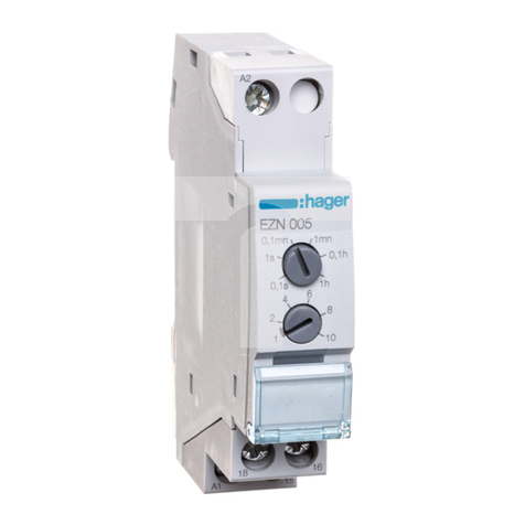
hager EZN005 User manual

hager

hager EZN005 User manual

hager RTQ520X User manual

hager

hager RTQ520X User manual

hager WUT09 User manual

hager

hager WUT09 User manual

hager coviva Smartbox TKP100A User manual

hager

hager coviva Smartbox TKP100A User manual

hager TX502 User manual

hager

hager TX502 User manual

hager 2-679-0630 User manual

hager

hager 2-679-0630 User manual

hager HZI855 User manual

hager

hager HZI855 User manual

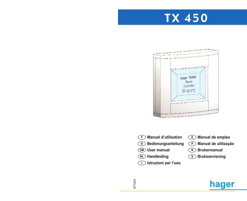
hager TX 450 User manual

hager

hager TX 450 User manual

hager coviva Smartbox TKP100A User manual

hager

hager coviva Smartbox TKP100A User manual

hager Kallysta WK304 User manual

hager

hager Kallysta WK304 User manual

hager TX502 User manual

hager

hager TX502 User manual

hager TX 223 User manual

hager

hager TX 223 User manual

hager EG 001 Installation instructions

hager

hager EG 001 Installation instructions

hager TX450B User manual

hager

hager TX450B User manual

hager WUT09 User manual

hager

hager WUT09 User manual

hager TX 206H User manual

hager

hager TX 206H User manual

Popular Controllers manuals by other brands

2M Technology 2MGST-6 user manual

2M Technology

2M Technology 2MGST-6 user manual

Ampcontrol imac itools user manual

Ampcontrol

Ampcontrol imac itools user manual

Kelly KLS8080N user manual

Kelly

Kelly KLS8080N user manual

BFT ICARO SMART AC A2000 Installation and user manual

BFT

BFT ICARO SMART AC A2000 Installation and user manual

ETC echoflex ELED2-BCL Configuration guide

ETC

ETC echoflex ELED2-BCL Configuration guide

Athena Controls RMB/12 Configuration and operation manual

Athena Controls

Athena Controls RMB/12 Configuration and operation manual

Parker Compax3 Fluid T40 installation manual

Parker

Parker Compax3 Fluid T40 installation manual

Siemens L-828 manual

Siemens

Siemens L-828 manual

Allen-Bradley PowerFlex 70 Reference manual

Allen-Bradley

Allen-Bradley PowerFlex 70 Reference manual

Mitsubishi Electric Q Series Programming manual

Mitsubishi Electric

Mitsubishi Electric Q Series Programming manual

Rutenbeck Control Plus IP4 installation instructions

Rutenbeck

Rutenbeck Control Plus IP4 installation instructions

Fiesta BLUE EMBER GRILLS iQue Instruction manual and use

Fiesta

Fiesta BLUE EMBER GRILLS iQue Instruction manual and use

YASKAWA AO-A3 User & installation manual

YASKAWA

YASKAWA AO-A3 User & installation manual

Omron NB-series Service guide

Omron

Omron NB-series Service guide

YOKOGAWA UT321 user manual

YOKOGAWA

YOKOGAWA UT321 user manual

Philips iPlayer 3 quick start guide

Philips

Philips iPlayer 3 quick start guide

ARRI UMC-4 user manual

ARRI

ARRI UMC-4 user manual

YASKAWA A1000 Series quick start guide

YASKAWA

YASKAWA A1000 Series quick start guide

manuals.online logo
manuals.online logoBrands
  • About & Mission
  • Contact us
  • Privacy Policy
  • Terms and Conditions

Copyright 2025 Manuals.Online. All Rights Reserved.