manuals.online logo
Brands
  1. Home
  2. •
  3. Brands
  4. •
  5. hager
  6. •
  7. Door Opening System
  8. •
  9. hager 4700 Series User manual

hager 4700 Series User manual

Page 1 of 3
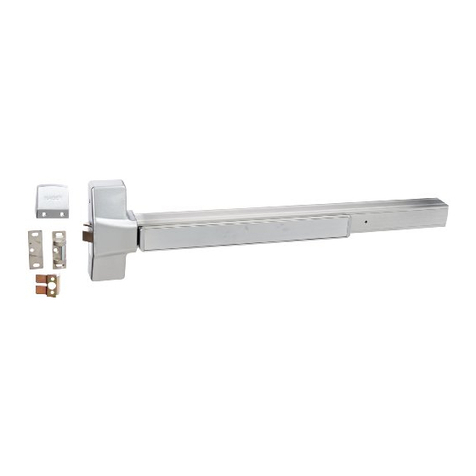
4700 Series Rim Exit Device
Installaon Instrucons
Grade 1
I-ED00790
Rev: 3 Rev Date: 7/16/2018
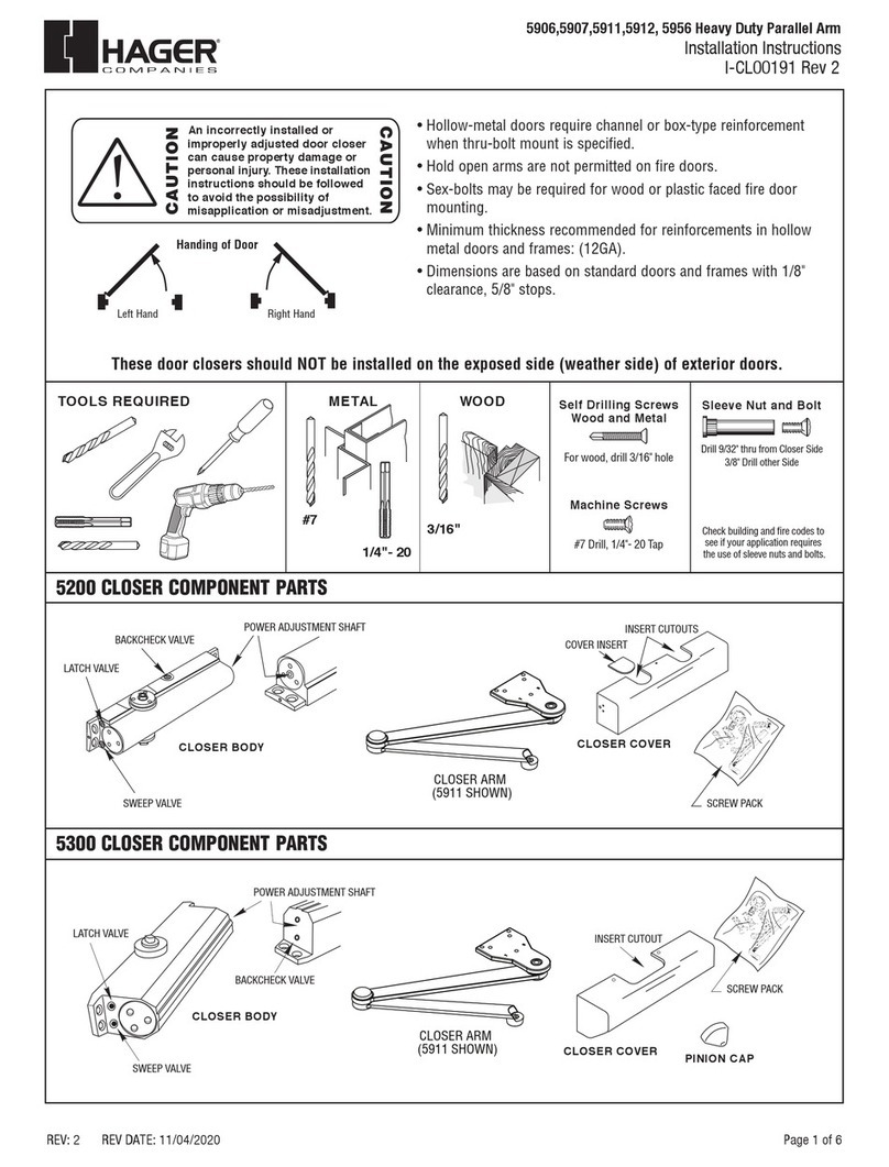
DEVICES COVERED IN THIS DOCUMENT:
4700R Rim Exit Device
4700RF Fire-Rated Rim Exit Device
Overview
SINGLE DOOR DOUBLE DOOR DOUBLE DOOR WITH MULLION
Tools Required METAL
WOOD SCREWS SEX BOLTS
For wood, drill 1/8” hole
Machine Screws
#7 Drill, 1/4”-20 Tap
Drill 5/16’ thru from
device side. Drill 3/8”
from other side (pull
side)
Check building and re
codes to see if your
applicaon requires
the use of sleeve nuts
and bolts.
COMPONENT PARTS
CHASSIS COVER
DOGGING WRENCH
DOGGING MECHANISM
(NOT AVAILABLE ON FIRE RATED DEVICES)
END CAP
END CAP BRACKET
LATCH CHASSIS
STRIKE (FIRE-RATED)
STRIKE (PANIC-RATED)
PUSH BAR
DEVICE BODY
Page 2 of 3
4700 Series Rim Exit Device
Installaon Instrucons
Grade 1
I-ED00790
Rev: 3 Rev Date: 7/16/2018
1. CUT EXIT DEVICE TO LENGTH 2. MARK DOOR AND DRILL MOUNTING HOLES
3. INSTALL DEVICE 4. INSTALL END CAP
RECOMMENDED OVERALL EXIT DEVICE LENGTH = DOOR WIDTH - 4”
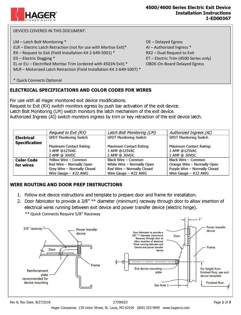
The exit device is pre-cut for 36” and 48” wide door use. For other door
widths, cut exit device to appropriate length. Recommended overall
length of the exit device is equal to door width minus four inches. Cut
with hacksaw or metal cung saw blade. Deburr edges.
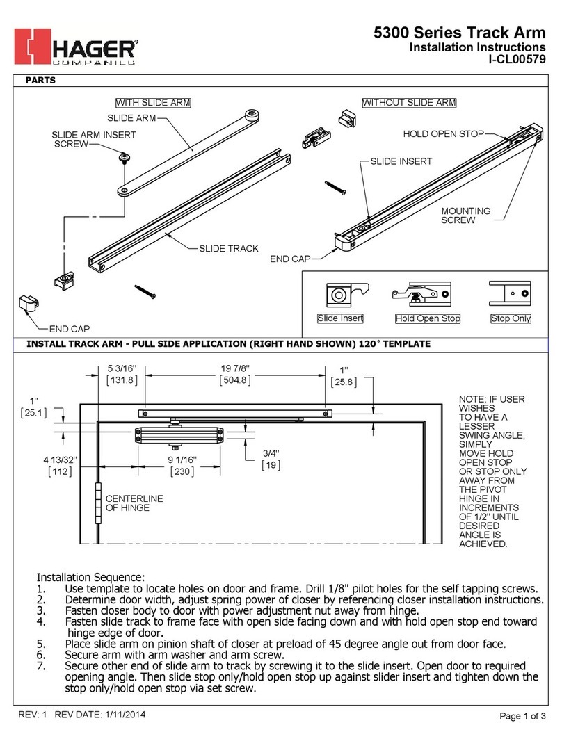
Measure center line of exit device, typically 40” from nished oor. Fold
and apply template to door and up against stop. Mark and drill holes as
shown on template. Be sure the vercal line of the exit device mounng
holes is 2-1/4” from the face of the stop. Do not drill center hole on strike
unl aer strike has been mounted and adjusted.
 For metal doors, drill and tap 1/4”-20 machine screws for both exit device and
strike.
 For wood doors, pre-drill 1/8” holes.
 If mounng trim, drill 5/16” clearance holes on exit device side (push side) of
door and 1/2” holes on pull side. Trim requires and addional 1/2” clearance
hole for the trim actuang sha (not required for dummy trim).
 If using sex bolts, drill 5/16” clearance holes on exit device side (push side) of
door and 3/8” on pull side.
Remove end cap from end cap bracket. Mark hole locaons by either using
template or holding end cap bracket up against door. Be sure exit device is
level before inserng end cap bracket lip into end of device body. Mark,
drill and tap holes. Install end cap bracket and end cap.
 For metal doors, drill and tap for 1/4”-20 machine screws.
 For wood doors, pre-drill 1/8” holes.
 For sex bolts, drill 5/16” clearance holes on exit device side (push side)
and 3/8” on pull side.
Screws
Metal door/sex bolt:
1/4”-20 machine screws (2)
Wood door:
#12 wood screws (2)
Remove head cover from exit
device chassis. Mount exit
device using the two
mounng holes indicated on
the template.
Screws
Metal door/sex bolt:
1/4”-20 machine screws (2)
Wood door: #12 wood screws (2)
If using trim, be sure to line up trim
actuang sha (tailpiece) with cam
located on back of exit device chassis.
Page 3 of 3
4700 Series Rim Exit Device
Installaon Instrucons
Grade 1
I-ED00790
Rev: 3 Rev Date: 7/16/2018
5. INSTALL STRIKE 6. INSTALL COVER
Install head cover on chassis using provided screws.
Install strike using only the top and boom sloed holes and 1/4” -20 machine screws
(metal) or pre-drill 1/8” hole for #12 wood screw. Open and close door to verify latch and
deadlatch are aligned properly. For ght t, move strike away from door. For loose t,
move strike towards door. Once strike is adjusted, install center screw. Fire-rated strike
does not use center screw.
Screws
Metal Stop:
1/4”-20 machine
screws (3)
Wood Stop:
#12 wood screws (3)
Fire-rated strike
7. DOG DEVICE
For increasing the life of this device, dog device down during high trac periods of the day. (A dogging device is not available on re rated models.)
Dogging:
Depress push bar, insert dogging hex wrench and turn clockwise 90 degrees. The push bar will remain depressed and the latch will stay retracted.
Release Dogging:
Hold push bar, insert dogging hex wrench and turn counterclockwise 90 degrees. The push bar will return to the up posion and latch will extend to
lock door

Other hager Door Opening System manuals

hager 4600 Series User manual

hager

hager 4600 Series User manual

hager 8300 Series User manual

hager

hager 8300 Series User manual

hager 4700S Service manual

hager

hager 4700S Service manual

hager 4500 Series User manual

hager

hager 4500 Series User manual

hager 4501 Service manual

hager

hager 4501 Service manual

hager 5906 User manual

hager

hager 5906 User manual

hager 5300 Series User manual

hager

hager 5300 Series User manual

hager 5200 Series User manual

hager

hager 5200 Series User manual

hager 4600 Series User manual

hager

hager 4600 Series User manual

hager 9850 Service manual

hager

hager 9850 Service manual

hager 5400 Series User manual

hager

hager 5400 Series User manual

hager 8300 Series Manual

hager

hager 8300 Series Manual

hager 5300 Series User manual

hager

hager 5300 Series User manual

Popular Door Opening System manuals by other brands

Dorma BEYOND Mounting instruction

Dorma

Dorma BEYOND Mounting instruction

Von Duprin 33/3527A installation instructions

Von Duprin

Von Duprin 33/3527A installation instructions

Record FlipFlow TWIN user manual

Record

Record FlipFlow TWIN user manual

Ingersoll-Rand VON DUPRIN 33 Series installation instructions

Ingersoll-Rand

Ingersoll-Rand VON DUPRIN 33 Series installation instructions

PortaPivot StealthPivot instruction manual

PortaPivot

PortaPivot StealthPivot instruction manual

DITEC PAS024AMT instructions

DITEC

DITEC PAS024AMT instructions

Beninca VN.45E Operating instructions and spare parts catalogue

Beninca

Beninca VN.45E Operating instructions and spare parts catalogue

Record BDE-D instruction manual

Record

Record BDE-D instruction manual

SUGATSUNE LAMP FD80-H installation manual

SUGATSUNE

SUGATSUNE LAMP FD80-H installation manual

Assa Abloy SARGENT FIREGUARD 12-2468 installation instructions

Assa Abloy

Assa Abloy SARGENT FIREGUARD 12-2468 installation instructions

KROME 950002 Installation instruction

KROME

KROME 950002 Installation instruction

GEM AD500 instruction manual

GEM

GEM AD500 instruction manual

NUKI Bridge installation guide

NUKI

NUKI Bridge installation guide

DITEC ENTREMATIC HA9 quick start guide

DITEC

DITEC ENTREMATIC HA9 quick start guide

DITEC 0DT848 Installation manual, maintenance, use

DITEC

DITEC 0DT848 Installation manual, maintenance, use

KALE KD-002/30-220 User & installation manual

KALE

KALE KD-002/30-220 User & installation manual

wink haus FM.A operating instructions

wink haus

wink haus FM.A operating instructions

Green Star Touch 'n Hold Smooth installation instructions

Green Star

Green Star Touch 'n Hold Smooth installation instructions

manuals.online logo
manuals.online logoBrands
  • About & Mission
  • Contact us
  • Privacy Policy
  • Terms and Conditions

Copyright 2025 Manuals.Online. All Rights Reserved.