2
Hager 03.2011
Hager AG - Ey 25 - 3063 Ittigen-Bern - Tel. 031 925 30 00 - Fax 031 925 30 05 www.hager-tehalit.ch
Hager AG - Glattalstrasse 521 - 8153 Rümlang - Tel. 044 817 71 71 - Fax 044 817 71 75 www.tebis.chHager
Hager SA - Chemin du Petit-Flon 31 - 1052 Le Mont-sur-Lausanne - Tél. 021 644 37 00 - Fax 021 644 37 05 infoch@hager.com
Installation (a)
Le thermostat d’ambiance doit être installé
à environ 1,5 m du sol, sur un mur intérieur,
à l’abri du rayonnement solaire direct et de
toute perturbation thermique telle que lampe
d’éclairage, téléviseur, tuyau de chauffage,
courant d’air (voir schéma d’installation “a”).
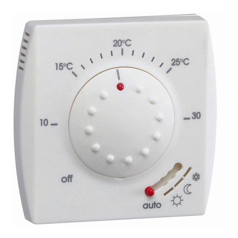
Description (b)
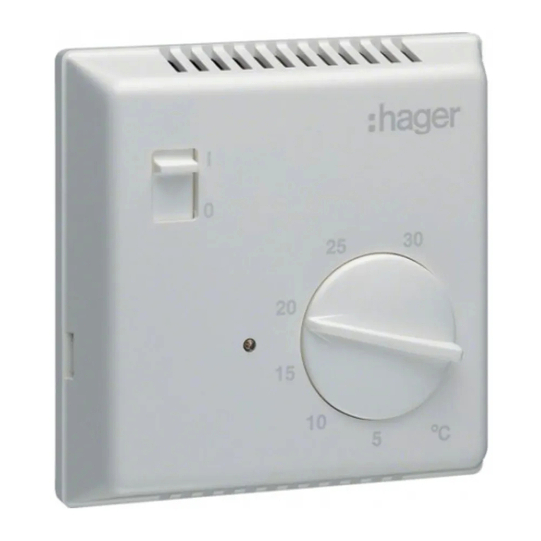
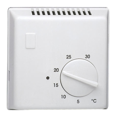
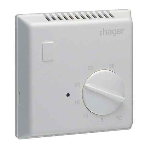
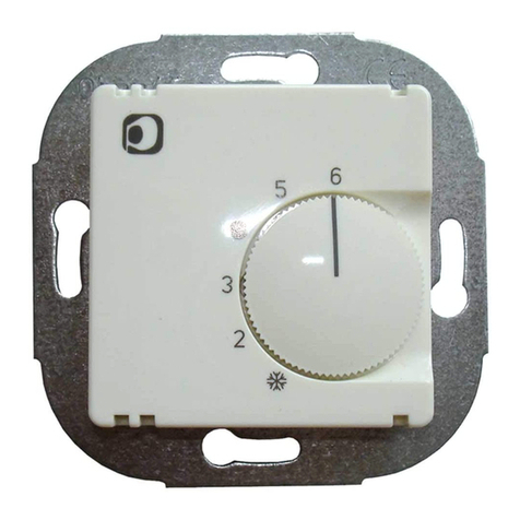
ABouton de réglage de température
BErgot de limitation d’échelle
CDisque (bleu et rouge)
DTempérature de confort
EHors-gel
FCommutateur Marche/arrêt
GLampe témoin de chauffe
Description des bornes
de connexion (c)
Entrées :
- L = Phase
- N = Neutre
- = Réduction de température
Sortie :
- = chauffage
Fonctionnement
En position “0” arrêt, le thermostat est
totalement inactif.
Lorsque la température ambiante est inférieure
à la température de consigne, le contact bimé-
tal ferme le circuit de chauffe jusqu’à atteinte
de la température désirée.
Contact horaire :
-
Ouvert : la température est régulée normalement
- Fermé : la température est régulée et réduite
d’environ 4K.
Limitation de la plage
de température (b)
La plage de température peut être réduite
de la façon suivante :
1-
Enlever le bouton de réglage de température A
2- Soulever l’ergot de limitation B
3- Ajuster le disque rouge Cafin de définir
la température maximale désirée
4- Ajuster le disque bleu Cafin de définir
la température minimale désirée
5- Replacer l’ergot B
6- Replacer le bouton A
Recommandations
- Toujours placer le thermostat dans la partie la
plus basse, dans le cas de plaque multiposte.
- N’utiliser que les pièces d’origine.
Caractéristiques techniques
- Capteur : bimétal, type 1C
- Tension d’alimentation: 230 V, 50 Hz
- Plage de réglage : +5°C à +30°C
- Relais de sortie : 10 (4)A
- Hystérésis : environ 0,5°C
- Classe II après installation complète
- Indice de protection : IP 30
- Capacité de raccordement : 0,5 à 2,5 mm2
- Humidité d’air maximale : 95%
Installation (a)
Der Temperaturregler solle in einem Abstand
von ungefähr 1,5 m vom Boden und an einer
Innenwand liegend installiert werden.
Geschützt vor direkter Sonneneinstrahlung und
jeglicher thermischen Störung, wie z.B.
Leuchte, Fernseher, Heizungsrohr, Luftzug,
installieren - siehe Installationsplan (a).
Beschreibung (b)
ATemperaturregelungsknopf
BBegrenzung des Einstellbereiches
CScheiben (blau und rot)
DKomfort-Temperatur
EFrostschutz
FEin-/Aus-Schalter
GHeizstatusanzeige
Beschreibung der
Anschlussklemmen (c)
Eingänge :
- L = Phase
- N = Neutralleiter
- = Temperaturabsenkung
Ausgang :
- = Heizlast
Funktion
In der Aus-Stellung ist die Regelung des
Thermostat vollständig deaktiviert.
Wenn die Raumtemperatur unterhalb der
eingestellten Temperatur sinkt, schließt der
Bimetallkontakt den Heizkreis, bis die
gewünschte Temperatur erreicht wird.
Uhrkontakt :
- Offen : die Temperatur wird normal geregelt
- Geschlossen : die Temperatur wird um ca. 4K
abgesenkt.
Begrenzung des
Temperaturbereiches (b)
Der Temperaturbereich kann wie folgt
eingestellt werden :
1- Temperaturregelungsknopf Aentfernen
2- Stift Banheben
3- Zur Festlegung der maximal gewünschten
Temperatur, rote Scheibe Ceinstellen
4- Zur Festlegung der minimal gewünschten
Temperatur, blaue Scheibe Ceinstellen
5- Stift Beinstecken
6- Knopf Aaufsetzen
Empfehlungen
- Bei Mehrfachrahmen, den Regler an der
untersten Stelle positionieren.
- Ausschließlich Original-Ersatzteile verwenden.
Technische Daten
- Meßfühler : Bimetall, Typ 1C
- Betriebsspannung : 230 V, 50 Hz
- Einstellbereich : +5°C bis +30°C
- Schaltleistung : 10 (4)A
- Hysteresis : etwa 0,5°C
- Schutzklasse II, nach vollständiger Montage
- Schutzart : IP 30
- Anschlusskapazität : 0,5 ... 2,5 mm2
- Max. Luftfeuchtigkeit : 95%
Installation (a)
The controller has to be installed ideally at about
1,5 m from the floor, on an inside wall, sheltered
from direct sun radiation and from all thermal
disturbance, such as lighting lamp, television,
heating pipe, draught - see installation layout (a).
Description (b)
ATemperature adjustment button
BScale limitation lug
CWheels (blue and red)
DComfort temperature
EAntifreeze function
FOn/Off switch
GHeating indicating lamp
Description of the terminals (c)
Inputs :
- L = Phase
- N = Neutral
- = temperature decrease
Output :
- = heating
Working
In Off position, regulation is totally inactive.
If the room temperature falls below the temperature
set, the bimetal contact closes the heating circuit
until the desired temperature is reached.
Clock contact :
- Open : the temperature is adjusted normally
- Closed : the temperature is adjusted and reduced
by about 4K.
Limitation of the temperature range (b)
The temperature range can be reduced as follows :
1- Remove the temperature adjustment button A
2- Lift the limitation lug B
3- Adjust the red wheel Cto define the max.
desired temperature
4- Adjust the blue wheel Cto define the min.
desired temperature
5- Put back the lug B
6- Put back the button A
Recommendations
- In case of multi-position plates, put always
the thermostat at bottom position.
- Use only genuine parts.
Technical data
- Sensor : bimetal, type 1C
- Supply voltage : 230 V, 50 Hz
- Adjustment range : +5°C to +30°C
- Output relay: 10 (4)A
- Hysteresis : about 0,5°C
- Class II, after complete installation
- Degree of protection : IP 30
- Connection capacity : 0,5 ... 2,5 mm2
- Air moisture maxi : 95%
Attention :
- Appareil à installer uniquement
par un installateur électricien.
- Ne pas utiliser le produit sans
ses protections externes.
Achtung :
- Einbau und Montage dürfen nur durch
eine Elektrofachkraft erfolgen.
- Dieses Gerät darf nicht ohne seine
Design-Abdeckungen benutzt werden.
Caution :
- This device must be installed only
by a qualified electrical fitter.
- Do not use without its external protections.
°£°¢°§
