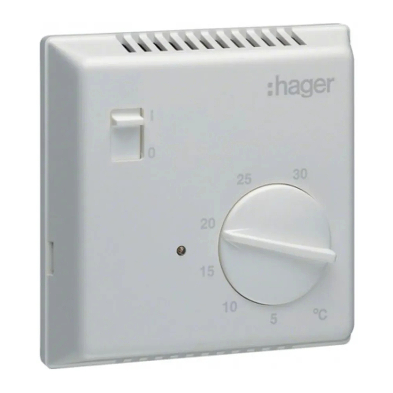
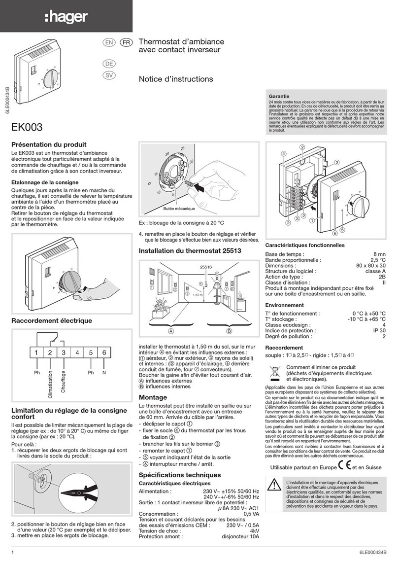
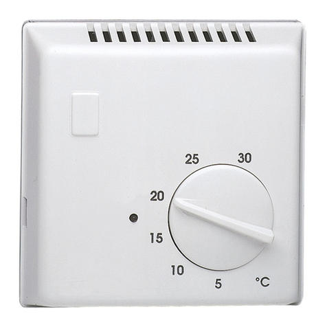
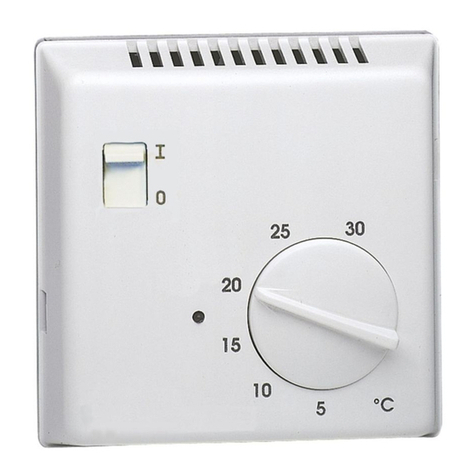
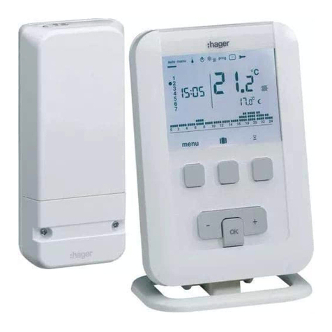
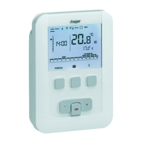
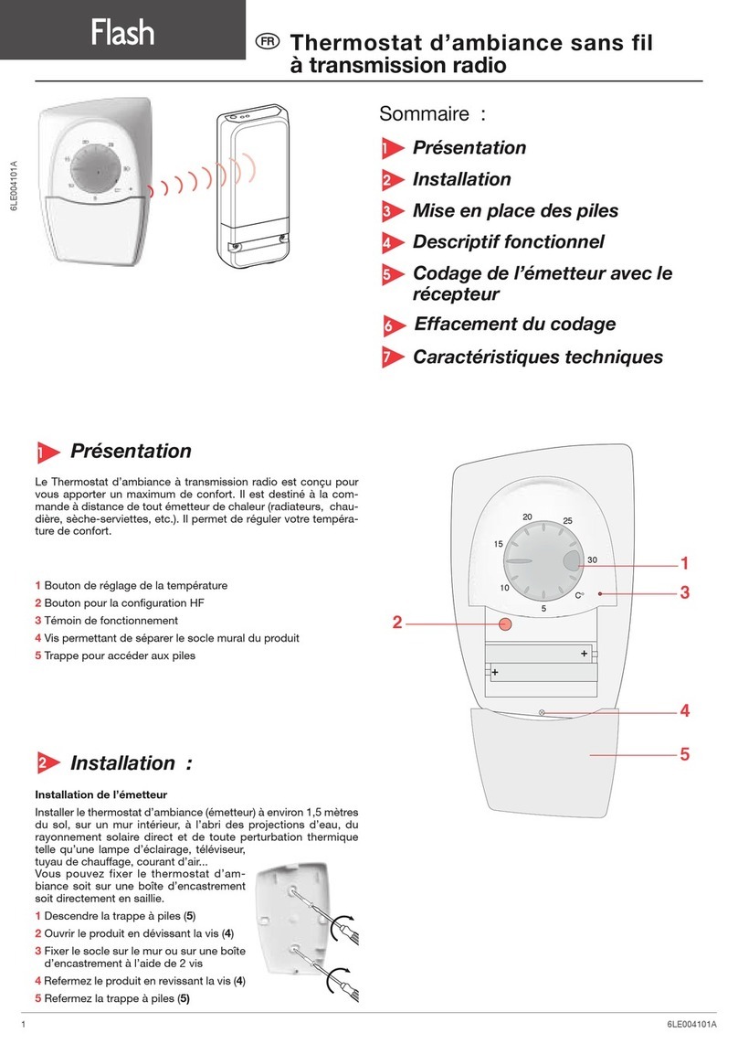
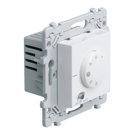
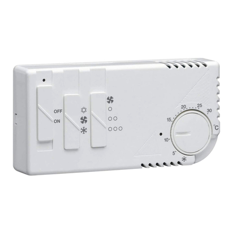
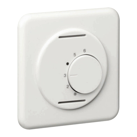
hager WE310 User manual

6LE007200B
6LE007200B
1
WE310, WE310T
essensya
(a)
(
12
3
4
5
76
BA
WXF310
1,50 m
AI1_WS310_T1_02
WE310
WE310
1,50 m
b) - (e)
(c)
N
L
12NL
NO
L
WE310
(d)
a
e
z
a
Thermostat d’ambiance électronique
Consignes de sécurité
L’installation et le montage d’appareils électriques
doivent être eectués uniquement par des
électriciens qualifiés, en conformité avec les normes
d’installation et dans le respect des directives,
dispositions et consignes de sécurité et de
prévention des accidents en vigueur dans le pays.
Le non-respect des consignes d'installation
peut entraîner des dommages sur l'appareils,
un incendie ou présenter d'autres dangers.
Ce mode d'emploi fait partie intégrante du produit
et doit être conservée par l'utilisateur final.
Installation (a)
Le thermostat d’ambiance doit être installé à
environ 1,5 m du sol, sur un mur intérieur, à l’abri du
rayonnement solaire direct et de toute perturbation
thermique telle que lampe d’éclairage, téléviseur,
tuyau de chauage, courant d’air (voir schéma
d’installation “a”).
Cas d’usage typique :
- Convient uniquement pour une utilisation à
l'intérieur et à l'abri de toute humidité.
Description (b)
ABouton de réglage de température
BErgot de limitation d’échelle
CDisque (bleu et rouge)
DCommutateur OFF / (réduit) /
E Pointeur de température
Le commutateur devient lumineux lorsque le
chauage / la climatisation est en fonction.
Raccordement électrique (c)
Connecter le chauage ou la climatisation à
la borne 2 “NO”. La logique de commande est
automatiquement inversée en mode climatisation !
Modification du mode de fonctionnement,
climatisation ou chauage (d)
Le thermostat est livré en mode “chauage”.
Pour passer en mode “climatisation” suivre la
séquence décrite en (d):
0 Pour débuter, placer le commutateur sur OFF
et la température en “butée minimale”.
1Placer le commutateur sur .
2Régler la température en “butée maximale”.
3Placer le commutateur sur OFF.
4la température en “butée minimale”.
5Placer le commutateur sur .
A la fin de la séquence, le commutateur clignote
3 fois pour signaler le changement de mode.
Si plus de 15 secondes s’écoulent entre les
diérentes étapes il faut recommencer la séquence
à l’étape 0.
Vérification du mode de fonctionnement
Mode chauage : si température ambiante inférieure
à température de consigne alors le voyant du
commutateur est allumé (inversement en mode
climatisation).
Limitation de la plage de température (e)
La plage de température peut être réduite de la
façon suivante :
1- Enlever le bouton de réglage de température A
2- Soulever l’ergot de limitation B
3- Ajuster le disque rouge Cafin de définir
la température maximale désirée
4- Ajuster le disque bleu Cafin de définir
la température minimale désirée
5- Replacer l’ergot B
6- Replacer le bouton A
Caractéristiques techniques
- Tension d’alimentation :
230Vv+10 % / -15% 50 Hz
- Plage de réglage: +5 °C à +30 °C
- Température d’utilisation: 0 °C à 50 °C
- Température de stockage: -20 °C à +60 °C
- Relais de sortie: 8A AC1
- Précision de température: ± 0,7 °C @ 8A
- Classe: II
Utilisable partout en Europe M
Comment éliminer ce produit
(déchets d’équipements
électriques et électroniques).
a
(Applicable dans les pays de l’Union Européenne et
aux autres pays européens disposant de systèmes de
collecte sélective).
Ce symbole sur le produit ou sa documentation indique
qu’il ne doit pas être éliminé en fin de vie avec les autres
déchets ménagers. L’élimination incontrôlée des déchets
pouvant porter préjudice à l’environnement ou à la santé
humaine, veuillez le séparer des autres types de déchets
et le recycler de façon responsable. Vous favoriserez ainsi
la réutilisation durable des ressources matérielles.
Les particuliers sont invités à contacter le distributeur
leur ayant vendu le produit ou à se renseigner auprès
de leur mairie pour savoir où et comment ils peuvent se
débarrasser de ce produit afin qu’il soit recyclé en
respectant l’environnement.
Les entreprises sont invitées à contacter leurs fournisseurs
et à consulter les conditions de leur contrat de vente. Ce
produit ne doit pas être éliminé avec les autres déchets
commerciaux.
e
Elektronischer Raumthermostat
Sicherheitshinweise
Einbau und Montage elektrischer Geräte
dürfen nur durch eine Elektrofachkraft gemäß
den einschlägigen Installationsnormen,
Richtlinien, Bestimmungen, Sicherheits- und
Unfallverhütungsvorschriften des Landes erfolgen.
Bei Nichtbeachten der Installationshinweise
können Schäden an den Geräten,
Brand oder andere Gefahren entstehen.
Diese Anleitung ist Bestandteil des Produktes und
muss beim Endanwender verbleiben.
Installation (a)
Er solle in einem Abstand von ungefähr 1,5 m vom
Boden und an einer Innenwand liegend installiert
werden. Geschützt von direkter Sonneneinstrahlung
und jeglicher thermischen Störung, wie z.B.
Leuchte, Fernseher, Heizungsrohr, Luftzug,
anbringen (siehe Installationsplan “a”).
Bestimmungsgemäßer Gebrauch :
- Ausschließlich zum Gebrauch in tropf- und
spritzwasserfreien Innenbereichen geeignet.
Beschreibung (b)
ATemperaturregelungsknopf
BBegrenzung des Einstellbereiches
CScheibe (blau und rot)
DUmschalter OFF / (Absenkung) /
ETemperatureinstellungsmarkierung
Der Umschalter leuchtet, wenn die Heizung/
Klimaanlage aktiviert ist.
Elektrischer Anschluss (c)
Heizung bzw. Klimaanlage an der Klemme 2 “NO”
anschließen. Im Modus Klimaanlage wird die
Steuerungslogik automatisch umgekehr!
Betriebsart “Heizung/Klimaanlage” ändern (d)
Das Thermostat wird mit der Werkseinstellung
“Heizung” ausgeliefert. Zum Umschalten in den
“Klima-Modus” ist die unter (d) beschriebene
Sequenz zu beachten:
0Erster Schritt: Schalter auf OFF stellen
und Temperatur auf “Min.” (Anschlag) stellen.
- Indice de protection: IP 20
- Capacité de raccordement : 1 x 1,5 mm2
1 x 2,5 mm2
- Mode de fonctionnement mémorisé indéfiniment
- : Réduit = -3 °C chauage / +3 °C climatisation
Recommendations
• Appareil à installer uniquement par un
professionnel habilité.
• N’utiliser que les pièces d’origine.
• Ne pas utiliser le produit sans les protections
externes.

1Schalter auf stellen.
2Temperatur auf “Max.” (Anschlag) stellen.
3Schalter auf OFF stellen.
4Temperatur auf “Min.” (Anschlag) stellen.
5Schalter auf stellen.
Nach Abschluß dieser Sequenz signalisiert der
Schalter durch dreimaliges Blinken, daß der
Betriebsartwechsel vollzogen ist. Sollten zwischen
den unterschiedlichen Schritten der Sequenz über
15 Sekunden verstreichen, ist die Sequenz ab
Schritt 0neu zu beginnen.
Betriebsart überprüfen
Heizmodus : Unterschreitet die Raumtemperatur
den Sollwert, leuchtet die Kontrollleuchte am
Schalter auf (im Klima-Modus geschieht dasselbe
umgekehrt).
Begrenzung des Temperaturbereiches (e)
Der Temperaturbereich kann wie folgt eingestellt
werden :
1- Temperaturregelungsknopf Aentfernen
2- Stift Banheben
3- Zur Festlegung der maximal gewünschten
Temperatur, rote Scheibe Ceinstellen
4- Zur Festlegung der minimal gewünschten
Temperatur, blaue Scheibe C einstellen
5- Stift Bwiedereinsetzen
6- Knopf A wiedereinsetzen
Elektrische Daten
- Betriebspannung : 230Vv+10 % / -15% 50 Hz
- Einstellbereich: +5 °C bis +30 °C
- Arbeitstemperatur : 0 °C bis 50 °C
- Lagerungstemperatur : -20 °C bis +60 °C
- Schaltleistung : 8A AC1
- Temperaturgenauigkeit: ± 0,7 °C @ 8A
- Schutzklasse : II
- Schutzart : IP 20
- Anschlusskapazität : 1 x 1,5 mm2
1 x 2,5 mm2
- Die eingestellte Betriebsart bleibt zeitlich
unbegrenzt gespeichert
- : Absenkung = -3 °C Heizung / +3 °C Klimaanlage
Empfehlungen
• Einbau und Montage dürfen nur durch eine
Elektrofachkraft erfolgen.
• Ausschließlich Original-Ersatzteile verwenden.
• Gerät keinesfalls ohne die äußere
Schutzverkleidungen einsetzen.
z
Electronic room thermostat
Safety instructions
Electrical equipment may only be installed
and assembled by a qualified electrician in
accordance with the relevant installation standards,
guidelines, regulations, directives, safety and
accident prevention regulations of the country.
Failure to comply with these installation
instructions may result in damage
to the devices, fire or other hazards.
These instructions are an integral component of the
product and must be retained by the end user.
Installation (a)
It has to be installed ideally at about 1,5 m from the
floor, on an inside wall, sheltered from direct sun
radiation and from all thermal disturbance, such as
lighting lamp, television, heating pipe, draught (see
installation layout “a”).
Correct use:
- Only suitable for use in indoor areas with no drip
and no spray water.
Description (b)
ATemperature adjustment button
BScale limitation lug
CWheel (blue and red)
DChange-over switch OFF / (reduced) /
ETemperature pointer
The switch lights up when the heating / air
conditioning system is in operation.
Electrical connection (c)
Connect heating or air-conditioning system to the
terminal 2 "NO". The control logic is automatically
reversed in air-conditioning mode !
Changing operation mode, air-conditioning or
heating (d)
The product is delivered with thermostat set
to “heating” mode. Follow instructions below to
switch to “air-conditioning” mode (d) :
0For starting, switch OFF and set the temperature
to “minimum stop” position
1Switch .
2Set the temperature to “maximum stop”.
3Switch OFF.
4Set the temperature to “minimum stop”.
5Switch .
At the end of the sequence, the switch blinks
3 times to signal the change of mode. If the time
between the various steps exceeds 15 sec, the
sequence shall be run again starting from 0step.
Checking the operation mode
Heating mode : if the room temperature is below
the temperature set, the switch indicator shall be
on (and conversely in air-conditioning mode).
Limitation of the temperature range (e)
The temperature range can be reduced as follows :
1- Remove the temperature adjustment
button A
2- Lift the limitation lug B
3- Adjust the red wheel Cto define the maxi
desired temperature
4- Adjust the blue wheel Cto define the mini
desired temperature
5- Put back the lug B
6- Put back the button A
Electrical data
- Supply voltage : 230Vv+10 % / -15% 50 Hz
- Adjustment range: +5 °C up to +30 °C
- Operating temperature : 0 °C up to 50 °C
- Storage temperature: -20 °C up to +60 °C
- Output relay: 8A AC1
- Temperature accuracy: ± 0,7 °C @ 8 A
- Class: II
- Degree of protection: IP 20
- Connection capacity : 1 x 1,5 mm2
1 x 2,5 mm2
- The operating mode is stored indefinitely
- : Reduced = -3°C Heating+3 °Cair-conditioning
Usable in all Europe M
Correct Disposal of this
product
(Waste Electrical & Electronic
Equipment)
z
(Applicable in the European Union and other European
countries with separate collection systems).
This marking shown on the product or its literature
indicates that it should not be disposed with other
household waste at the end of its working life. To prevent
possible harm to the environment or human health from
uncontrolled waste disposal, please separate this from
other types of wastes and recycle it responsibly to
promote the sustainable reuse of material resources.
Household users should contact either the retailer where
they purchased this product, or their local government
oce, for details of where and how they can take this
device for environmentally safe recycling.
Business users should contact their supplier and check
the terms and conditions of the purchase contract. This
product should not be mixed with other commercial
wastes of disposal.
Verwendbar in ganz Europa M
Korrekte Entsorgung dieses
Produkts (Elektromüll). a
(Anzuwenden in den Ländern der Europäischen
Union und anderen europäischen Ländern mit
einem separaten Sammelsystem).
Die Kennzeichnung auf dem Produkt bzw. auf der
dazugehörigen Literatur gibt an, dass es nach seiner
Lebensdauer nicht zusammen mit dem normalen
Hausmüll entsorgt werden darf.
Entsorgen Sie dieses Gerät bitte getrennt von anderen
Abfällen, um der Umwelt bzw. Der menschlichen
Gesundheit nicht durch unkontrollierte Müllbeseitigung
zu schaden.
Recyceln Sie das Gerät, um die nachhaltige
Wiederverwertung von stoichen Ressourcen zu fördern.
Private Nutzer sollten den Händler, bei dem das
Produkt gekaut wurde, oder die zuständigen Behörden
kontaktieren, um in Erfahrung zu bringen, wie sie das
Gerät auf umweltfreundlicheWeise recyceln können.
Gewerbliche Nutzer sollten sich an ihren Lieferanten
wenden und die Bedingungen des Verkaufsvertrags
konsultieren.
Dieses Produkt darf nicht zusammen mit anderem
Gewerbemüll entsorgt werden.
Hager Electro S.A.S., Boulevard d'Europe, B.P. 3, 67215 OBERNAI CEDEX, France - www.hager.com Hager 09.20 6LE007200B2
Recommendations
• This device shall be installed solely by a
professional installer.
• Use only genuine parts.
• Never use the product with external protection
devices removed.
This manual suits for next models
1
Other hager Thermostat manuals

hager
hager 54185 User manual

hager
hager 58102 User manual

hager
hager EK760 User manual

hager
hager 25501 User manual

hager
hager Flash 25620 User manual

hager
hager EK 053 User manual

hager
hager EK052 Installation instructions

hager
hager kallysta WK310 User manual

hager
hager EK004 User manual

hager
hager 25311 User manual

hager
hager EK530 User manual

hager
hager WS310 systo User manual

hager
hager 25614 Installation instructions

hager
hager 58102 User manual

hager
hager EK053 User manual

hager
hager kallysto WUC70 User manual

hager
hager EK510 User manual

hager
hager Bocchiotti 25310 User manual

hager
hager WH104405 Series User manual

hager
hager EK051 User manual