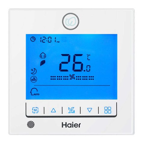
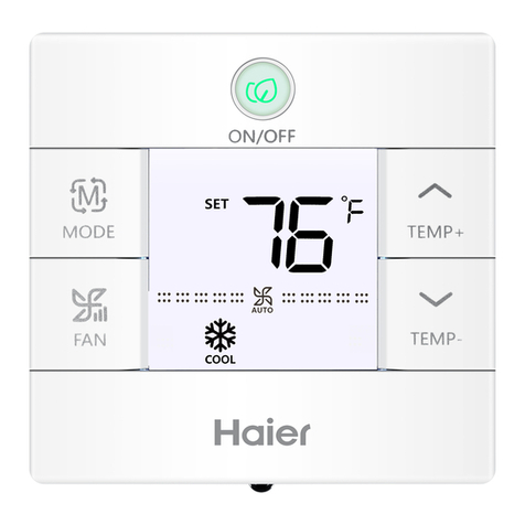
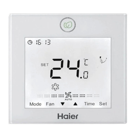
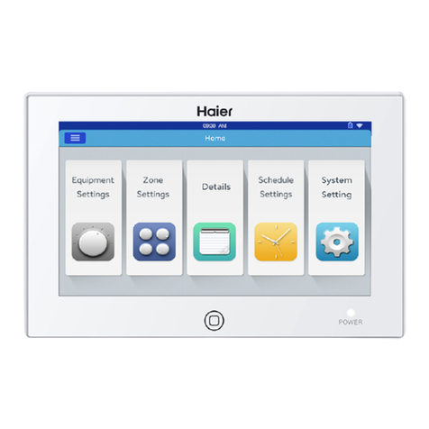
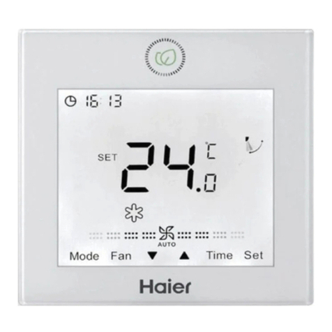
Haier QACT17A User manual

TableofContents
PartsandFunctions
InterfaceDisplay .........................................................................1
Icons..............................................................................................2
DipSwitch ...................................................................................4
Operation
ModeKey ....................................................................................6
FanKey ........................................................................................6
TemperatureAdjustmentKeys .................................................7
SpecialFunction
SpecialFunctionSelection..........................................................8
InstallerSettings
AdjustECOParameters ...........................................................10
ChildLock ................................................................................10
LockSettings ............................................................................11
Fahrenheit/Celsius ..................................................................11
TemperatureCompensation ...................................................12
ForcedDefrost/Cooling/Heating ............................................12
ErrorChecks .............................................................................13
ModeRestriction ......................................................................14
ModeCombinationSettings ....................................................15
WiringInstruction ....................................................................15
WiredController
InstallationandOperationManual
QACT17A
¬Ùïèäöèõèäç÷ëìöðäñøäïåèéòõèøöè
¬Ùïèäöèîèèó÷ëìöðäñøäïéòõéø÷øõèõèéèõèñæè 49-5000061 Rev.6
GEA 08-21

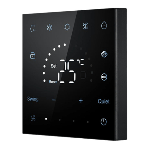
SUB
MAIN
Full Display
1
PartsandFunctions
InterfaceDisplay

/
2
Roomtemperaturedisplay(dipswitchSW1-2
on).
Settemperaturedisplay
Filter
HRV(HeatReclaimVentilation),ifHRV
functionisset,itwilldisplaythisicon
Erroricondisplaysdetectedfault
ECOmodeon
Central/lockwhenconnectedtoacentral
controller
UP/DOWNlouverswing
LEFT/RIGHTlouverswing
Childlockon
PartsandFunctions
Icons

MAIN/SUB Main/Subordinatewired
controller
QuietFanSpeed
(somemodels)
LowFanSpeed
MediumFanSpeed
HighFanSpeed
TurboFanSpeed
(somemodels)
AutoFanspeedisindicatedbythedisplayautomatically
steppingfromlowtohighrepeatedly.
AutoMode
CoolingMode
HeatingMode
FanMode
3
PartsAndFunctions

4
Íìóöúì÷æëçèĤñì÷ìòñ
DipSwitch SW1
DipSwitch
SW1 ON OFF Default
Sw1-1 Subordinatewired
controller Mainwiredcontroller OFF
Sw1-2 Roomtemperature
displayon Roomtemperature
çìöóïäüòģ OFF
Sw1-3
Roomtemperature
collectedfromindoorunit
Roomtemperature
collectedfromcontroller OFF
Sw1-4 Üüö÷èðõèðäìñöòģäé÷èõ
powerloss Autorestartafterpower
loss OFF
Sw1-5 Oldprotocol(models
developedbeforeAug.
2013) Newprotocol OFF
Sw1-6 Backlightalwayson
Backlight15secondauto
timeout
OFF
Sw1-7 Reserved Reserved OFF
Sw1-8 Reserved Reserved OFF

5
DipSwitch SW2
Initialization
àëèñ÷ëèðìñì¡öóïì÷öüö÷èðìöóòúèõèçòñ(((úìïïĥäöëåè÷úèèñ
theRoomTemperaturedisplayandtheSetTemperaturedisplay
untilcommunicationisestablishedwiththeindoorunit.
Press topowerONorpowerOFFthecontrol.Atonewillbe
heardwitheverybuttonpressorwhenacommandisreceivedby
äõèðò÷èæòñ÷õòïÒéäæòñĥìæ÷ìñêæòððäñçìöõèæèìùèç÷ëèñ÷ëè
tonewillsound3times.
AudibleAlert
DipSwitch
SW2 ON OFF Default
Sw2-1 ModeLock Normal OFF
Sw2-2 ×òåø÷÷òñæòñĤõðä÷ìòñ÷òñè¤Ýòñèúìïï
stillsoundwhencommandissentby
wirelessremote. Toneon OFF
Sw2-3 Reserved Reserved OFF
Sw2-4 Reserved Reserved OFF

QuietFanSpeed
(somemodels)
LowFanSpeed
MediumFanSpeed
HighFanSpeed
TurboFanSpeed
(somemodels)
6
Modekey:
•
EachpressoftheMODEbuttonwillchangetheoperating mode
éõòðÊø÷ò¢Ìòòï¢Ñèä÷¢Ïäñ¢Íõü¤ÍèëøðìçìĤæä÷ìòñ¥¢Êø÷ò
•Eachmodehasitsinitialdefaultfanspeed.
ModeKey/FanKey
Mode Fanspeed Temperature
Auto Auto 76°F
Cool High 76°F
Heat Auto 76°F
Fan Low Notemperaturedisplay
Íõü¤ÍèëøðìçìĤæä÷ìòñ¥ Auto 76°F
Initial
State
FanKey:
EachpressoftheFANbuttonwillchangethefanspeedfrom
Auto–Quiet(somemodels)–Low–Medium–High–Turbo
¤öòðèðòçèïö¥¢Êø÷ò

7
TemperatureAdjustmentKeys: /
• PresstheTEMP+orTEMP-keystochangethetemperatureby
1°Fincrements.
•ThetemperaturesetpointrangeforAuto,Cooling,Heating
äñçÍõü¤ÍèëøðìçìĤæä÷ìòñ¥ìö& Ï(&ϤÒéÎÌØìöòñ
thentemperaturerangewillchangepertheECOsetting
parameters).
•ThetemperatureissetindependentlyunderAuto,Cooling,
HeatingandDehumidifymodes.Oncethetemperatureisset
ineachmodethesettingwillbesavedforthatmode.
•Infanmode,Temp+/-keysdonotwork.
Temperature

8
SpecialFunctionSelection:
Withthecontrolpoweredon,pressandholdtheTEMP+for
5secondstoenterthespecialfunctionmenu.Allthespecial
functioniconswilldisplay.UsetheTEMP+andTEMP-buttonsto
movebetweenicons.UseFANbuttontoselectfunction.
FunctionSelection

9
FunctionSelection
50

10
AdjustECOParameters:
• Cooling:Powerontheunit.Adjustsettemperatureto86°F.
PressandholdFANandTEMP+for5seconds.Theminimum
allowablesettemperaturewillbedisplayedinthetopright
corner.UseTEMP+/-tochangetheparameter,thenpressFAN
save.Thedefaultminimumtemperatureis73°F.
• Heating:Powerontheunit.Adjustsettemperature60°F.
PressandholdFANandTEMP-for5seconds.Themaximum
allowablesettemperaturewillbedisplayedinthetopright
corner.PressTEMP+/-tochangetheparameter,thenpress
FANtosave.Thedefaultmaximumtemperatureis79°F.
¬Íõü¤ÍèëøðìçìĤæä÷ìòñ¥ÎÌØóäõäðè÷èõöäõè÷ëèöäðèäöÌòòïìñê
ChildLock:
• PressandholdTEMP+andTEMP-for5secondstoactivate/
deactivatetheChildLockfunction.WhentheChildLock
functionisactive, willappear.
InstallerSettings

11
Central/LockFunction: /
Functionisactiveonlywhensystemhasacentralcontrol,suchas
theYCZ-A004.ThissettingisactivatedonlybythecentralControl.
FahrenheitSettingandDisplay:
• FahrenheittoCelsius:Adjustsettemperaturetolowest
öè÷÷ìñê& ÏúëèñÎÌØìöòģÙõèööäñçëòïçÝÎÖÙ¡éòõ!%
seconds.Duringthe15secondcountthedisplaywillbeep
onceat5secondsanddisplayerrorcodes.Thenafteranother
5seconds,thedisplaywillbeeponceagainanddisplay00,
after5moresecondsthedisplaywillchangetoCelsius.
• CelsiustoFahrenheit:Adjustsettemperaturetohighest
öè÷÷ìñê# ÌúëèñÎæòìöòģÙõèööäñçëòïçÝÎÖÙéòõ!%
seconds.Duringthe15secondcount,thedisplaywillbeep
onceat5secondsandenterSpecialFunctionsmenu.Then
afteranother5seconds,thedisplaywillshow00,after5more
secondsthedisplaywillchangetoFahrenheit.
LockSettings/FahrenheitSetting
CentralControl Øñ¦Øģéøñæ÷ìòñòñïüäùäìïäåïè
CentralLock Nofunctionsavailable.

12
SetTemperatureCompensation:
¬àì÷ë÷ëèçìöóïäüòģóõèööäñçëòïç÷ëèÏÊ×åø÷÷òñéòõ%öèæòñçöÝëè
displaywillthenshow0(default)orcurrentcompensationsetting.Use
TEMP+/-buttonstoadjustthecompensation.Compensationcanbe
setin1°increments
+/-8°F(0.5°Cincrementsupto+/-4°C).
• Temperaturecompensationchangestheambienttemperature
reading.Ifthesystemissensingtheambienttemperatureat72°F
andthecompensationissetto-2°thenthesystemwilluse70°Finits
operationtoheatorcool.
ForcedDefrost:
• SettoHeatingmode,highfan,and86°F(30°C),orhighesttemperature
ifECOis on.PressTEMP+6timeswithin5seconds.Threetoneswill
æòñĤõð÷ëä÷÷ëèøñì÷ìöìñéòõæèççèéõòö÷ðòçè
ForcedCooling:
• SetmodetoCool.TapON/OFF.Tapanybutton,exceptON/OFF,to
lightthedisplay.PressandholdON/OFFfor5seconds.LLwilldisplay
äñç÷ëèæòñ÷õòïúìïïåèèó÷úìæèÝòèûì÷÷øõñòģæòñ÷õòïäñç÷øõñì÷òñ
again.
ForcedHeating:
• SetmodetoHeat.TapON/OFF.Tapanybutton,exceptON/OFF,to
lightthedisplay. PressandholdON/OFFfor5seconds.HHwilldisplay
äñç÷ëèæòñ÷õòïúìïïåèèó÷úìæèÝòèûì÷÷øõñòģæòñ÷õòïäñç÷øõñì÷òñ
again.
TemperatureCompensation

13
Howtocheckerror:
¬Òé÷ëèõèìöäñèõõòõ willdisplay.
¬ÌëèæîèõõòõÙõèööäñçëòïçÝÎÖÙ¡åø÷÷òñéòõ%öèæòñçöÝëè
errorhistorywillappearinthetoprightcorner.Thecurrent
errorwillappearinthemiddleofthescreen.Ifthereisnoerror,
“--”willdisplay.
ErrorChecks

14
ModeRestrictionFunction:
•WhenSW2-1ison,thesystemmodelockison.Thiswilllock
themodetoHeat,Cool,DryorFan.Nobuttonpresscan
changemode.Allothercontrolfunctionsareavailablesuchas
éäñöóèèçöè÷÷èðóèõä÷øõèäñçòñ¦òģ
•Modecanstillbechangedwithawirelesscontrol,another
wiredcontrol,oracentralcontrol.
•Whensettingmodelock,havecontrolsettodesiredmode.Set
dipswitchSW2-1toON.Disconnectandreconnectsystem
power.
CheckingParameters(onlyappliestosome models):
• PressandholdTEMP+for10secondstochecktheparameters.
Theparameterswillappearinthemiddleofthescreento
showindooraddress(00-15),Letterswillappearafterdecimal
display(AbCdEF).Thedetailedparameterswillshowonthetop
õìêë÷æòõñèõÜèè÷äåïèéòõçèĤñì÷ìòñö
• Ifthecontrolisconnectedtomultipleindoorunits,eachindoor
unitcanbeviewedbypressingtheFANbutton.Thenuse
TEMP+/-toswitchbetweenconnectedindoorunits.
ModeRestriction

AB C
AB C
15
¬àì÷ë÷ëèæòñ÷õòïòģóõèöö
andholdtheMODEbutton
for10seconds.UsetheFAN
buttontochangeavailable
modesofoperation.4is
default.
ModeCombinationSetting
A:Onecontrolononeindoor
Indoor1
Wiredcontroller
Polarwire
Wiredcontroller
WiredControllerWiringInstruction
WiringConnections
1.Ìäööè÷÷è¤ÊËÊÕÖßÊËÖßÊÕ¥
Íøæ÷èç¤ÊÍÊÖÖßÊÍÖßÊÑ¥
ÖÛßàäïïÖòøñ÷¤ÖßÊà¥
2Non-MRVWallmount(AW...)
IndoorPCBboard
Wiredcontroller
LED3/R
SW1
CN4
CN3
CN5 CN1
A BC A BC
CN2
12 34
LED1/RLED2/G
WK-B
LED4/G
A BC
Display Description Value
A Indoorsensor-Ambient(Tai) Temperature°F(°C)
b Indoorsensor-Vapor (Tc1) Temperature°F(°C)
C Indoorsensor-Liquid (Tc2 Temperature°F(°C)
d Indoor EEVposition Halfofactualposition
E Indoorunitaddress Shownin hexadecimal
F Indoorunitcentraladdress Showninhexadecimal
ParameterInquiry:
ModeCombinationSetting:

16
AB C
Indoor2
Wiredcontroller
AB C AB C
AB C
Indoor1
Wiredcontroller
AB C AB C
IndoorN
Wiredcontroller
Indoor15
Wiredcontroller
Indoor16
(mainunit)
Wiredcontroller
Controlwiringof wired
controller,polar.
Wiredcontroller
B:OneControllerforupto16indoor
!Ìäööè÷÷è¤ÊËÊÕÖßÊËÖßÊÕ¥
Íøæ÷èç¤ÊÍÊÖ"$ÖßÊÍÖßÊÑ¥
ÖÛßàäïïÖòøñ÷¤ÖßÊà¥
AB C
Indoor2
Wiredcontroller
AB C AB C
AB C
Indoor1
Wiredcontroller
AB C AB C
IndoorN
Wiredcontroller
Indoor15
Wiredcontroller
Indoor16
(mainunit)
Wiredcontroller
Controlwiringof wired
controller,polar.
Wiredcontroller
"Íøæ÷èç¤ÊÖ#&ÊÖ$(¥
•AddressingIndoor Units
•Eachindoorunitmusthvaea unique
address.
•Ìòðóäæ÷Ìäööè÷÷è¤ÊË¥øöèÜà "!¡$
•ÕäõêèÌäööè÷÷è¤ÊÕ¥øöèÜà#%¡(
•ÜïìðÍøæ÷¤ÊÍ¥øöèÜà #!¡$
•ÑìêëÜ÷ä÷ìæÍøæ÷¤ÊÖ"$¥øöèÜà #%¡(
•ÑìêëÜ÷ä÷ìæÍøæ÷¤ÊÖ#&ÊÖ$(¥øöè
Üà "!¡$
•ÊïïÖÛßìñçòòõ¤ÖߥøöèÜà !!¡$
Dipswitchposition Dipswitchposition
Unit# 1 2 3 4 Unit# 1 2 3 4
5678 56 7 8
0* òģ òģ òģ òģ 8on òģ òģ òģ
1òģ òģ òģ on 9on òģ òģ on
2òģ òģ on òģ 10 on òģ on òģ
3òģ òģ on on 11 on òģ on on
4òģ on òģ òģ 12 on on òģ òģ
5òģ on òģ on 13 on on òģ on
6òģ on on òģ 14 on on on òģ
7òģ on on on 15 on on on on
*Unit0 isconnecteddirectlytothecontrolandismain

17
3.Non-MRVWallMount(AW...)
WiringConnections
SW1
Wiredcontroller
Unit0 ......
(mainunit)
Unit1 Unit15
ABC AB BB
CCC
AAABC
ABC
SW1 SW1
HighWall
WK-B
¤!¥ÝëèĤõö÷ëìêëúäïïìñçòòõøñì÷÷ò
connectwithWK-Bisconsideredas
mainunit0.
(2)Removethe jumpersonCN3andCN4.
(3)ThewiredcontrolmustconnecttoCN1
oftheWK-Bmainunit(unit0).
(4)ConnecttheCN2onthemainunit(unit
0)tothenextWK-Bsubordinateunit
(unit1)CN1orCN2. Onlythemainunit
(unit0)mustuseCN1 forthe control.
AllothersmayuseCN1orCN2.See
Picture2.2.
(5)SetthedipswitchaddressoftheWK-B
adapter.Theadaptersshipwithall
öúì÷æëèöòģ¤ðäìñ¥
C:
Twocontrollersononeindoor
Notice: For wiredcontrollerconnectionandwarrantydetails, please follow
thecorrespondingindoor unit installation instructions.
LED3/R LED4/G
ABCABC
Wiredcontroller Wiredcontroller
Polarwire
SW1
CN4
CN3
CN5 CN1
A BC A BC
CN2
12 34
LED1/RLED2/G
WK-B
IndoorPCBboard
"×òñ¡ÖÛßàäïïÖòøñ÷¤Êà¥!Ìäööè÷÷è¤ÊËÊÕÖßÊËÖßÊÕ¥
Íøæ÷èç¤ÊÍÊÖÖßÊÍÖßÊÑ¥
ÖÛßàäïïÖòøñ÷¤ÖßÊà¥
A BC
A BC
A BC
Indoor 1
Wired controller
Polar wire
Wired controller
Polar wire
Wired controller
Dipswitchposition Dipswitchposition
Unit# 1 2 3 4 Unit# 1 2 3 4
0* òģ òģ òģ òģ 8on òģ òģ òģ
1òģ òģ òģ on 9on òģ òģ on
2òģ òģ on òģ 10 on òģ on òģ
3òģ òģ on on 11 on òģ on on
4òģ on òģ òģ 12 on on òģ òģ
5òģ on òģ on 13 on on òģ on
6òģ on on òģ 14 on on on òģ
7òģ on on on 15 on on on on
*Unit0 isconnecteddirectlytothecontrolandismain

18
C
B
A
red
yellow
white
WiredControllerWiringInstruction
CommunicationWiring
*Groundonlyoneendoftheshieldedcable
WiringDiagrams
Communicationwiringlength(m/ft) WireSize
<100m/328ft 0.3mm2x3-coreshieldedwire
(22AWG,3wire)
! ð¦#"(é÷äñç" ð¦&%&é÷ 0.5mm2x3-coreshieldedwire
(20AWG,3wire)
" ð¦&%&é÷äñç# ð¦)($é÷ 0.75mm2x3-coreshielded
wire(18AWG,3wire)
# ð¦)($é÷äñç$ ð¦!#!"é÷ 1.25mm2x3-coreshieldedwire
(16AWG,3wire)
$ ð¦!#!"é÷äñç% ð¦!&$ é÷ 2mm2x3-coreshieldedwire
(14AWG,3wire)

19
2. Securethebackpaneltothe
wallusingscrews.
3. Connectthecontrolwires.
4. Attachthecontroltothe
backpanelbyaligningthe
bottomtabsandthenpress-
ingthetopedge.
WiredControllerWiringInstruction
InstallationDiagrams
1. Totakethefrontpanel
andbackpanelapart,
slidethefrontpanelup
andpressdownonthe
backpanel.
Other manuals for QACT17A
2
Table of contents
Other Haier Controllers manuals

Haier
Haier YR-E17A User manual

Haier
Haier RWV05 V2 User manual

Haier
Haier HW-WA101DBT User manual

Haier
Haier QACT17A User manual

Haier
Haier YR-E20 User manual

Haier
Haier YCZ-A004 User manual

Haier
Haier YCZ-A001 User guide

Haier
Haier HW-BA101ABT User manual

Haier
Haier YCZ-A004 User manual

Haier
Haier QACT17A User manual