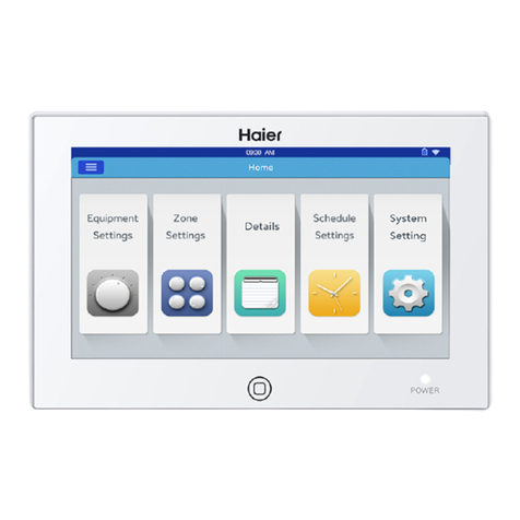
Haier YCZ-A004 User manual

Central Controller
Operation & Installation Manual
Please read this operation manual before using the air conditioner.
Please keep this manual carefully and safely.
YCZ-A004
CONTENT
Function introduction of central controller.................................................... 1
Part info for central controller ...................................................................... 3
Page & Key Explanation .............................................................................. 5
Address Setting When Using Central Controller ......................................... 7
System structure chart............................................................................... 13
Function Operation ....................................................................................15
Installation ................................................................................................. 36

Function introduction of central controller
1. YCZ-A004 can control MRV, single split and Supermatch. 256 indoor units can be controlled when used with MRV and
128 indoor units when with single split & supermatch.
When controlling MRV, YCZ-A004 should be used together with IGU05. One IGU05 is connected with one system of
At this situation, please set System Settings-Local-Type Selection-MRV.
When controlling single split units, every indoor unit needs to install one YCJ-A002, and all YCJ-A002s are connected
to YCZ-A004 hand by hand.
At this situation, please set System Settings-Local-Type Selection-Single Machine.
When controlling supermatch(or multi), every indoor unit needs to install one YCJ-A002, and all YCJ-A002s are
connected to YCZ-A004 hand by hand.
At this situation, please set System Settings-LOCAL-Type Selection-Multi.
2. Main functions of central controller
Monitoring and controlling indoor running state such as ON/OFF, Mode, Fan, Set temp. and error code.
Zone setting, editing and deleting.
Realizing ON/OFF, mode, fan, temperature setting for single/zone/all indoor unit(s).
Checking indoor unit detailed information such as real temperature, coil temperature, error code.
For MRV, three kinds of controlling mode: LIFO, Central & Force can be selected for indoor units; while only Force &
LIFO mode can be selected for single split unit.
LIFO: the indoor unit will execute the last order send by central controller, wired controller or remote controller. For
controller, the indoor unit will execute high fan.
Central: central controller enjoys all functions while wired &remote controller can only control ON/OFF of indoor units.
Force: central controller enjoys all functions while wired & remote controller cannot control indoor units.
Weekly timer setting. Weekly timer for one or some or all units can be set and can run in cycle.

Reset key:
Press to reboot central controller.
ON/OFF key:
After powering on, press this key to turn on controller and press for 3
seconds to turn off.
Display/touch screen:
Display and operation area.
Screensaver key:
Press to turn off screen light and press again to turn on.
Power light:
Power light will be on after powering on.
Part info for central controller

Fire alarm linkage contact
Power: 12V DC,
there is +- for power
Communication port for
connecting converter
Power (12V, GND): 12V DC, please pay attention to +-of power.
Fire alarm linkage contact (ALARM1, ALARM2): AC works normally when closed and all AC turned off when open circuit.
B1, A1: Reserved
Communication port (B2, A2): It is used for connecting converter, please pay attention to +-. A2 should be connected to
485+ while B2 485-.
Part info for central controller

Page & Key Explanation
After turning on central controller, home page will show as above and detailed menu is as following:
Menu/icon Function
AC detailed menu
POP will show after click the icon:
Online AC qty: indicating indoor unit quantity in
good communication.
in good communication previously and then in bad
communicaiton
AC qty set in timer: indicating AC quantity set timer
function
Error AC qty: indicating AC quantity in malfunction.
Equipment Settings Press to enter equipment setting interface and do
settings as follows:
Display all AC list and condition information. Turning
page for more information
AC mode can be checked and adjusted according to
zone/group. And application range can be selected and
it can realize All on/All off function.
Details
Click to enter details interface, in which, the following
information can be seen:
AC condition/mode condition, error code, running time &
parameters.
Weekly Timings Click to enter weekly timings interface, the following
setting can be operated:
After entering, it will display all weekly timing lists.
One or multi days in a week can be chosen for timing
setting.
Timer on/off, temperature, mode, fan, temperature
range(16-30°C), control mode, etc.
System Settings
Click to enter the interface, and the following setting can
be operated:
It includes Extra, Energy, Password and Local settings.
After clicking icon, relevant operations can be done.

Address Setting When Using Central Controller
When controlling MRV
When applying central controller, it is required to set address by dip switch for easy checking and maintenance.
For every system of AC, address starts from No. 1 to last indoor unit of the system. If totally 20 indoor units are connected in one
system, address should be 1-20; if 50 in one system, address should be 1-50; the biggest address is 64.
Note: every indoor address starts from 1.
1. Indoor address setting
The address used in central control or energy system
SW03 Central address
12345678
1 0 0 0 0 0 0 0 Central address=1
1 0 0 0 0 0 0 1 Central address=2
1 0 0 0 0 0 1 0 Central address=3
1 0 0 0 0 0 1 1 Central address=4
1 0 0 0 0 1 0 0 Central address=5
1 0 0 0 0 1 0 1 Central address=6
1 0 0 0 0 1 1 0 Central address=7
1 0 0 0 0 1 1 1 Central address=8
1 0 0 0 1 0 0 0 Central address=9
1 0 0 0 1 0 0 1 Central address=10
1 0 0 0 1 0 1 0 Central address=11
1 0 0 0 1 0 1 1 Central address=12
1 0 0 0 1 1 0 0 Central address=13
1 0 0 0 1 1 0 1 Central address=14
1 0 0 0 1 1 1 0 Central address=15
1 0 0 0 1 1 1 1 Central address=16
1 0 0 1 0 0 0 0 Central address=17
1 0 0 1 0 0 0 1 Central address=18
1 0 0 1 0 0 1 0 Central address=19
1 0 0 1 0 0 1 1 Central address=20
1 0 0 1 0 1 0 0 Central address=21
1 0 0 1 0 1 0 1 Central address=22
1 0 0 1 0 1 1 0 Central address=23
1 0 0 1 0 1 1 1 Central address=24
1 0 0 1 1 0 0 0 Central address=25
1 0 0 1 1 0 0 1 Central address=26
1 0 0 1 1 0 1 0 Central address=27
1 0 0 1 1 0 1 1 Central address=28
1 0 0 1 1 1 0 0 Central address=29
1 0 0 1 1 1 0 1 Central address=30
1 0 0 1 1 1 1 0 Central address=31
1 0 0 1 1 1 1 1 Central address=32
1 0 1 0 0 0 0 0 Central address=33
1 0 1 0 0 0 0 1 Central address=34
The address used in central control or energy system
SW03 Central address
12345678
1 0 1 0 0 0 1 0 Central address=35
1 0 1 0 0 0 1 1 Central address=36
1 0 1 0 0 1 0 0 Central address=37
1 0 1 0 0 1 0 1 Central address=38
1 0 1 0 0 1 1 0 Central address=39
1 0 1 0 0 1 1 1 Central address=40
1 0 1 0 1 0 0 0 Central address=41
1 0 1 0 1 0 0 1 Central address=42
1 0 1 0 1 0 1 0 Central address=43
1 0 1 0 1 0 1 1 Central address=44
1 0 1 0 1 1 0 0 Central address=45
1 0 1 0 1 1 0 1 Central address=46
1 0 1 0 1 1 1 0 Central address=47
Address Setting When Using Central Controller
1 0 1 0 1 1 1 1 Central address=48
1 0 1 1 0 0 0 0 Central address=49
1 0 1 1 0 0 0 1 Central address=50
1 0 1 1 0 0 1 0 Central address=51
1 0 1 1 0 0 1 1 Central address=52
1 0 1 1 0 1 0 0 Central address=53
1 0 1 1 0 1 0 1 Central address=54
1 0 1 1 0 1 1 0 Central address=55
1 0 1 1 0 1 1 1 Central address=56
1 0 1 1 1 0 0 0 Central address=57
1 0 1 1 1 0 0 1 Central address=58
1 0 1 1 1 0 1 0 Central address=59
1 0 1 1 1 0 1 1 Central address=60
1 0 1 1 1 1 0 0 Central address=61
1 0 1 1 1 1 0 1 Central address=62
1 0 1 1 1 1 1 0 Central address=63
1 0 1 1 1 1 1 1 Central address=64
0No need to add 64 to central
address Stay as 0
1 Add 64 to central address
0Central address set by wired
controller is available
1Central address set by wired
controller is unavailable Stay as 1

2. Converter address setting
1 2 3 4 5 6 7 8 Converter address
- - 0 0 0 0 0 0 1
- -000001 2
- -000010 3
- -000011 4
- -000100 5
- -000101 6
- -000110 7
- - 0 0 0 1 1 1 8
- - 0 0 1 0 0 0 9
- - 0 0 1 0 0 1 10
- - 0 0 1 0 1 0 11
- - 0 0 1 0 1 1 12
- - 0 0 1 1 0 0 13
- - 0 0 1 1 0 1 14
- - 0 0 1 1 1 0 15
- - 0 0 1 1 1 1 16
- - 0 1 0 0 0 0 17
- - 0 1 0 0 0 1 18
- - 0 1 0 0 1 0 19
- - 0 1 0 0 1 1 20
- - 0 1 0 1 0 0 21
- - 0 1 0 1 0 1 22
- - 0 1 0 1 1 0 23
- - 0 1 0 1 1 1 24
- - 0 1 1 0 0 0 25
- - 0 1 1 0 0 1 26
- - 0 1 1 0 1 0 27
- - 0 1 1 0 1 1 28
- - 0 1 1 1 0 0 29
Address Setting When Using Central Controller
- - 0 1 1 1 0 1 30
- - 0 1 1 1 1 0 31
- - 0 1 1 1 1 1 32
- - -- - - - - - Reserved
- - - - - -- - - Reserved

If one indoor unit is connected to IGU05 addressed as No. 1, and its central address is No. 6, the indoor code displayed on central
controller is 1-6; if one indoor unit is connected to IGU05 addressed as No. 5, and its central address is No. 20, the indoor code
displayed on central controller is 5-20.
Note: when controlling MRV, the YCZ-A004 can control max. 32 IGU05 and max. 256 indoor units. If IGU05 is more than 32 while
indoor quantity is less than 256, another YCZ-A004 is needed because IGU05 exceeds 32; If IGU05 is less than 32 while indoor
quantity is more than 256, another YCZ-A004 is needed because indoor quantity exceeds 256.
One indoor unit needs one converter YCJ-A002, YCJ-A002 addressing as follows:
When controlling single or multi split
SW01
[8] [7] [6] [5] [4] [3] [2] [1]
0 -- -- -- -- -- -- -- Single mode
1 -- -- -- -- -- -- -- Twin units shifting mode
-- 0 0 -- -- -- -- -- Shifting time 1—8 hours
-- 0 1 -- -- -- -- -- Shifting time 2—10 hours
-- 1 0 -- -- -- -- -- Shifting time 3—12 hours
-- 1 1 -- -- -- -- -- Shifting time 4—14 hours
-- -- -- 0 -- -- -- -- Twin units running mode when
-- -- -- 1 -- -- -- -- Twin units running mode when
Address Setting When Using Central Controller
-- -- -- -- 0 0 0 0 Central address in twin shifting
mode=1
-- -- -- -- 0 0 0 1 Central address in twin shifting
mode=2
---- ----
-- -- -- -- 1 1 1 0 Central address in twin shifting
mode=15
-- -- -- -- 1 1 1 1 Central address in twin shifting
mode=16
-- 0 0 0 0 0 0 0 Central address=1
-- 0 0 0 0 0 0 1 Central address =2
---- ----
-- 1 1 1 1 1 1 0 Central address =127
-- 1 1 1 1 1 1 1 Central address=128
YCZ-A004 can control at most 128 indoor units when controlling single or multi split.

System structure chart
1.System structure chart when controlling MRV:
One IGU05 is needed for one AC system, and max. 32 IGU05 can be connected to one YCZ-A004. When indoor unit total quantity is
less than 256, the IGU05 quantity connected to one YCZ-A004 cannot exceed 32; When IGU05 quantity is less than 32, the connected
indoor quantity cannot exceed 256.
2. System structure chart when controlling single split:
One YCJ-A002 is needed for every indoor unit. Max. 128 YCJ-A002 (as well as max. 128 indoor units) can be connected.

Function Operation
Equipment Settings
Press the “Equipment Settings” key on home page to enter the display interface as shown in picture 1.
is the return button. This button is always presented in the column, press this button to return to the last page.
means you can view air-conditioners as grouping established. Press “Zone” button to pop out all the air-conditioner grouped in
pop window.If air-conditioners have not been grouped before, it will show all air-conditioners.
Picture 1
Picture 2
Picture 3

Interface board face
Mode display
Set temperature
Wind speed display
Indoor unit address
is the All on/All off button. If it is displaying all indoor units, then the All on/All off button is used to control all indoor units; if it
is displaying the indoor units of one group, then the All on/All off button is used to control the indoor units in this group.
Each grid represents an indoor unit in the air-conditioner display area, and each page can display 10 indoor units. Slide around the
screen to turn pages on the screen.Indoor unit is shown as picture 4.
Picture 4
Record: The colors of upper part of the icon represents the operation modes, different mode uses different color to distinguish from
each other.
Heating Mode--orange;Cooling Mode--blue; Dry mode--aqua;
Fan mode--wathet;Intelligent Mode--wathet.
Press single air-conditioner icon to enter the air-conditioner setting interface, as shown in picture5
Function Operation
Picture 5
Setting interface:
Temperature setting: By sliding up/down the temperature selection area, you can change the setting temperature. It can be changed by
pressing arrow / too, press once to adjust it one time.
Record: In wind mode, the temperature will be gray and can’t be changed.
Set Mode: Press the corresponding mode icon, the setting is successful if the icon is lighted up. Only one mode can be chosen.
Set Wind Speed: Press the corresponding wind speed icon, the setting is successful if the icon is lighted up. Only one wind speed can
be chosen.
Record: If you choose the fan mode, you can’t choose the automatic wind speed any more.

Cooling Mode
Heating Mode Central Control
Dry Mode Locked
Intelligent Mode Low Speed
Wind Mode Automatically
High Speed
Medium Speed
Icon Instruction:
Batch change the air-conditioner mode setting: After setting one air-conditioner, press and pop window will pop out as shown
in picture 6.
Function Operation
Picture 6
If you choose “All”, then all indoor units will operate as ordered.
If you choose “indoor unit selection”, then the page will turn to interface displaying all indoor units, press the indoor unit icons to choose
the indoor units (the chosen ones will turn to dark color), they will operate as ordered.
operate as ordered.
Change the name of the air-conditioner:as shown in picture 7, press the air-conditioner number 1-2, then it will display the textbox
“please input device name” andclick the blank text boxto pop out the keyboard. After typing in the name, press “ENTER” to take back

Function Operation
layer, the corresponding air-conditioner icon name will also be refreshed.
Zone Settings
Picture 1
Picture 2
Press zone settings on the homepage to enter the zone setting interface, as shown in picture1.
It will display setting groups and adding new group button on the left. It will only display adding new group button initially. It will display
those air-conditioners which can be grouped. It will display all air-conditionersinitially.
Adding new group: press to pop out the window as shown in picture 2

Click the blank text box, enter the group name (up to 6 Chinese characters) by the keyboard, and press the“ENTER” button of the
keyboard after entering. Press OK key in the pop window to enter the interface as shown in picture3.
This interface displays air-conditioner numbers, click to choose those air-conditioners need to be added to grouping. It will turn to blue
after being selection, click again to cancel the selection.
For example: choose indoor units 1-1, 1-2, it will display as shown in picture 4.
Picture 3
Function Operation
Picture 4
Picture 5
Afterchoosing the air-conditioners, press
press again, it will display those air-conditioners which have not been grouped.
Press to return to the last layer when grouping air-conditioners.

In picture5, choose one group and then click button, it will pop out the pop window and it has three lines, as shown in picture6:
Edit group name: press the key to pop out the pop window of changing the group’s name.
Edit group’s dev: press the key to pop out the list of indoor units to edit the group’s dev.
Remove this group: pop out “to remove this group?” and press OK to delete the group, indoor units will come to “ungrouped”, press
“cancel” to come back to picture 5.
Picture 6
Function Operation
Press details button on homepage to enter detailed information interface as shown in picture1.
Vertical axis displays the name of the air-conditioner according to the order of the unit numbers, horizontal axis displays user name,
air-conditioner number, setting temperature, setting mode, setting wind speed, gas pipe temperature, liquid pipe temperature, expand
valve opening, operating time and faults information.
The progress bar is on the right and slide up and down within the progress bar to see all machine details.
After clicking , detailed information of indoor units in selected group can be checked.
Clicking to pop out password input window. Inputting password and click"Ok", all current date(except running time) will be
cleared. If clicking "Cancel", it will return to previous page.
Details
Picture 1

Weekly Timings
Choose Weekly Timingson the homepage to enter the initial schedule setting interface as shown in picture 1.
Press to add new schedule settings. Press this button to enter the setting interface, as shown in picture 2, “On”shows when the
machine starts up and “Off” shows when the machine shuts down.
Picture 1
Picture 2
Function Operation
Click the time text (such as 08:00 in picture 2) to pop out the window , choose the time of startup. Then set the temperature,
wind speed and mode.
Set the area applied to and weekly in the interface as shown in picture 3.
Click “Done” key after setting.
Picture 3

Apply Zone Settings:
For setting all users: Click to select all users
For setting individual user: Click the user selection textbox after all users to pop out the POP window, it will display all users, as
shown in picture 4.
Function Operation
Picture 4
Picture 5
Click the frame before the user’s indoor unit which you want to set, it will show a hook after selection.
Zone setting: click the zone to pop out the pop window as shown in picture 5, choosing it by clicking the frame before the area, you can
choose one or some of them.
the pop window as shown in picture 6.
Picture 6

Select those indoor units which you want to choose by clicking the frame before them, it will show hook after selection.
After setting the apply area, click blank area and pull-down lists will close.
Weekly:
From Monday to Sunday, it will show a hook after click, it will operate the schedule on the day you have chosen, it will circulate weekly.
It will display the setting schedule as shown in picture 7, ON/OFF time will be shown below the dial plate, press the dial to enter the
picture 2, you can adjust the setting time, fan speed and mode.
Function Operation
Picture 7
Picture 8
“On/Off”: setting the startup/shutdown of the schedule template.
Check the applied air-conditioners: click the “Apply to” below the schedule setting template, and you can check which indoor units are
applied by the schedule setting templateas shown in picture 8.
It displays the indoor units above.If there are too many indoor units, you can slide up and down to check them. It displays the weekly
cycle settings below.

system settings
It need password to enter setting page. Click “system settings” button on the home page, you will see the picture1 below.
Click login to enter system settings page after inputting password. System setting page includes 4 contents, as picture 2.
Extra
Picture 1
Picture 2
Function Operation
Mode setting: Click to choose model setting. It will show if you pitch on. Default is no limit.
Energy
As picture 3, 4
Picture 3
Other manuals for YCZ-A004
1
Table of contents
Other Haier Controllers manuals

Haier
Haier YR-E17A User manual

Haier
Haier HW-WA101DBT User manual

Haier
Haier YCZ-A004 User manual

Haier
Haier HW-BA101ABT User manual

Haier
Haier RWV05 V2 User manual

Haier
Haier YCZ-A001 User guide

Haier
Haier YR-E20 User manual

Haier
Haier QACT17A User manual

Haier
Haier QACT17A User manual

Haier
Haier QACT17A User manual
Popular Controllers manuals by other brands

Freescale Semiconductor
Freescale Semiconductor CPU32 Reference manual

ASE
ASE DS-7C installation manual

Inova Automation
Inova Automation NICE1000+ user manual

BB&S
BB&S Pipeline 4 Way Controller manual

Samsung
Samsung MCM-A202DN installation manual

SYCLOPE electronic
SYCLOPE electronic TERE'O Touch XL Installation and operating instructions