7. MAINTENANCE
Performing proper and periodical maintenance extends the product life. Efficient soldering depends upon
the temperature, the quality and quantity of the solder and flux. Apply the following service procedure as
dictated by the conditions of the usage.
WARNING
Since the handpiece tip/nozzle can reach a very high temperature, please work carefully. Except the case especially indicated,
always turn the power switch OFF and disconnect the power plug before performing any maintenance procedure.
1 Temperature
2. Cleaning
3. After use
4.
When the unit is not
being used and the
auto power shutoff
is not active.
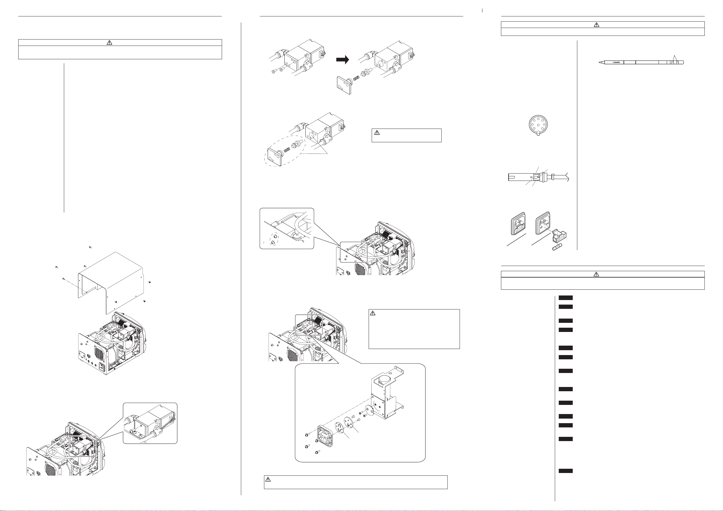
■Maintenance of the electromagnetic valve and pump head
●Remove the cover
When performing maintenance on either the electromagnetic valve or the pump head, remove the
screws holding the cover and take the cover off.
●Electromagnetic valve maintenance
1. Remove the screws holding the electromagnetic valve in place.
2. Remove the bottom of the electromagnetic valve.
3. Clean the parts that have flux attached to them, such as the inside of the electromagnetic valve, with
alcohol.
Clean with alcohol.
Caution
Do not use thinner when cleaning.
4. Assembly is done in the opposite order of disassembly.
*There is one more electromagnetic valve. Remove the screws on the back of the chassis, and from that
point on remove and clean following the same steps.
Remove
the screws.
●Cleaning the pump head
1. Remove the valve and valve guard and remove any attached flux.
Caution
・When the valve guard is difficult to remove,
please warm it with hot air. Please do not try
to forcibly remove it with a screwdriver, etc.
If the valve guard becomes deformed, it will
no longer be airtight.
・Please clean with either alcohol or thinner.
2. Install the valve and valve guard.
Caution
When assembling the pump, please make sure to keep it airtight so that there are no air leaks.
8. CHECKING PROCEDURE
Measure the resistance across this position.
1
4
7
2
8
5
6
3
■Check for a broken heater or
sensor
■Check the grounding line
1. Check for a broken heater or sensor
Verify the electrical integrity of the heater and sensor.
Measure the resistance of the heater and sensor while at room
temperature(15〜25℃;59〜77℉). It should be 8 Ω±10%. If
the resistance exceeds these limits, replace the tip.
1. Unplug the connection cord from the station.
2. Measure the resistance value between Pin 2 and the tip.
3. If the value exceeds 2 Ω(at room temperature), perform the
tip maintenance described on section 2, maintenance for the
tip. If the value still does not decrease, check the connection
cord for breakage.
WARNING
Unless otherwise directed, carry out these procedures with the power switch OFF and the power UNPLUGGED.
Black
White
Green Red
■Checking the connection cord
for breakage (HAKKO FM-2027)
■Replacing the fuse
1. Remove the soldering tip and the sleeve assembly.
2. Turn the front piece of the HAKKO FM-2027 counterclockwise
and remove the cover.
3. Measure the resistance values between the connector and the
lead wires at the socket as follows:
Pin 1 – Red Pin 2 – Green
Pin 3 – Black Pin 5 – White
If any value exceeds 0 Ωor is ∞, replace the HAKKO FM-2027.
1. Unplug the power cord from the power receptacle.
2. Remove the fuse holder.
3. Replace the fuse.
4. Put the fuse holder back in place.
High temperatures shorten tip life and may cause thermal shock to components.
Always use the lowest possible temperature. The excellent thermal recovery
characteristics of the HAKKO FM-206 ensure effective soldering at low
temperatures.
Always clean the tip/nozzle before use to remove any residual solder or flux
adhering to it. Use the tip cleaner or cleaning sponge. Contaminants on the tip
have many deleterious effects, including reduced heat conductivity, which
contribute to poor performance.
Always clean the tip/nozzle and coat it with fresh solder after use. This guards
against oxidation.
This procedure, if followed daily, will materially add to tip life.
a. Set the temperature to 250℃(482℉).
b. When the temperature stabilizes, clean the tip and check the condition of the
tip. If the tip is badly worn or deformed, replace it.
c. If the solder plated part of the tip is covered with black oxide, apply fresh
solder, containing flux, and clean the tip again. Repeat until all the oxide is
removed, then coat the tip with fresh solder.
d. Turn the power OFF and remove the tip, using the heat resistant pad. Set the
tip aside to cool.
e. Remaining oxides, such as the yellow discoloration on the tip shaft, are not
harmful but can be removed with isopropyl alcohol.
Never allow the unit to idle at a high temperature for extended periods. This will
allow the tip to become oxidized. Turn the power switch OFF. If it is to be out of
service for several hours, it is advisable to pull the power plug as well.
Valve
Valve guard
Clean the pump head, valve
and valve guard.
Pump head disassembly
*It is resting on its side.
*Please replace the valve if it is
deformed or hardened.
Pump head
CHECK
: Is the power cord and/or the connection plug disconnected?
ACTION
: Connect it.
CHECK
: Is the fuse blown?
ACTION
: Replace the fuse. If the fuse blows again, send the unit in for repair.
CHECK
: Is the tip inserted properly?
ACTION
: Insert the tip completely.
CHECK
: Is the connection cord and/or the heater/sensor broken?
ACTION
: If the cord assembly is broken, replace the soldering iron, desoldering tool or
handpiece.
CHECK
: Is the tip temperature too high?
ACTION
: Set the appropriate temperature.
CHECK
: Is the tip contaminated with oxide?
ACTION
: Remove the oxide
CHECK
: Is the connection cord broken?
ACTION
: If the cord assembly is broken, replace the soldering iron, desoldering tool or
handpiece.
CHECK
: Is the tip contaminated with oxide?
ACTION
: Remove the oxide
CHECK
: Is the handpiece connected?
ACTION
: Remove and reinsert the handpiece.
CHECK
: Is the tip too small for the items to be soldered?
ACTION
: Use a tip with a larger thermal capacity.
CHECK
: Is the setting value for the low-temperature alarm tolerance too low?
ACTION
: Increase the setting value.
CHECK
: Is the appropriate HAKKO tip/nozzle being used?
ACTION
: Turn the power switch OFF and insert the genuine HAKKO tip/nozzle. Turn the
power switch ON.
ACTION
: Turn the power switch OFF and insert the genuine HAKKO tip. Turn the power
switch ON.
CHECK
: Is the tip left on the wet cleaning sponge?
ACTION
: Turn the power switch off. Turn the power switch on again after removing the
tip from the wet cleaning sponge.
ACTION
: Turn off the power switch. Turn on the power switch again.
If the “Zero-Cross Error” / “System Error” continues to be displayed after
turning on the power switch, contact your HAKKO representative.
9. TROUBLE SHOOTING GUIDE
WARNING
BeforecheckingtheinsideoftheHAKKOFM-206orreplacingparts,besuretodisconnectthepower
plug.Failuretodosomayresultinelectricshock.
●The unit does not operate
when the power switch is
turned on.
●The tip does not heat up.
“Sens Error” is displayed.
●Solder does not wet the tip.
●The tip temperature is too
high.
●The tip temperature is too
low.
●“Grip Error” is displayed.
●The low-temperature alarm
tolerance error “Low Temp”
is displayed.
●
Heater terminal short circuit
error “Heater Short Error” is
displayed.
●“Heat up Error” is displayed.
(for MODEL FM-2023)
●“Drive Error” is displayed.
(for MODEL FM-2023)
●“Zero-Cross Error” or
“System Error” is displayed.