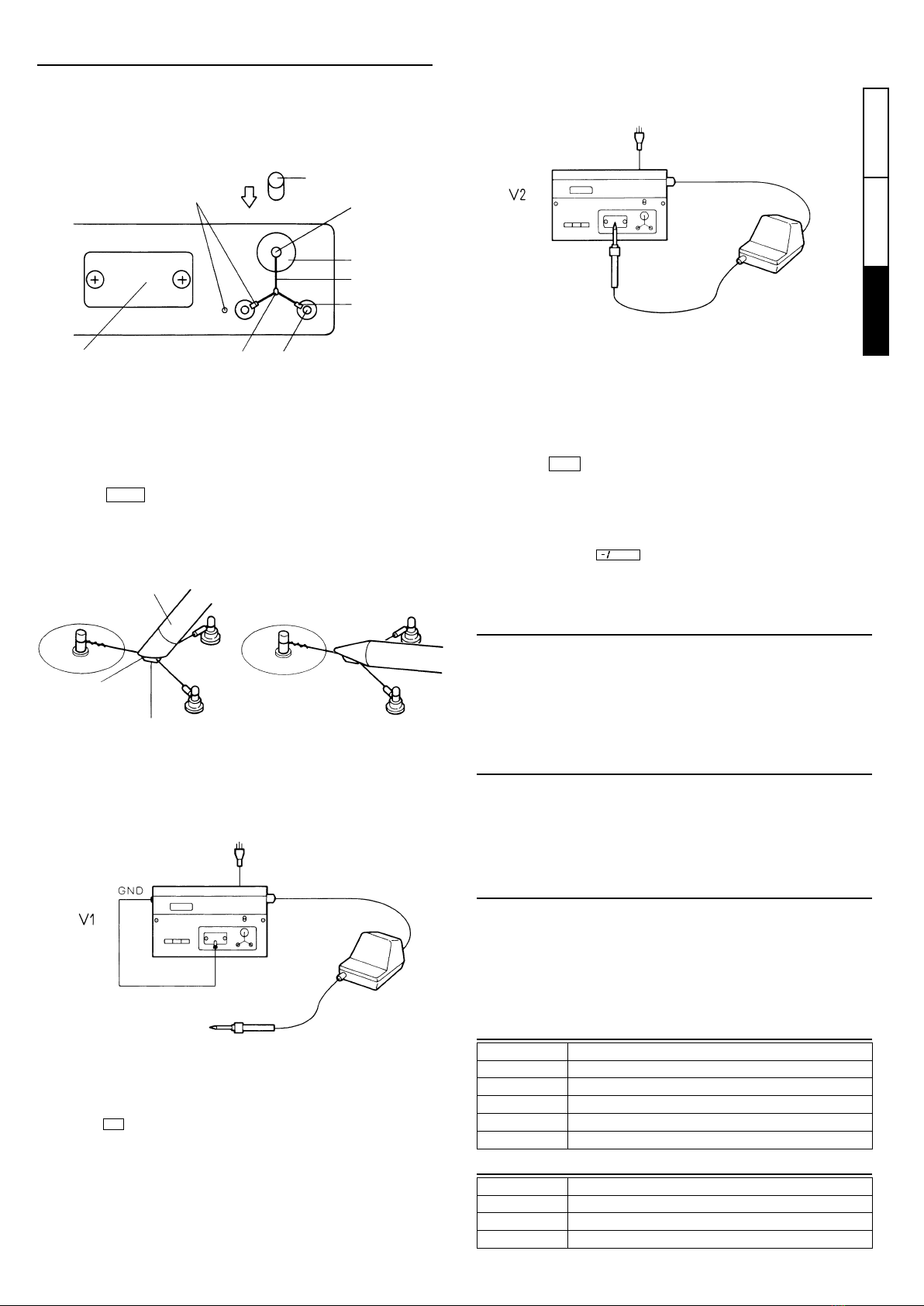
manuals.online logo
Brands
  1. Home
  2. •
  3. Brands
  4. •
  5. Hakko Electronics
  6. •
  7. Test Equipment
  8. •
  9. Hakko Electronics 192 User manual

Hakko Electronics 192 User manual

English
中 文日本文
1
はんだこてテスター
このたびは、ハッコー192をお買い求めいただきまことにありがとうございます。ご使
用になる前に必ず本書をお読みください。また、大切に保存しておいてください。
本機は、こて先を接地していないはんだこてには使用できません。
本機は、アース端子を備えたコンセントに接続し、接地してご使用ください。
※仕様及び外観は改良のため予告なく変更することがありますが、あらかじめご了承ください。
取扱説明書
■セット内容
ハッコー192・・・・・・・・1
温度センサー・・・10ヶ
取扱説明書
リング板・・・・・・・・・・・・・1
グラウンドクリップ
ミゼットヒューズ(5A)
伝導ワイヤー
■使用上の注意
■仕様
ミゼットヒューズ(5A)
グラウンドクリップ
表示部
伝導ワイヤー
電源コード
電源プラグ
コンセント
ヒューズ
 ホルダー
電源スイッチ
伝導プレート
セレクトスイッチ
モニター出力
グラウンド端子
■各部名称
温度センサーは非常に細い(φ 0.2)
ため、強く押すと切れる恐れがあり
ます。丁寧にお取扱いください。
温度センサーの測温部には、特殊処
理を施してありますが、測定を繰り
返すうちに劣化してきます。正確な
温度を出すため、早めに交換してく
ださい。
ターミナルにフラックスが付着し
た場合は、アルコールで拭き取って
ください。シンナーやベンジンはご
使用にならないでください。
測定時には、こて先に新しいはんだ
をのせてください。温度センサーま
たは、伝導プレートとこて先の接触
を確実にするために必要です。
1.
2.
3.
4.
5.
6.
7.
電圧測定時、伝導プレートにこて先
をあてないとき、オーバーレンジ表
示にならずに数値が表示されるこ
とがございますが、故障ではありま
せん。
電圧、抵抗の測定時は、本体電源コ
ードは必ず、接地された二極接地型
コンセントに接続してください。
電圧、抵抗測定の結果が規定以上の
値が出たときは、はんだこてのこて
先や取付ネジのゆるみなどを確認し、
再度測定してください。
192-1
分解能
測定範囲
測定許容差
センサー
分解能
測定範囲
測定許容差
MIL-STD-2000 準拠
分解能
測定範囲
測定許容差
液晶(LCD)表示
オーバーレンジ
温度
電圧
抵抗
バーンアウト
AC100V 50/60Hz
1W
200(W)×50(H)×120(D)mm
約 1.1kg
0 〜 40℃、20 〜 90%RH、結露無きこと
1℃
0〜600℃
±3℃(300〜500℃の範囲)
K(CA)熱電対
0.1mV
0〜90mV(AC)
±(5% of reading + 1 digit)
0.1Ω
0〜90Ω
±(5% of reading + 1 digit)
3  /
2
桁
1mV/℃
10mV/mV
10mV/Ω
−7V(最大)
品番
温度
電圧
抵抗
表示
モニター出力
定格
消費電力
外形寸法
重量
動作環境
1
・・1
・・・・・・・・・1
・・1
・・・・・・・1
リング板
中 文 日本文
English
2
赤色
スライドボタン
スライド棒
リング板
センサー
青色
ターミナル
こて先
新しいはんだ
測温部
アース付コンセント
コンセント
グラウンドクリップ
測温部
■モニター出力
192は測定結果を直流電圧に変換してモニター出力端子より出力しています。出
力電圧は「仕様」をご覧ください。
モニター出力は、測定結果を直流電圧に変換するため、本体表示値とは一致しな
いことがあります。また、出力先となる測定器の誤差もありますので、モニター
出力のご使用にあたってはご注意ください。
●
●
■グラウンド端子(GND)
グラウンド端子(GND)は192本体コンセントのグラウンド(アース)ラインに接
続されています。こて先 - アース間の電位差および、こて先 - アース間の抵抗を
測定する際に、V1、R1を求めるために使用します。
測定するはんだこてがワニ口クリップなどで接地するタイプの場合は、このグ
ラウンド端子に、グラウンドクリップで接続してください。
●
●
■メンテナンスと校正
■交換部品
伝導プレートの交換は、取付ネジを外して行ってください。
温度センサーの寿命は使用する温度やはんだ、フラックスの成分によって変わ
ります。50 回程度をめやすとして、測温部が消耗したら交換してください。
校正は弊社が有償にて承ります。本機をお求めになった販売店、代理店にお申し
付けください。
品番
191-212
B1752
B1754
B1950
B2705
品名
温度センサー(K熱電対)10ヶ入り
伝導プレート
グラウンドクリップ
伝導ワイヤー
ミゼットヒューズ/125V-5A
●
●
●
 ■測定方法
 ①準 備
1. リング板をスライド棒に取り付けます。
2. スライドボタンを矢印方向に押して、センサーを図の方向(センサーと本
 体の赤色をあわせ、反対側のターミナルに青色)に取り付けます。
8.伝導プレートの中央部にはんだを盛り、良好なはんだヌレが形成されるまで加
熱します。
9.表示が安定したら読み取ります。(V2)
②こて先温度の測定
③こて先-アース間の電位差
1.セレクトスイッチ を押します。
2.こて先をクリーニングして、新しいはんだをのせます。
3.すばやくこて先を温度センサーの測温部に、正確にあてます。
④こて先-アース間の抵抗
1.セレクトスイッチ を押して、「こて先 - アース間の電位差」の測定と同
じ要領で、R1、R2、を測定します。
2.こて先 - アース間の抵抗(R)を R = R2− R1で求めます。
⑤オーバーレンジ表示
1.測定するはんだこての電源プラグを、192本体のコンセントに差し込みます。
2.こて先が設定温度、または、設定温度を可変できるタイプは、最高温度に設定し
最高温度に到達するのを待ちます。
3.セレクトスイッチ を押します。
4.グラウンドクリップで192本体のグラウンド端子(GND)と伝導プレートを接続
します。
5.表示を読み取ります。(V1)
6.グラウンドクリップを外します。
7.こて先をクリーニングして、新しいはんだをのせます。
●必ずアース端子を備えたコンセント
に接続してください。
●192 本体のコンセントは、電源スイ
ッチが入っているときだけ電気が供
給されます。
3.電源プラグをコンセントに差し込み、電源スイッチを入れます。
10.こて先 - アース間の電位差(V)を V = V2− V1で求めます。
※その他、校正も承ります。
4.表示温度が上昇していきますので、安定するまでお待ちください。
(およそ2〜3秒)
TEMP
OHM
交換方法
mV
図のようにこて先の形状に合わせて、
測温部をはんだ付けするようなつも
りであててください。
オーバーレンジ表示は、温度測定時に温度センサーが取り付けられていないとき、電圧、抵抗測定
時、伝導プレートにこて先をあてていないときにも表示されます。
こての電源プラグが3ピンではなく、
ワニ口クリップなどの場合、グラウ
ンドクリップで GND 端子に接続し
て、測定します。
※熱容量の小さいこて先で、こて先温度が低いなど伝導プレートでははんだが溶
けにくい場合は、付属の伝導ワイヤーをご使用ください。なお、伝導プレートは
MIL-STD-2000 に準じて作られておりますので、上記の場合以外は伝導プレー
トをご使用ください。
伝導プレートを取り付けているネジを2本はずし、伝導プレートを伝
導ワイヤーに交換後、はずしたネジで取り付けてください。
■オプション
品番
191-212C
A1310
B1753
C1220
品名
温度センサー(K熱電対)10ヶ入り 校正表付
温度プローブ(はんだ槽用)
モニターコード
温度プローブ(自動機用)
伝導プレート
3
紅色
滑鈕
滑桿
環板
傳感器
藍色
終端
焊鐵頭
新焊錫
測試點
接地插頭
插座
接地夾
測試點
■監視器輸出
HAKKO192 能將測試轉換為直流電壓值 , 並將這些電壓值從監視器輸出終端輸出。
請參閱前頁所述電壓值 " 規格 " 表。
應小心使用監視器輸出。由於測試轉換為直流電壓值 , 監視器輸出可能與顯示器
所顯示者不同 , 而且輸出這些電值的儀器本身也有一些差誤。
●
●
■接地終端(GND)
HAKKO192 焊鐵的接地線是用於連接接地終端 (GND) 。當測試焊鐵頭和接地之間
的電勢和電阻差別 , 以求取 V1 和 R1 電值時便要使用接地終端。
如使用鱷夾接地的焊鐵時 , 應將鱷夾連接接地終端 (GND) 。
●
●
■保養和校準
■更換部件
更換導電板時 , 要鬆脫螺絲。
溫度傳感器使用壽命之長短 , 胥視所測試溫度之高低 , 以及所使用的焊錫和助焊劑
而定。一般而言 , 溫度傳感器可測試 50 次。測試點耗損時 , 應更換傳感器。
HAKKO192 於有代價可校準。詳細情況請聯係您購買之代理店。
編號
191-212
B1752
B1754
B1950
B2705
名稱
溫度傳感器(10個)
導電板
接地夾
傳導線
Midzet保險絲(125V-5A)
●
●
■程序
1. 準備
1.將環板緊貼在滑桿上。
2.按下圖箭頭所示方向移動滑鈕 , 然後如圖示連接傳感器 ( 紅端連接誌有紅點終端 ,
藍端連接藍點終端 ) 。
8.放置一小點焊錫在導電板中心 , 然後至到錫點完全溶化為止。
9.當顯示屏穩定時 , 閱讀電值 (V2) 。
2. 測試焊鐵頭溫度
3. 測試焊鐵頭和接地之間的電勢差別。
1.按下 ( 溫度 ) 選擇掣。
2.清理乾淨焊鐵頭並鍍上新焊錫。
3.立刻將焊鐵頭置放在溫度傳感器的測試點上。參考下圖根據所使用焊鐵頭款型 ,
將焊鐵頭貼切置放在
測試點上 , 正如進行焊接那一點。
4. 測試焊鐵頭和接地之間的電阻
1.按下 選擇掣 , 程序一如測試電勢差別。測試 R1 和 R2 電阻值
( 類似 V1 和 V2) 。
2.將 R2 減去 R1, 便得出焊鐵頭和接地之間的差別。 R=R2-R1
5. 超出範圍顯示
1.將測試的焊鐵臺之電源插頭插入 HAKKO192 插座。
2.等候焊鐵頭昇溫到設定溫度。如果焊鐵是選用可變更溫度的焊鐵頭款型 , 應將溫
度設定在最高溫度。
3.按下 ( 毫伏 ) 選擇掣。
4.利用接地夾連接 HAKKO192 接地終端和導電板。
5.閱讀顯示屏 (V1) 電值。
6.取下接地夾。
7.清理乾淨焊鐵頭並鍍上新焊錫。
●
確保插頭插入接地 (3 孔 ) 插座。
●
當 HAKKO192 插入電源並通電時 , 電
流便輸入測試儀。
3.將插頭插入電源插座 , 按開電掣。
10.將 V2 減去 V1, 便得出焊鐵頭和接地之間的差別。 V=V2-V1
超出範圍符號為 。
4.測試儀所顯示的電值將會昇高 , 等候 2 ∼ 3 秒鐘待穩定下來。
TE MP
O H M
更換方法
mV
測試溫度時 , 如果未連接傳感器便發生超出範圍現象。
測試電壓和電阻時 , 如果焊鐵頭未連接導電板也發生超出範圍現象。
如果焊鐵電源插頭是鱷夾型而不是 3
腳型接地插頭 , 應將接地夾連接接地
終端 , 然後測試。
注 :導電板是符合 MIL-STD-2000 規格而製造的。
 因此除了上述情況以外 , 請使用導電板。
1. 解開裝置在導電上的兩個小螺釘。 2. 解開導電板。 3. 更換導電板後 ,
再裝回小螺釘。
■另購配件
編號
A1310
B1753
C1220
名稱
適用於測量錫爐溫度探針
監視器電線
適用於測量自動機器溫度探針
English
中 文日本文
5
導電板
●
6
中 文 日本文
English
*Specifications and design are subject to change without notice.
Instruction Manual
■ Packing List
HAKKO 192 1
Temperature sensors 10
Ring plate 1
Ground clip 1
Midzet fuse (5A) 1
Conduction wire 1
Instruction manual 1
■ Precautions
■ Specifications
Midzet fuse (5A)
Ground clip
Display
Conduction wire
Power cord
Power plug
Receptacle
Fuse holder
Power switch
Conduction plate
Select switches
Monitor
output
Ground
terminal
■ Part Names
Handle the temperature sensor carefully. The temperature sensor is
extremely thin ø0.2 and may break if pressed with too much force.
The measuring point on the temperature sensor has been specially
processed, but repeated measurements will cause it to wear out. Replace
it promptly to ensure the accuracy of measurements.
When there is flux on the terminal, wipe it away with a cloth that has been
moistened with alcohol. Do not use paint thinner or benzene.
Before measuring, coat the soldering iron tip with fresh solder. This is
necessary to ensure proper contacting between the tip, the temperature
sensor, and the conduction plate.
Instead of the over range code –1 , a value will sometimes be displayed
when the tip is not touching the conduction plate during voltage
measurement. This is normal.
During voltage and resistance measurement, make sure that the power
cord has been inserted into a grounded (3-hole) outlet.
When voltage and resistance measurements are greater than the
prescribed values, check the tip and make sure the fastening screws of
soldering iron are not loose, then measure again.
1.
2.
3.
4.
5.
6.
7.
Resolution
Measurement range
Precision
Sensor
Resolution
Measurement range
Accuracy
Conforms to MIL-STD-2000
Resolution
Measurement range
Accuracy
Liquid crystal display (LCD)
Over range
Temperature
Voltage
Resistance
Burn out
1W
200 (W) 50 (H) 120 (D) mm
7.9 (W) 2.0 (H) 4.7 (D) in.
Approx.1.1 kg/2.4 lbs.
0 to 40°C (32 to 104°F), 20 to 90% RH, no dew
1°C/1°F
0 ~ 600°C/0 ~ 1200°F
±3°C (in 300 ~ 500°C range)
±6°F (in 572 ~ 932°F range)
K (CA) thermocouple
0.1 mV
0 ~ 90 mV (AC)
±(5% of reading + 1 digit)
0.1
0 ~ 90
±(5% of reading + 1 digit)
3 /
2
digits
1 mV/°C, °F
10 mV/mV
10 mV/
-7 V (max.)
Temperature
Voltage
Resistance
Display
Monitor output
Power consumption
Dimensions
Weight (w/o cord)
Operating environment
Thank you for purchasing the HAKKO 192 soldering tester.
Please read this manual before operating the HAKKO 192.
Keep this manual readily accessible for reference.
The HAKKO 192 cannot be used with ungrounded soldering irons.
Ground the soldering iron by plugging it into a grounded (3-hole)
outlet.
1
Ring plate
中 文日本文 English
7
Red
Slide button
Slide pole
Ring plate
Sensor
Blue
Terminal
Tip
Fresh solder
Measuring point
Grounded outlet
Receptacle (for soldering iron)
Ground clip
Measuring point
■Monitor Output
The HAKKO 192 converts the measurements to DC voltage values and
outputs these values from the monitor output terminal. See the
"Specifications" table on the previous page for voltage values.
Be careful when using monitor output; as measurements are converted to
DC voltage values, monitor output may not match the values shown on the
display. There will also be some error on the part of the instrument to
which these values are output.
●
●
■Ground Terminal (GND)
The ground terminal (GND) is connected to the ground line for the
soldering iron outlet on the HAKKO 192. It is used when deriving the
values for V1 and R1 during measurement of the difference in potential
and the resistance, respectively, between the tip and ground.
When using a type of soldering iron that is grounded with an alligator clip,
connect the clip to the GND terminal.
●
●
■Maintenance and Calibration
■Replacement Parts
To replace the conduction plate, remove the set screws.
The life of the temperature sensor will vary depending on the temperature
at which measurements are made and the type of solder and flux being
used. In general, temperature sensors can be used for 50 measurements.
Replace the sensor as soon as the measuring point wears out.
HAKKO can calibrate the instrument for a nominal fee. Please contact
your dealer for further information.
Part No.
191-212
B1752
B1754
B1950
B2705
Part Name
Temperature sensors (10 pcs.)
Conduction plate
Ground clip
Conduction wire
Midzet fuse (5A)
●
●
●
■ Procedure
①Preparations
1. Attach the ring plate to the slide pole.
2. Move the slide button in the direction indicated by the arrow in the figure
below, then attach the sensor as shown in the drawing (place the red end
on the side with the red dot, and blue end on the other side of the
terminal).
3. Insert the power plug into the outlet and turn the power switch on.
●Be sure to insert the power plug into a grounded (3-hole) outlet.
●Power will be supplied to the outlet on the HAKKO 192 only when the
unit is plugged in and the power switch is turned on.
9. When the display has stabilized, read the value. (V2)
If the soldering iron power plug uses an alligator clip rather than a 3-
prong grounded plug, connect it to the GND terminal with the ground clip
and then perform measurements.
10. Subtract V1 from V2 to derive the difference in potential between
the tip and the and the ground.
V = V2 - V1
②Measuring the tip temperature
③Measuring the difference in potential between tip
and ground
1. Press the select switch.
2. Clean the tip and coat it with fresh solder
3. Quickly place the tip on the measuring point on the temperature sensor.
As shown in the figure below, place the tip properly on the measuring
point in accordance with the type of tip being used, as if you were
soldering that point.
4. The value shown in the display will increase; wait two (2) to three (3)
seconds for it to stabilize.
④Measuring the resistance between tip and ground
1. Press the OHM select switch. Using the same procedure as when
measuring the difference in potential, measure the values for R1 and R2
(which correspond to V1 and V2 in that procedure).
2. Subtract R1 from R2 to derive the resistance between the tip and
ground. R = R2 - R1
⑤Over range display
1. Plug in the soldering iron by inserting the plug on the power cord into the
receptacle on the HAKKO 192.
2. Wait until the tip reaches the set temperature. If the soldering iron is a
variable tip temperature model, set temperature to the maximum.
3. Press the mV select switch.
4. Using the ground clip, connect the ground terminal (GND) on the HAKKO
192 to the conduction plate.
5. Read the value on the display. (V1)
6. Disconnect the ground clip.
7. Clean the tip and coat it with fresh solder.
8. Place a tiny bead of solder in the center of the conduction plate and heat
the bead until the solder has completely melted.
TEMP
The over range code is . An over range occurs during temperature
measurement when the temperature sensor is not attached, and during
voltage and resistance measurement when the tip is not in contact with the
conduction plate.
Note:
When using fine tips at low temperatures and the solder is hardly melted
on the conduction plate, use the attached conduction wire. Measuring
with conduction plate meets MIL standard; always use the conduction
plate except for the above written cases.
1. Remove the two (2) screws which secure the conduction plate.
2. Remove the conduction plate.
3. Secure the conduction wire with the same screws in place of the
conduction plate.
■Optional Parts
Part No.
A1310
B1753
C1220
Part Name
Temperature probe (for soldering pot)
Monitor cord
Temperature probe (for automatic machine)
Conduction plate
〒556-0024 大阪市浪速区塩草2丁目4番5号
TEL:(06)6561-1574(代)FAX:(06)6568-0821
http://www.hakko.com
2005. 9
MA0124XZ050902
OVERSEAS AFFILIATES
U.S.A.: AMERICAN HAKKO PRODUCTS, INC.
TEL: (661) 294-0090 FAX: (661) 294-0096
Toll Free (800)88-HAKKO
4 2 5 5 6
http://www.hakkousa.com
HEAD OFFICE
TEL:+81-6-6561-3225 FAX:+81-6-6561-8466
http://www.hakko.com E-mail:[email protected]
HONG KONG: HAKKO DEVELOPMENT CO., LTD.
TEL: 2811-5588 FAX: 2590-0217
http://www.hakko.com.hk
E-mail:[email protected]
SINGAPORE: HAKKO PRODUCTS PTE., LTD.
TEL: 6748-2277 FAX: 6744-0033
http://www.hakko.com.sg
E-mail:[email protected]
Please access to the following address for the other Sales affiliates.
http://www.hakko.com

Other Hakko Electronics Test Equipment manuals

Hakko Electronics FG-470 User manual

Hakko Electronics

Hakko Electronics FG-470 User manual

Hakko Electronics FG101-16 User manual

Hakko Electronics

Hakko Electronics FG101-16 User manual

Hakko Electronics FG-470 User manual

Hakko Electronics

Hakko Electronics FG-470 User manual

Hakko Electronics FR-410 User manual

Hakko Electronics

Hakko Electronics FR-410 User manual

Hakko Electronics FR-811 User manual

Hakko Electronics

Hakko Electronics FR-811 User manual

Hakko Electronics FG-460 User manual

Hakko Electronics

Hakko Electronics FG-460 User manual

Hakko Electronics FG101B-03 User manual

Hakko Electronics

Hakko Electronics FG101B-03 User manual

Hakko Electronics FG-465 User manual

Hakko Electronics

Hakko Electronics FG-465 User manual

Hakko Electronics FG-101B User manual

Hakko Electronics

Hakko Electronics FG-101B User manual

Hakko Electronics FG-101 User manual

Hakko Electronics

Hakko Electronics FG-101 User manual

Popular Test Equipment manuals by other brands

National Instruments PXIe-5160 Getting started guide

National Instruments

National Instruments PXIe-5160 Getting started guide

JONARD TOOLS TETP-900 instruction manual

JONARD TOOLS

JONARD TOOLS TETP-900 instruction manual

aci GP Series Installation & operation instructions

aci

aci GP Series Installation & operation instructions

multicomp pro MP720009 manual

multicomp pro

multicomp pro MP720009 manual

Atec gigaBERT1400 user manual

Atec

Atec gigaBERT1400 user manual

Time Electronics 5051 Plus user manual

Time Electronics

Time Electronics 5051 Plus user manual

M&C PSS Series instruction manual

M&C

M&C PSS Series instruction manual

Agilent Technologies 1100 Series user guide

Agilent Technologies

Agilent Technologies 1100 Series user guide

Levenhuk Ermenrich Ping SM80 user manual

Levenhuk

Levenhuk Ermenrich Ping SM80 user manual

Maschinenfabrik Reinhausen TAPCON 260 operating instructions

Maschinenfabrik Reinhausen

Maschinenfabrik Reinhausen TAPCON 260 operating instructions

GAIN EXPRESS NF-838 instruction manual

GAIN EXPRESS

GAIN EXPRESS NF-838 instruction manual

PCE Instruments PCE-789 manual

PCE Instruments

PCE Instruments PCE-789 manual

iqualitrol iVick-472H instruction manual

iqualitrol

iqualitrol iVick-472H instruction manual

EXFO ConnectorMax MFS-12 Quick reference guide

EXFO

EXFO ConnectorMax MFS-12 Quick reference guide

Tektronix 2336YA instruction manual

Tektronix

Tektronix 2336YA instruction manual

Kewtech KT63DL operating instructions

Kewtech

Kewtech KT63DL operating instructions

SENTRONIC M-SYSTEM M6D Series instruction manual

SENTRONIC

SENTRONIC M-SYSTEM M6D Series instruction manual

OTC Tools 3182 operating instructions

OTC Tools

OTC Tools 3182 operating instructions

manuals.online logo
manuals.online logoBrands
  • About & Mission
  • Contact us
  • Privacy Policy
  • Terms and Conditions

Copyright 2025 Manuals.Online. All Rights Reserved.