3
3. Safety and Handling Precautions
This document divides precautions into the following two categories, "WARNING" and
"CAUTION."
Fully understand the content of the precautions below before reading descriptions in this
document.
WARNING : This indicates that mishandling might lead to death or serious injury.
CAUTION : This indicates that mishandling might lead to injury or damage to property.
Note : This indicates procedures or information that are important in a process
described in this document.
Be sure to observe the following precautions to ensure safety.
WARNING
●Those without the permission of a manager and those without the required
experience or knowledge (including children) are not allowed to use this product.
●Do not allow children to play with this product.
●Do not allow children to clean or perform user maintenance without supervision.
Failure to observe the following precautions to ensure safety might result in electric shock,
malfunction or other trouble.
CAUTION
●Before using this product, fully read all descriptions in this document.
●
During measurement with this product, a trace amount of current flows to the human body.
People with a weak heart or those using a cardiac pacemaker should not use this product.
●Users that are pregnant, please consult with the proper medical specialist.
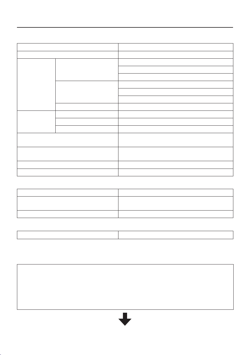
Current flowing through human body:
2 to 3 μA approx. (reference value (measurement
on the antistatic shoes: 20 MΩ))
Current flowing through human body: 50 to 100 μA (measurement on bare feet)
●
Wearing thick socks with anti-static footwear may adversely affect the measurement result.
In addition, when performing measurement, correctly wear anti-static footwear in
accordance with the designated instructions.
●
The installation base is also used with the optional exclusive stand. Be sure to store this
base in a safe place.
●
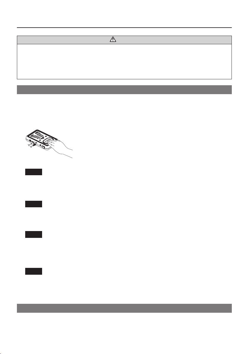
Do not subject this product to strong impact. Do not tap or push on the pad with strong force.
●This product is for indoor use only. Do not use it outdoors.
●When discontinuing or stopping use of this product or when moving away from where
this product is mounted, turn it OFF.
●When this product is not used for a long time, or before repairing or cleaning this product,
disconnect the AC adapter plug from the power outlet.
●When replacing parts, use only genuine HAKKO parts.
●Use only the AC adapter that is included in the set. Do not use other AC adapters.
●Do not modify this product.
●Do not use this product with damaged cords or plugs.
Also, if this product malfunctions, is dropped or is damaged in other ways, immediately
stop use of this product.
●When inserting and removing the plug, hold the plug body and do not pull the cord.
●Do not allow this product to get wet. Also, do not handle it with wet hands.
●Do not perform any other actions that may be considered to be dangerous.