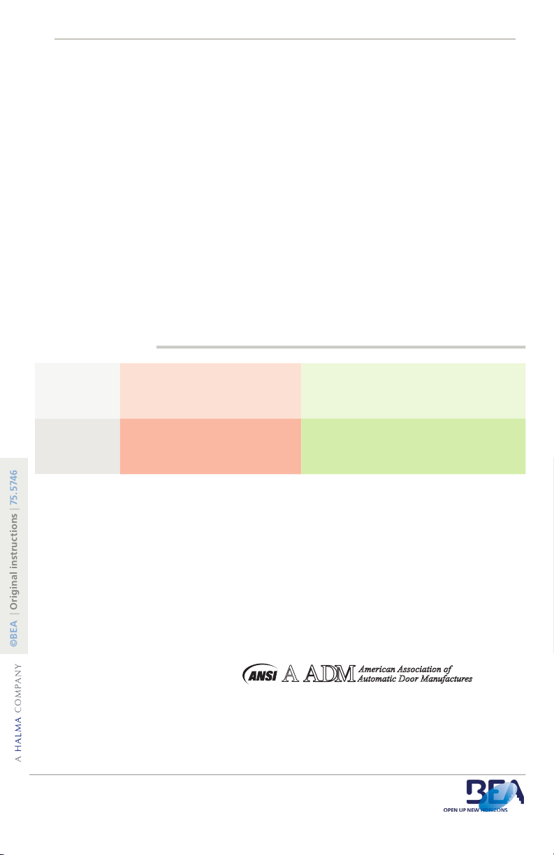
manuals.online logo
Brands
  1. Home
  2. •
  3. Brands
  4. •
  5. Halma
  6. •
  7. Accessories
  8. •
  9. Halma BEA MS09 User manual

Halma BEA MS09 User manual

MAGIC SWITCH: MS09
1
2
3
4
75.5746.04 MS-09 20151020 Page 1 of 4
Technology Microwave - Doppler Radar (24.125 GHz)
Detection Mode Motion (bidirectional)
Radiated Frequency 24.125 GHz
Radiated Power Density 5 mW/cm2
Supply Voltage 12 to 24VAC ± 10%
12 to 24VDC +30% / -10%
Current Consumption < 1.2W
Temperature Range -4°F to + 131°F ( -20°C to +55°C)
Enclosure Rating NEMA 4
Sensing Zone * 4 - 24 inches (adjustable)
Output
Relay contact rating (max voltage)
Relay contact rating (max current)
Max switching power
Relay with switch-over contact (voltage free)
60 VDC / 125 VAC
1 A (resistive)
30 W (DC) / 60 VA (AC)
Output Hold Time 0.5 s (in pulse mode)
Temperature Range -4°F to +131°F
Material ABS / PC
Certication
Electromagnetic compatibility (EMC) according to
2004/108/EC
FCC: G9B-MS08 / 2ABWS-10TD900PB
IC: 4680A-MS08 / 4680A-10TD900PB
* Use of the device outside the intended application cannot be guaranteed by the manufacturer.
TECHNICAL SPECIFICATIONS
DESCRIPTION
ENGLISH
NEMA 4 | Touchless | Activation Sensor
10MS09TL (shown) 10MS09L
Text & Logo Logo Only
Specifications are subject to change without prior notice.
1. faceplate
2. microwave motion sensor
3. connector
4. housing
* Sensing Zone is dependent upon
• Size (area) of object
• Orientation of object
• Speed of object
• Environmental conditions
Screw (x4)
1
2
PRECAUTIONS

Page 2 of 4 75.5746.04 MS-09 20151020
WIRING
Only trained and
qualified personnel
may install and setup
the sensor.
The warranty is invalid if
unauthorized repairs are
made or attempted by
unauthorized personnel.
Always test the proper
operation of the
installation before
leaving the premises.
The door control unit
and the door cover
profile must be correctly
grounded.
1INSTALLATION
APPLICATIONS
Swing Doors Sliding Doors
NOTE: Do not install the sensor within the swingpath of the door.
M
S
0
9
• PWR: Black - 12 to 24 VAC / VDC: -5% to +10%
• PWR: Red - 12 to 24 VAC / VDC: -5% to +10%
•NC: Yellow - NC Contact
• NO: Green - NO Contact
• COM: White - Common at Door Control
C
O
N
T
R
O
L
Black - 12 to 24 VAC / VDC
Red - 12 to 24 VAC / VDC
White - Com at Door Control
Green - NO Contact
Yellow - NC Contact
Connect the exiting 2 wires running through the wall (previously used for the activation relay of the
hardwired, mechanical pushplate) to the MS09 sensor’s PWR (black) and PWR (red) terminals. At
the door control, move the 2 wires from the activation circuit to power (see Technical Specications
for power information).
SENSOR
TIPS
Run conduit prior to
installing sensor
Fully adjust
sensor after entire
installation is
complete
Industrial Doors Cleanrooms
75.5746.04 MS-09 20151020 Page 3 of 4
3SETTINGS & ADJUSTMENTS
4”
24”
MS09 Sensing Filed
Potentiometer
Output Mode Switch

24”
4”
Toggle Mode
Pulse Mode
DETECTION ZONE - potentiometer
COUNTERCLOCKWISE - decrease (4’’ minimum)
CLOCKWISE - increase (24’’ maximum *)
OUTPUT MODE - slide switch
PULSE - switch down
TOGGLE - switch up
* Maximum Detection Zone will
vary depending on size (area),
orientation, and speed of object as
well as environmental conditions.
SENSOR FUNCTIONALITY
TIMED MODE - Recommended for automatic door applications. In Timed Mode, a detection
activates the relay and the relay holds for a predetermined amount of time adjusted by the Output
Time potentiometer (1 to 30 seconds, counterclockwise - decrease, clockwise -increase).
TOGGLE MODE - Recommended for switch applications. In Toggle Mode, a detection activates the
relay and a second detection deactivates the relay. The relay will hold indenitely until a second
detection occurs.
For the 900 MHz wireless programming instructions, please reference BEA User’s Guide 75.5786
which comes with the 900 MHz wireless receiver (sold separately).
WIRELESS FUNCTIONALITY
B C
Sensor does not
seem to detect
1. Bad or no power 1. Check power supply
2. Detection range too short 2. Adjust detection zone
3. Incorrect wiring 3. Check wiring
Sensor stays in
detection
1. Envionmental conditions 1. Remove moving objects from around sensor
2. Incorrect wiring 2. Check wiring (NO and NC)
3. Wrong output mode 3. Switch output mode to pulse
Page 4 of 4 75.5746.04 MS-09 20151020
©BEA | Original instructions | 75.5746
TROUBLESHOOTING
The complete declaration of conformity is available on our website: www.beasensors.com
Upon completion of the installation or service work, at a minimum, perform a daily safety check in accordance with the
minimum inspection guidelines provided by AAADM. Provide each equipment owner with an owner’s manual that
includes a daily safety checklist and contains, at a minimum, the information recommended by AAADM. Offer an
information session with the equipment owner explaining how to perform daily inspections and point out the location of
power/operation switches to disable the equipment if a compliance issue is noted. The equipment should be inspected
annually in accordance with the minimum inspection guidelines. A safety check that includes, at a minimum, the items
listed on the safety information label must be performed during each service call. If you are not an AAADM certified
inspector, BEA strongly recommends you have an AAADM certified inspector perform an AAADM inspection and place
a valid inspection sticker below the safety information label prior to putting the equipment into operation.
AAADM American Association of
Automatic Door Manufactures
ANSI / AAADM Compliance
24/7 Tech Support: 1-800-407-4545 | Customer Service: 1-800-523-2462 | General Tech Questions: T[email protected] | Tech Docs: www.beasensors.com
FCC
FCC: G9B-21019
This device complies with Part 15 of the FCC Rules. Operation is subject to the following two conditions: (1) this device
may not cause harmful interference, and (2) this device must accept any interference received, including interference that
may cause undesired operation.
Changes or modications not expressly approved by BEA Incorporated could void the user’s authority to operate the
equipment.
Note: This equipment has been tested and found to comply with the limits for a Class A digital device, pursuant to part
15 of the FCC Rules. These limits are designed to provide reasonable protection against harmful interference when the
equipment is operated in a commercial environment. This equipment generates, uses, and can radiate radio frequency
energy and, if not installed and used in accordance with the instruction manual, may cause harmful interference to radio
communications. Operation of this equipment in a residential area is likely to cause harmful interference in which case the
user will be required to correct the interference at his own expense.
This device complies with Industry Canada licence-exempt RSS standard(s). Operation is subject to the following two con-
ditions: (1) this device may not cause interference, and (2) this device must accept any interference, including interference
that may cause undesired operation of the device.
Le présent appareil est conforme aux CNR d’Industrie Canada applicables aux appareils radio exempts de licence. L’ex-
ploitation est autorisée aux deux conditions suivantes : (1) l’appareil ne doit pas produire de brouillage, et (2) l’utilisateur
de l’appareil doit accepter tout brouillage radioélectrique subi, même si le brouillage est susceptible d’en compromettre le
fonctionnement.

This manual suits for next models

2

Other Halma Accessories manuals

Halma BEA LZR-WIDESCAN Operating instructions

Halma

Halma BEA LZR-WIDESCAN Operating instructions

Halma LZR-WIDESCAN User manual

Halma

Halma LZR-WIDESCAN User manual

Halma SENSITRON SMART3 NC User manual

Halma

Halma SENSITRON SMART3 NC User manual

Halma BEA MAGIC SWITCH CHROMA User manual

Halma

Halma BEA MAGIC SWITCH CHROMA User manual

Halma BEA LZR-WIDESCAN User manual

Halma

Halma BEA LZR-WIDESCAN User manual

Halma BEA SEAGLE TWO User manual

Halma

Halma BEA SEAGLE TWO User manual

Halma LZR-WIDESCAN User manual

Halma

Halma LZR-WIDESCAN User manual

Halma BEA ULTIMO User manual

Halma

Halma BEA ULTIMO User manual

Halma BEA FALCON-L User manual

Halma

Halma BEA FALCON-L User manual

Halma BEA BODYGUARD III-C User manual

Halma

Halma BEA BODYGUARD III-C User manual

Halma BEA IS40P User manual

Halma

Halma BEA IS40P User manual

Halma BEA DK-12 User manual

Halma

Halma BEA DK-12 User manual

Popular Accessories manuals by other brands

PCB Piezotronics 208C05 Installation and operating manual

PCB Piezotronics

PCB Piezotronics 208C05 Installation and operating manual

sun control Catalina Use and maintenance

sun control

sun control Catalina Use and maintenance

Seametrics LevelSCOUT instructions

Seametrics

Seametrics LevelSCOUT instructions

Orbegozo DOB 3000 instruction manual

Orbegozo

Orbegozo DOB 3000 instruction manual

E+E Elektronik EE600 user manual

E+E Elektronik

E+E Elektronik EE600 user manual

Hama LP-7 instructions

Hama

Hama LP-7 instructions

Hytronik HC038V manual

Hytronik

Hytronik HC038V manual

Work Sharp PRECISION ADJUST instructions

Work Sharp

Work Sharp PRECISION ADJUST instructions

VDO SENSORS -  FOR ENGINE MANAGEMENT V3.0 brochure

VDO

VDO SENSORS - FOR ENGINE MANAGEMENT V3.0 brochure

Safety Technology International STI-3350 quick start guide

Safety Technology International

Safety Technology International STI-3350 quick start guide

SICK safeVisionary2 operating instructions

SICK

SICK safeVisionary2 operating instructions

Termozeta TZR60 instruction manual

Termozeta

Termozeta TZR60 instruction manual

Pyxis ST-765SS Series user manual

Pyxis

Pyxis ST-765SS Series user manual

NuTone PORTABLE PILOT LA553WH Installation & operating instructions

NuTone

NuTone PORTABLE PILOT LA553WH Installation & operating instructions

Vega VEGAPULS Air 23 operating instructions

Vega

Vega VEGAPULS Air 23 operating instructions

iDo Seven D manual

iDo

iDo Seven D manual

NATURE & DECOUVERTES 15211980 manual

NATURE & DECOUVERTES

NATURE & DECOUVERTES 15211980 manual

Goldair GEFT215C operating instructions

Goldair

Goldair GEFT215C operating instructions

manuals.online logo
manuals.online logoBrands
  • About & Mission
  • Contact us
  • Privacy Policy
  • Terms and Conditions

Copyright 2025 Manuals.Online. All Rights Reserved.