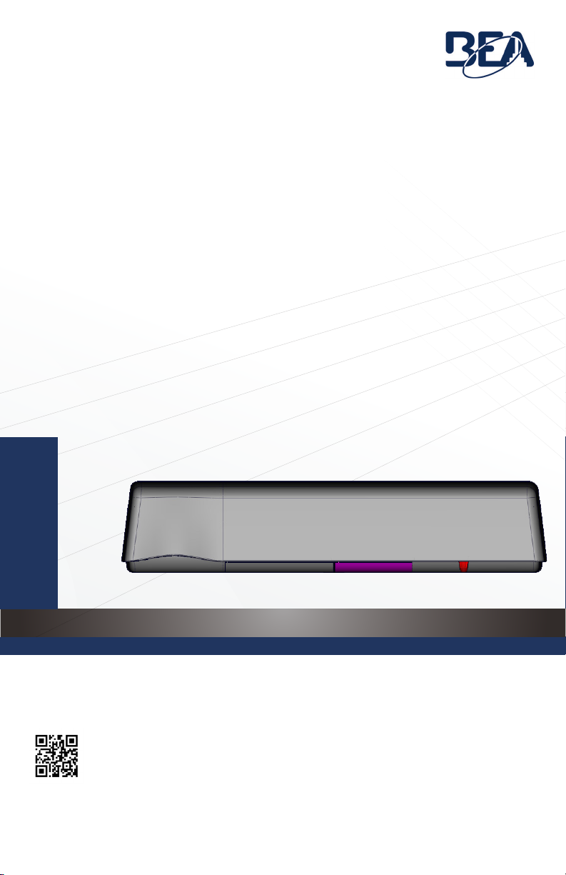
3
C3
C3
C2
C2
C1
C1
75.0034.02 ULTIMO 20211013 Page 9 of 16
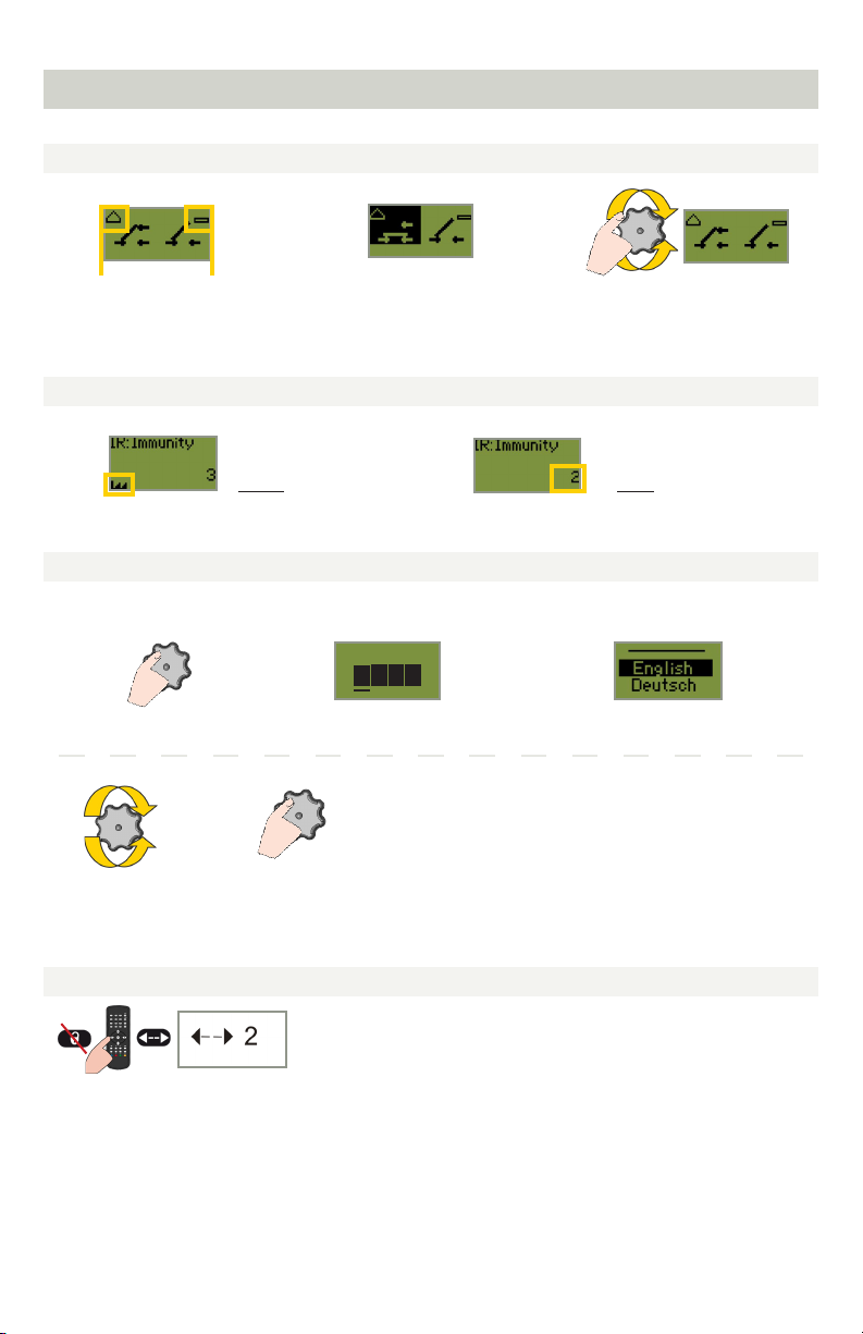
THRESHOLD SETTINGS
a dotted line indicates that
the given curtain is active
at full open, and inactive
during door closing cycle
(settings 2 and 5)
a solid line indicates that
the given curtain is active
at full open and partially
active during door closing
cycle (settings 1 and 4)
NON-THRESHOLD SETTINGS
a solid line indicates that
the given curtain is always
active (settings 3, 6, and 7)
* When IR:Curtains is set to 0, the AIR will not trigger the output for a period of 5 minutes.
After 5 minutes expires, IR:Curtains will revert back to the previously chosen setting.
GENERAL
the number of squares on
a line indicates the curtain
number (i.e. C1, C2, or C3)
the rectangles on each
side of the setting number
represent sliding door
panels
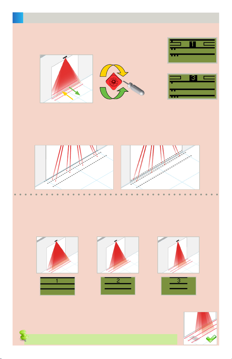
ACTIVE INFRARED SAFETY FIELD
NUMBER OF CURTAINS / POSITION OF CURTAINS
(IR:CURTAINS, MENU 1)
Choose the number and position of the AIR curtains based on your application.
The sensor is defaulted to Non-Threshold setting (3). If threshold is desired, you may choose
Threshold setting 1, 2, 4, or 5; be sure that the curtain placement matches the LCD screen.
If necessary, use visible spots and red adjustment knob to position properly (see page 10).
UNDERSTANDING THE LCD "CURTAINS" GRAPHICS
1. Activate the four visible spots (press gray knob twice) to verify the
position of the AIR curtains.
Visibility depends on external conditions. When spots are not
visible, use the Spotfinder to locate the curtains.
ANGLE
THRESHOLD NON-THRESHOLD
0 1 2 3 (default)
4 5 6 7
double
press
OR