manuals.online logo
Brands
  1. Home
  2. •
  3. Brands
  4. •
  5. Halma
  6. •
  7. Security Sensor
  8. •
  9. Halma Apollo Marine 65 Series User manual

Halma Apollo Marine 65 Series User manual

MANAGEMENT
SYSTEMS
Assessed to ISO 9001:2008
Cert/LPCB ref. 010
Assessed to ISO 14001:2004
Cert/LPCB ref. 010 EMS
MANAGEMENT
SYSTEMS
Cert/LPCB ref. 010
PRODUCT
CERTIFICATION
36 Brookside Road, Havant
Hampshire, PO9 1JR, UK.
Tel: +44 (0)23 9249 2412
Fax: +44 (0)23 9249 2754
Email: sales@apollo-fire.com
Web: www.apollo-fire.co.uk
Series 65
Marine Base Mounted UV Flame Detector
Product overview
Product Marine Base Mounted UV Flame
Detector
Part No. 55000-026MAR
PP5071/2017/Issue 1
Page 1 of 2
© Apollo Fire Detectors Limited 2017
Technical Data
All data is supplied subject to change without notice. Specifications are
typical at 24 V, 25°C and 50% RH unless otherwise stated.
Supply voltage 17 - 28 V dc
Quiescent current 550 µA
Alarm voltage 6 to 33 V dc
Alarm current 61 mA at 28 V
54 mA at 24 V
20 mA at 10 V
Terminal functions L1 in and out
L2
-R
Supply positive
Supply negative
Remote indicator
negative
connection
Remote output characteristics Remote is a current sink to the negative
line limited to 17 mA
Alarm indicator Red light emitting diode (LED)
Design alarm load 420 Ω in series with a 2 V drop
Holding voltage 6 V min
Holding current 10 mA min
Minimum voltage required to
illuminate indicators
12 V
Alarm reset voltage < 1 V
Alarm reset time 1 second
Range of view 0.1 m² n-heptane at 25 m
Sensitivity Class 1, EN 54-10
Field of view 90º cone
Spectral response UV 180 to 260 nm
Operating temperature
(no condensing or icing)
-40ºC to +70ºC
Storage temperature -40ºC to +85ºC
Relative humidity 95% non-condensing
IP rating IP66
Standards and approvals MED, ABS and CCS
Dimensions 100 mm x 40 mm detector only
100 mm x 48 mm detector and base
Weight 150 g - detector only
210 g - detector and base
Materials: Housing White flame-retardant polycarbonate
Sensing window 2 mm Quartz
Terminals Nickel plated stainless steel
The Series 65 Marine Base Mounted Ultraviolet (UV) Flame
Detector is designed to protect indoor areas where open fires may
be expected.
UV flame detectors are designed for use in enclosed spaces and
require a clear line of sight within the area to be protected. They
are unaected by draughts or convection currents.
They are fast acting and respond to a flame more than 25 m away.
Operation
The Series 65 Marine Base Mounted UV Flame Detector is
sensitive to UV radiation emitted by flames during combustion.
Since it requires only UV radiation the detector responds even to
stationary flames with no flicker such as cigarette lighters and
blue gas flames.
The detector is set to respond to UV radiation (180 - 260 nm)
emitted by almost all flames including those invisible to the naked
eye, e.g. hydrogen fires.
The detector has a single UV sensor with a narrow spectral
response in order to discriminate between flames and most
spurious sources of radiation and is designed for use in internal
fully enclosed areas.
CAUTION: The detector will also detect electrical
discharges from lightning or arc welding.
Product information
Approvals
Electrical description
The detector signals an alarm state by switching an alarm latch
on increasing the current drawn from the supply from 550 µA to a
maximum of about 75 mA. This fall in impedance of the detector is
recognised by the control panel as an alarm signal.
The alarm current also illuminates the detectors integral LEDs. A
remote indicator connected between the L1 In terminal and the -R
terminal will have a voltage equal to the supply voltage less one
volt across it and so will illuminate.
To ensure correct operation of the detector the control panel must
be arranged to supply a maximum of 28 V dc and a minimum of
12 V dc in normal operation.
The supply may fall to 6 V dc in alarm conditions if a supply current
of at least 10 mA is available at this voltage.
To ensure eective illumination of the integral LEDs and any
remote indicator, the supply to the detector should exceed 12 V.
To restore the detector to a quiescent condition, ensuring all
flames are extinguished , interrupt the supply to the detector for a
minimum of one second.
Note: When using the detector avoid; locating in an area with an
outside view, UV lamps, electrical sparking, welding and sources of
radiation, UV light sources, prolonged ambient temperatures above
60ºC and any obstruction to the field of view.
Installation
If fitting to an XP95 Zone Monitor do not fit more than one device
per zone.
If fitting to a conventional control panel, please verify the quantity
that can be fitted per zone with the panel manufacturer.
The field of view of the flame detector is shown in Figure 1, which
also gives information on the size of fire that is detectable at
various distances.
The flame detectors can also be ceiling mounted, positioned above
the anticipated flame source or at the centre of the area to be
protected, perpendicular to the floor below. If the detector cannot
see the whole of the area to be protected, one or more additional
detectors may be required. Refer to Figure 2 to establish the
detector performance. The area of detection is dependent on the
detectors height above the likely source of flame. The detector
has a 90º conical field of view or 45º either side of the viewing
axis centre. The maximum ceiling height is 20 m. If the detector is
perpendicular to the floor and at a height of 10 m then the detector
will view a circular floor area below with a 10 m radius - 20 m
diameter circle.
Figure 1: Field of view - wall mount
–90°
–75°
–60°
–45°
–30°
–15° 0° 15°
30°
45°
60°
75°
90°
0.1m² flame seen
at 25m in straight line
from flame detector
0.4m² flame seen
at 40m in straight line
from flame detector
0.1m² flame not seen
at 25m since it is not
in the field of view of
the flame detector
25m m040
centre line of detector detection of 0.4m² flame
detection of 0.1m² flame
Figure 2: Field of view - ceiling mount
Vertical Plane Ceiling
5m
10m
15m
20m
Floor
Plan View
10m Dia.
20m Dia.
30m Dia.
40m Dia.
Height
© Apollo Fire Detectors Limited 2009/TP
Marine Equipment Directive 2014/90/EU
The Series 65 Marine Base Mounted Flame Detector complies
with the essential requirements of the Marine Equipment Directive
2014/90/EU.
PP5071/2017/Issue 1
Page 2 of 2

Other Halma Security Sensor manuals

Halma apollo REACH User manual

Halma

Halma apollo REACH User manual

Halma BEA IXIO-DO1 I User manual

Halma

Halma BEA IXIO-DO1 I User manual

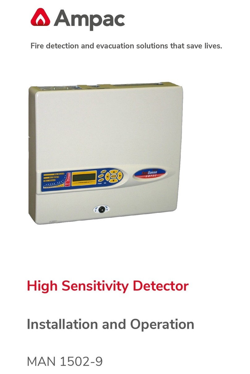
Halma Ampac FastSense PLUS Guide

Halma

Halma Ampac FastSense PLUS Guide

Halma Apollo XP95 I.S. User manual

Halma

Halma Apollo XP95 I.S. User manual

Halma BEA G3 User manual

Halma

Halma BEA G3 User manual

Halma SENSITRON SMART3G-GrI User manual

Halma

Halma SENSITRON SMART3G-GrI User manual

Halma BEA ACTIV8 THREE ON User manual

Halma

Halma BEA ACTIV8 THREE ON User manual

Halma SENSITRON SMART3H-FM LITE User manual

Halma

Halma SENSITRON SMART3H-FM LITE User manual

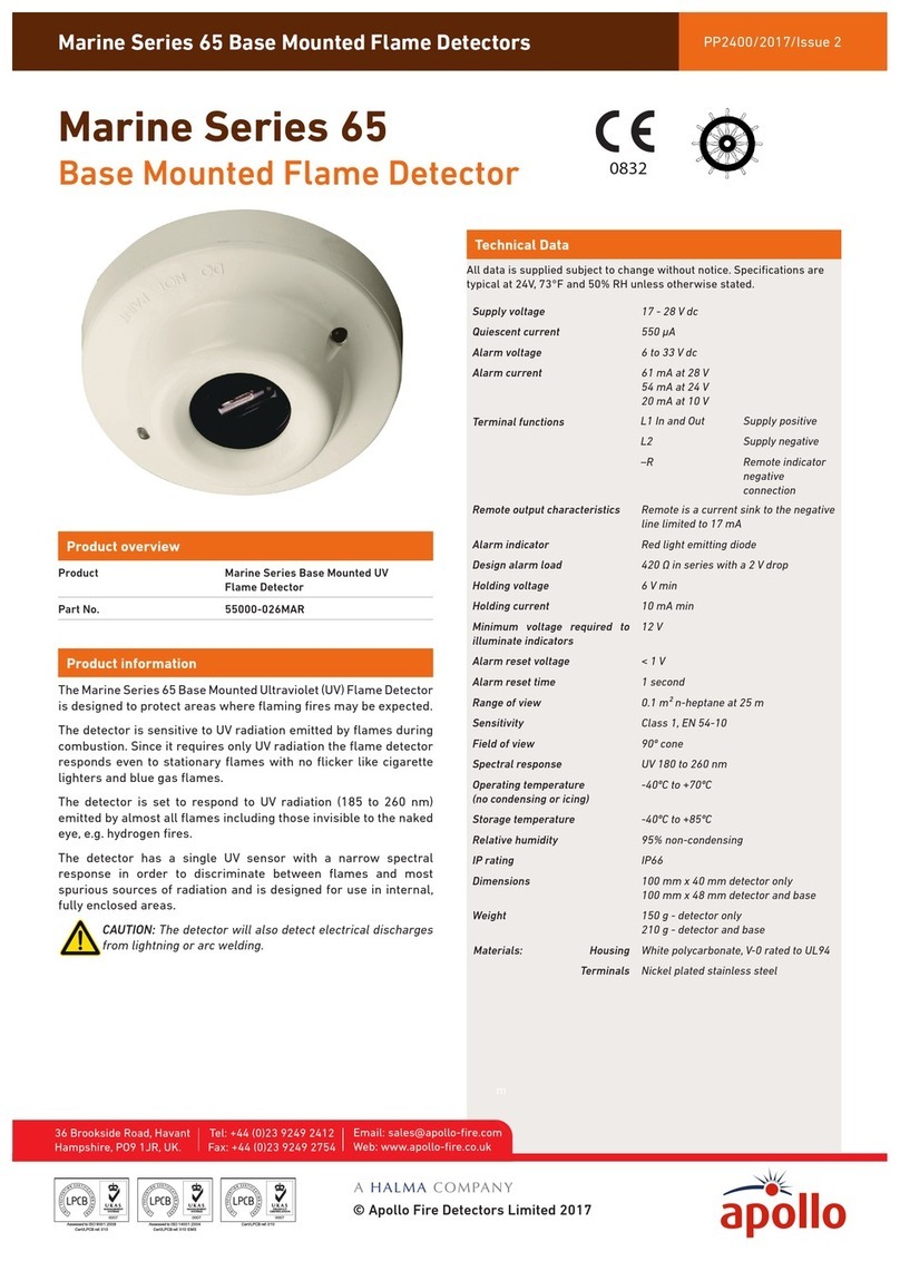
Halma Apollo Marine 65 Series User manual

Halma

Halma Apollo Marine 65 Series User manual

Halma Ampac FastSense 25 Guide

Halma

Halma Ampac FastSense 25 Guide

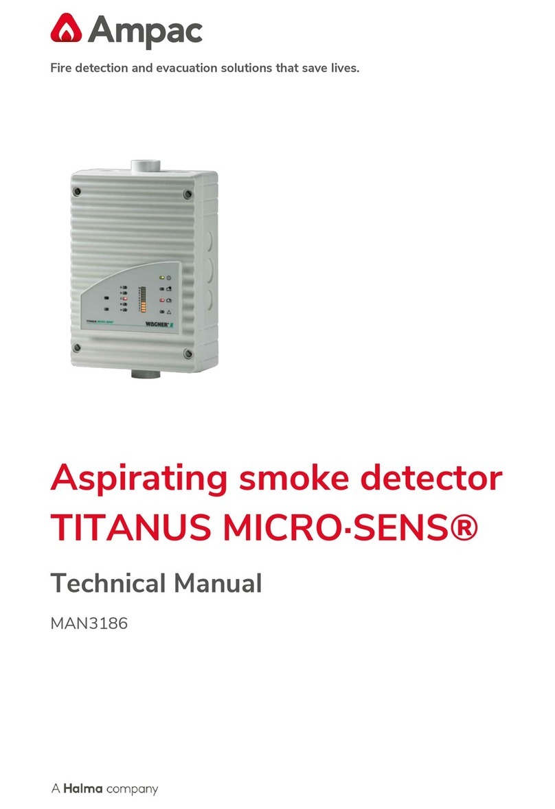
Halma Ampac TITANUS MICRO-SENS User manual

Halma

Halma Ampac TITANUS MICRO-SENS User manual

Halma BEA IXIO Series User manual

Halma

Halma BEA IXIO Series User manual

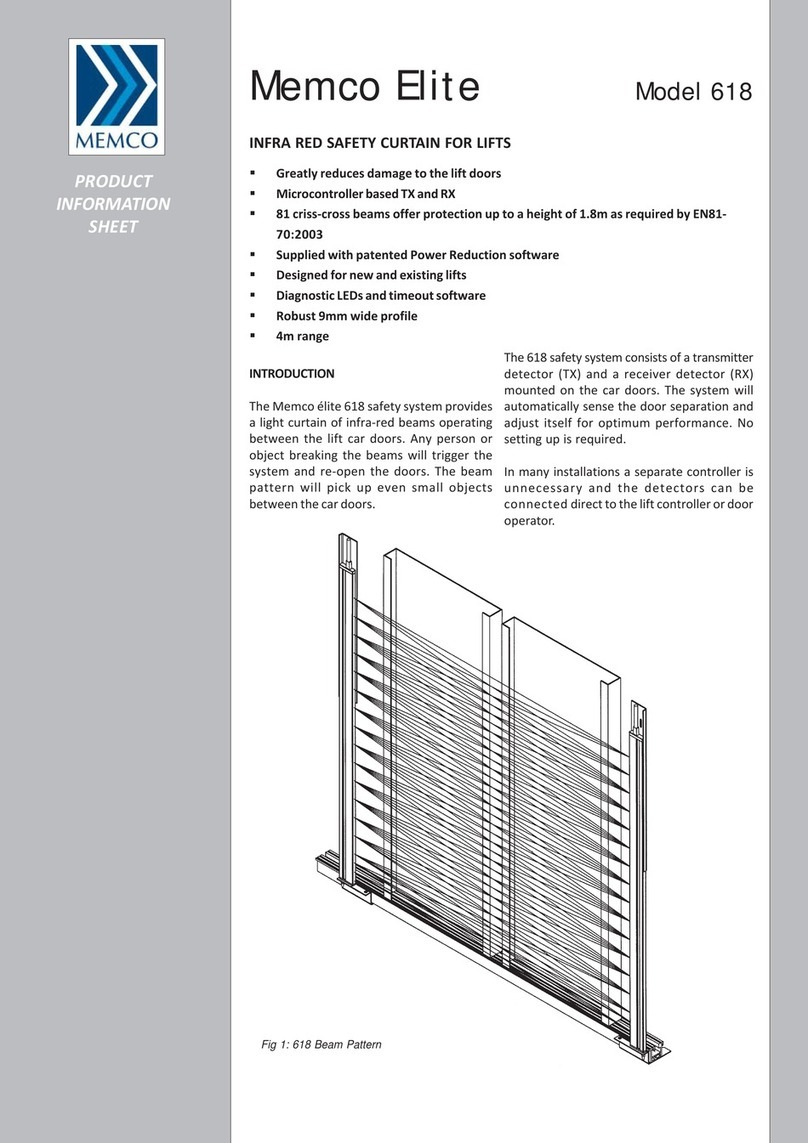
Halma MEMCO Elite 618 User manual

Halma

Halma MEMCO Elite 618 User manual

Halma BEA IXIO Series User manual

Halma

Halma BEA IXIO Series User manual

Popular Security Sensor manuals by other brands

RLE Technologies Falcon quick start guide

RLE Technologies

RLE Technologies Falcon quick start guide

General Photonics BPD-002-OEM-400-15 Instructions Note

General Photonics

General Photonics BPD-002-OEM-400-15 Instructions Note

hyfire HFI-DPT-05 instruction manual

hyfire

hyfire HFI-DPT-05 instruction manual

Trebs KC-186 Operation manual

Trebs

Trebs KC-186 Operation manual

Busch-Jaeger Busch-Watchdog 280 ProfessionalLINE installation instructions

Busch-Jaeger

Busch-Jaeger Busch-Watchdog 280 ProfessionalLINE installation instructions

SWARCO IG325/2 user manual

SWARCO

SWARCO IG325/2 user manual

Ansell VIKING PROTECH II owner's manual

Ansell

Ansell VIKING PROTECH II owner's manual

Argus Security TAURUS TW-DO-01 quick start guide

Argus Security

Argus Security TAURUS TW-DO-01 quick start guide

hager EE880 manual

hager

hager EE880 manual

GJD D-TECT 3 IP GJD260 manual

GJD

GJD D-TECT 3 IP GJD260 manual

PCB Piezotronics PCB-234B Installation and operating manual

PCB Piezotronics

PCB Piezotronics PCB-234B Installation and operating manual

Ampcontrol GASGUARD 65-6550 Series user manual

Ampcontrol

Ampcontrol GASGUARD 65-6550 Series user manual

Lambrecht aem 8141.6 user manual

Lambrecht

Lambrecht aem 8141.6 user manual

Renkforce 1362922 operating instructions

Renkforce

Renkforce 1362922 operating instructions

GST DI-9104Exd quick start guide

GST

GST DI-9104Exd quick start guide

Desco 73880 TECNICAL BULLETIN

Desco

Desco 73880 TECNICAL BULLETIN

Wintop iDoorSensor quick start

Wintop

Wintop iDoorSensor quick start

Arcom QAM Snare Snoop user manual

Arcom

Arcom QAM Snare Snoop user manual

manuals.online logo
manuals.online logoBrands
  • About & Mission
  • Contact us
  • Privacy Policy
  • Terms and Conditions

Copyright 2025 Manuals.Online. All Rights Reserved.