manuals.online logo
Brands
  1. Home
  2. •
  3. Brands
  4. •
  5. Halsey Taylor
  6. •
  7. Plumbing Product
  8. •
  9. Halsey Taylor 96852CA User manual

Halsey Taylor 96852CA User manual

Page 1 97631C (REV. D - 06/17)
Warning
To avoid risk of electrical shock, personal injury or death, disconnect from electrical power supply and shutoff water
supply before installing this plumbing kit.
Caution
To avoid property damage, personal injury and voiding your warranty:
• Have this kit installed by an authorized person. (Installation person should be familiar with water cooler plumbing,
refrigeration systems and general plumbing practices.)
• Install this kit into one of the Halsey Taylor models listed above.
• Make sure you read, understand and follow the instructions.
• Wear hand and arm protection. Use caution when working inside the water cooler. Edges inside the water cooler
can be sharp.
• Wear eye safety goggles.
Required Tools
To install this kit the following tools are required:
• Phillips Screwdriver
• Needle Nose Pliers
• 1/4” and 5/16” Nut or Socket Driver
• Tubing Cutter (Mini)
• 11/16” (.687”) diameter hole punch or drill bit.
• Large adjustable wrench.
Operation of Quick Connect Water Fittings:
Cooler is provided with lead-free connectors which utilize an
“O”-ring water seal. To remove tubing from the tting, relieve
water pressure, push in on the darker gray collar before
pulling on the tubing. To insert tubing, push tube straight
into tting until it reaches a positive stop, approximately
3/4” (19mm). Deburr cut tube ends before inserting into the
Quick Connect Fitting. Burrs on the tube end will cut the
internal “O”-Ring and will allow the tting to leak.
OPERATION OF QUICK CONNECT FITTINGS
TUBE IS
SECURED
IN POSITION
SIMPLY PUSH IN
TUBE TO ATTACH
PUSH IN COLLET
TO RELEASE TUBE
PUSHING TUBE IN BEFORE
PULLING IT OUT HELPS TO
RELEASE TUBE
Parts List
Refer to the illustration to make sure you receive all plumbing kit parts. If any parts are missing contact your
Halsey Taylor distributor. Depending on model, not all parts are required.
7
234
6
5
PART NO. DESCRIPTION
56092C
15009C
70683C
70682C
70817C
100322740560
75630C
Poly Tubing
Glass Filler Nipple
Connector 1/4" Tubing
Tee 1/4" Tubing
Elbow 1/4"
Gasket (4)
Glass Filler
1
2
3
4
5
6
7
ITEM
NO.
1
NOTE: Replacement plumbing hardware components may be ordered as a kit: 1000002033 Glass Filler Hardware
and Waterway.
Glass Filler Plumbing Kit
Part Number 96852CA
This plumbing kit is designed to be used with Halsey Taylor
HTVZ, HAC, S-Series, SCWT, SW and WM Models manufactured after December 1998.
Page 297631C (REV. D - 06/17)
STEP 1
Remove Cooler Basin
• Remove lower front panel.
• Disconnect cooler from electrical supply.
• Turn off water supply to unit.
• Remove basin screws (A) (4 each side, 8
total).
• If cooler is installed remove strainer and drain
plug (B) or disconnect unit from trap.
• Lift up basin, remove tubing from bubbler nut (C).
• Remove upper front panel (D) to hold bubbler
tting from turning.
• Remove cooler basin.
STEP 2
• Drill or punch an 11/16” (.687”) diameter hole in
the cooler basin per dimensions shown
HAC Model
Overview
The following illustration shows the tube routing before and after the installation of the Glass Filler Kit.
Before (Non-Pressurized Tank) After (Pressurized Tank)
The water storage tank must be converted to a pressurized tank for the glass ller to operate properly. The tank
is non-pressurized in a standard unit. The following steps detail how the water ow tubing is re-routed to create a
pressurized tank and provide a supply line to the glass ller.
AD
B
Note: Item numbers in the following steps refer to items in Parts List on page 1.
Step 1 & 2
2.38"
7.00”
C
Page 3 97631C (REV. D - 06/17)
STEP 3
Cut and Remove Internal Plumbing
• Remove tank to bubbler tube (A).
• Disconnect bubbler tube at chilled tank water outlet.
• Save the tube and bubbler tting. These will be used in step 4.
• Cut supply tubes at locations (B) and (C).
• Remove and discard bent tubes from water regulator (D).
• Refer to details “Operation of Quick Connect Fittings” for removing tubes.
STEP 4
Reconnect Internal Plumbing
• Connect water inlet line to chiller inlet.
• Using (Item 3) reconnect tubes cut at (B) and (C)
in step 3.
• Connect chiller outlet to tee.
• Cut a 12 inch long piece of (Item 1).
Install into the chiller water outlet. Connect end
to tee (Item 4).
• Connect tee to regulator and glass ller supply tube.
• Cut a 6 inch long piece of (Item 1).
• Connect one end of tube to tee (Item 4) and
other end to water regulator inlet (A).
• Cut a 12 inch long piece of (Item 1).
• Connect to tee (Item 4) and to Glass Filler Nipple
(Item 2)
• Connect bubbler tube to regulator.
• Use tank to bubbler tube, removed in Step 3, cut length of tube to 10 inches and connect to regulator
outlet.
Item 3
A
B
D
C
STEP 5
Reassemble Unit
• Connect Bubbler and Glass Filler.
• Using one gasket below the basin and one gasket
above the basin assemble the bubbler and glass
ller (Item 6) to the basin.
• Reassemble the unit and leak check.
• Assemble basin to the unit. Reattach with screws
removed in Step 1.
• Reassemble drain components.
• Turn on water supply. Run water through bubbler
and glass ller. Check all connections for water
leaks.
• Reconnect electrical supply.
• Replace panels.
Item 4
Item 2
Bubbler Tube
Step 3(A) Step 3(B)
Step 4
Step 5
A
Page 497631C (REV. D - 06/17)
Overview
The following illustration shows the tube routing before and after the installation of the Glass Filler Kit.
Before (Non-Pressurized Tank) After (Pressurized Tank)
The water storage tank must be converted to a pressurized tank for the glass ller to operate properly. The
tank is non-pressurized in a standard unit. The following steps detail how the water ow tubing is re-routed to
create a pressurized tank and provide a supply line to the glass ller.
A
Note: Item numbers in the following steps refer to items in Parts List on page 1.
Step 1 & 2
SCWT Model
STEP 1
Remove Cooler Front Panel
• Remove front panel.
• Remove screws on kick plate and front panel (A).
• Remove front panel.
• Disconnect cooler from electrical supply.
• Turn off water supply to unit.
• Remove bubbler (B).
• Remove pushbutton (C).
• If cooler is installed, remove strainer and drain plug (D)
or disconnect unit from trap.
• Remove 4 screws and take off basin.
STEP 2
• Drill or punch an 11/16” (.687”) diameter hole in the center of
the raised circular pad at the right rear corner of the basin.
C
B
D
Page 5 97631C (REV. D - 06/17)
STEP 3
Cut and Remove Internal Plumbing
• Remove tank to bubbler tube (A).
• Disconnect bubbler tube at chilled tank water outlet.
• Cut supply tubes at locations (B) and (C).
• Remove and discard bent tubes from water regulator (D).
• Refer to details “Operation of Quick Connect Fittings” for removing tubes.
STEP 4
Reconnect Internal Plumbing
• Connect water inlet line to chiller inlet.
• Using (Item 3) reconnect tubes cut at (B) and (C)
in step 3.
• Connect chiller outlet to tee.
• Cut a 8 inch long piece of (Item 1).
Install into the chiller water outlet. Connect end
to tee (Item 4).
• Connect tee to regulator and glass ller supply tube.
• Cut a 6 inch long piece of (Item 1).
• Connect one end of tube to tee (Item 4) and
other end to water regulator inlet (A).
• Cut a 12 inch long piece of (Item 1).
• Connect to tee (Item 4) and to Glass Filler Nipple
(Item 2), not shown.
• Connect bubbler tube to regulator.
• Use tank to bubbler tube, removed in Step 3, cut length of tube to 10 inches and connect to regulator outlet.
A
B
D
C
STEP 5
Reassemble Unit
• Connect Bubbler and Glass Filler.
• Using one gasket below the basin and one gasket
above the basin assemble the bubbler and glass
ller (Item 6) to the basin.
• Reassemble the unit and leak check.
• Turn on water supply. Run water through bubbler
and glass ller. Check all connections for water
leaks.
• Reconnect electrical supply.
• Replace front panel.
A
Item 4
Bubbler Tube
Step 3(A) Step 3(B)
Step 4
Step 5
Item 3
Page 697631C (REV. D - 06/17)
Overview
The following illustration shows the tube routing before and after the installation of the Glass Filler Kit.
The water storage tank must be converted to a pressurized tank for the glass ller to operate properly. The tank
is non-pressurized in a standard unit. The following steps detail how the water ow tubing is re-routed to create
a pressurized tank and provide a supply line to the glass ller.
Note: Item numbers in the following steps refer to items in Parts List on page 1.
SW/WM Model
STEP 1
Remove Cooler Front Panel
• Remove front panel.
• Remove screws on under side of front panel. (A)
• Remove front panel.
• Disconnect cooler from electrical supply.
• Turn off water supply to unit.
• Remove bubbler. (B)
• Remove pushbutton. (C)
• If cooler is installed, remove strainer and drain plug (D)
or disconnect unit from trap.
• Remove 4 screws and take off basin.
STEP 2
• Drill or punch an 11/16” (.687”) diameter hole in the center of
the raised circular pad at the right rear corner of the basin.
Before (Non-Pressurized Tank) After (Pressurized Tank)
A
C
B
D
Step 1 & 2
Page 7 97631C (REV. D - 06/17)
STEP 4
Reconnect Internal Plumbing
• Connect water inlet line to chiller inlet.
• Using (Item 3) reconnect tubes cut at (B) and (C)
in step 3.
• Connect chiller outlet to tee.
• Cut a 8 inch long piece of (Item 1).
Install into the chiller water outlet. Connect end
to tee (Item 4).
• Connect tee to regulator and glass ller supply tube.
• Cut a 12 inch long piece of (Item 1).
• Connect one end of tube to tee (Item 4) and
other end to water regulator inlet (A).
• Cut a 12 inch long piece of (Item 1).
• Connect to tee (Item 4) and to Glass Filler Nipple
(Item 2), not shown.
• Connect bubbler tube to regulator
• Use tank to bubbler tube, removed in Step 3, cut length of tube to 10 inches and connect to regulator
outlet.
STEP 3
Cut and Remove Internal Plumbing
• Remove tank to bubbler tube (A).
• Disconnect bubbler tube at chilled tank water outlet.
• Cut supply tubes at locations (B) and (C).
• Remove and discard bent tubes from water regulator (D).
• Refer to details “Operation of Quick Connect Fittings” for removing tubes.
A
B D
C
STEP 5
Reassemble Unit
• Connect Bubbler and Glass Filler.
• Using one gasket below the basin and one gasket
above the basin assemble the bubbler and glass
ller (Item 6) to the basin.
• Reassemble the unit and leak check.
• Turn on water supply. Run water through bubbler
and glass ller. Check all connections for water leaks.
• Reconnect electrical supply.
• Replace front panel.
A
Item 4
Bubbler Tube
Step 3(A) Step 3(B)
Step 4
Step 5
Item 3
Page 897631C (REV. D - 06/17)
S-Series Model
Overview
This illustration shows the tube routing before and after the installation of the Glass Filler Kit.
Before After
Note: Item numbers in the following steps refer to items in Parts List on page 1.
STEP 1
• Remove front panel.
• Disconnect cooler from electrical supply.
• Turn off water supply to unit.
STEP 2
• Drill or punch an 11/16” (.687”) diameter hole in the location
shown at the right rear corner of the basin. If basin needs to be
removed, disconnect tube from bubbler, refer to detail on page 1
of operation of quick connect ttings.
Remove pushbutton/regulator assy. (A) by removing chrome
cover nut and pushbutton cap then large chrome hex nut. If
cooler is installed, remove trap from drain tube.
Remove 4 screws (B) and take off basin. Step 1 & 2
The water storage tank must be converted to a pressurized tank for the glass ller to operate properly. The
tank is non-pressurized in a standard unit. The following steps detail how the water ow tubing is re-routed to
create a pressurized tank and provide a supply line to the glass ller.
A
1.61”
1.81”
B
Page 9 97631C (REV. D - 06/17)
STEP 3
Cut and Re-Route Internal Plumbing
• Remove both tubes from regulator. (A)
• Remove tank to bubbler tube (B) at
the bubbler.
• Cut this tube 6” from the free end and
insert this 6” piece in the regulator inlet
port.
• Connect this 6” piece of tube to the
remaining part of the tube using the tee
(Item 4).
• Connect the branch of the tee to the
glass ller nipple (Item 2)
• Connect water inlet strainer to the
copper tube connected to the chiller inlet.
This is now the water inlet line.
• Connect bubbler to regulator using a
piece of polytube (Item 1).
STEP 4
Reassemble Unit
• Connect Glass Filler.
• Using one gasket below the basin and one gasket
above the basin assemble the bubbler and glass
ller (Item 6) to the basin.
• Reassemble the unit and leak check.
• Turn on water supply. Run water through bubbler
and glass ller. Check all connections for water leaks.
• Reconnect electrical supply.
• Replace front panel.
A
Item 4
B
Step 3
Item 2
Item 1
Step 4
Page 1097631C (REV. D - 06/17)
Step 1
Lower Cover Removal
• To access the refrigeration system and plumbing
connections, remove the four screws (E) to
remove lower cover (F).
• Disconnect unit from electrical supply.
• Turn off water supply to unit.
E
F
HTVZ Model
Overview
The following illustration shows the tube routing before and after the installation of the Glass Filler Kit.
The water storage tank must be converted to a pressurized tank for the glass ller to operate properly. The tank
is non-pressurized in a standard unit. The following steps detail how the water ow tubing is re-routed to create
a pressurized tank and provide a supply line to the glass ller.
Note: Item numbers in the following steps refer to items in Parts List on page 1.
Before (Non-Pressurized Tank) After (Pressurized Tank)
Step 1
Page 11 97631C (REV. D - 06/17)
STEP 3
Reconnect Internal Plumbing
• Connect water inlet line to chiller inlet.
• Connect chiller outlet to tee (Item 4).
• Cut a 12 inch long piece of tube (Item 1).
Install into the chiller water outlet. Connect end
to tee (Item 4).
• Connect tee to regulator and glass ller supply tube.
• Cut a 6 inch long piece of tube (Item 1).
• Connect one end of tube to tee (Item 4) and
other end to water regulator inlet (D).
• Cut another 12 inch long piece of tube (Item 1).
• Connect tube to tee (Item 4) and to Glass Filler
Nipple (Item 2).
• Connect bubbler tube to regulator.
• Use tank to bubbler tube, removed in Step 2, cut
length of tube to 10 inches and connect to
regulator outlet.
SCREWS
STEP 4
Reassemble Unit
• Using one gasket (Item 5) below the basin and
one gasket (Item 5) above the basin assemble
the glass ller (Item 6, not supplied) to the basin
with glass ller nipple (Item 2).
• Connect bubbler tube to glass ller nipple in basin.
• Flush components and leak check.
• Assemble basin to the unit. Reattach with screws
removed in Step 2.
• Turn on water supply and reconnect electrical supply.
Run water through the bubbler by depressing pushbar
and through glass ller. Check all connections for leaks.
Reinstall lower panel with screws removed in step 1.
3.75
3.75
Step 2
Step 3
STEP 2
Remove Cooler Basin
• Remove basin screws (2 each side, 4 total).
• If cooler is installed remove strainer and drain plug or disconnect unit from trap.
• Lift front of basin and disconnect bubbler tube from bubbler. Refer to details "Operation of Quick Connect Fittings" for
removing tubes.
• Remove cooler basin.
Remove glass ller plug from basin
If the hole HAS NOT been prepunched, then drill or punch a 11/16” (.687”) diameter hole in the cooler basin
where shown or desired. Note: Tube length may vary depending upon glass ller location.
Cut and Remove Internal Plumbing
• Disconnect bubbler tube (A) at chilled tank water outlet.Save the tube. This will be used in step 4.
• Disconnect supply tubes at locations (B) and (C).
• Remove and discard bent tubes from water regulator (D).
• Refer to details “Operation of Quick Connect Fittings” for removing tubes.
Step 4
Page 1297631C (REV. D - 06/17)
FOR PARTS, CONTACT YOUR LOCAL DISTRIBUTOR OR CALL 1.800.834.4816
2222 CAMDEN COURT
OAK BROOK, IL 60523
630.574.3500 REPAIR SERVICE INFORMATION TOLL FREE NUMBER 1.800.260.6640
2, 5
5, 6
4
GLASS FILLER CONNECTION
REAR VIEW

Other Halsey Taylor Plumbing Product manuals
Halsey Taylor 4420BF1UDBFR User manual

Halsey Taylor

Halsey Taylor 4420BF1UDBFR User manual

Halsey Taylor HAC-4F User manual

Halsey Taylor

Halsey Taylor HAC-4F User manual

Halsey Taylor SCWT8A-CB-Q User manual

Halsey Taylor

Halsey Taylor SCWT8A-CB-Q User manual

Halsey Taylor 4420 User manual

Halsey Taylor

Halsey Taylor 4420 User manual

Halsey Taylor HydroBoost HTHBHVR8-25 Installation manual

Halsey Taylor

Halsey Taylor HydroBoost HTHBHVR8-25 Installation manual

Halsey Taylor HydroBoost HTHBWF-HRFSER User manual

Halsey Taylor

Halsey Taylor HydroBoost HTHBWF-HRFSER User manual

Halsey Taylor SW4A-Q 1L Series User manual

Halsey Taylor

Halsey Taylor SW4A-Q 1L Series User manual

Halsey Taylor WM14WQ 1P Series User manual
Halsey Taylor

Halsey Taylor WM14WQ 1P Series User manual

Halsey Taylor OVL Series User manual

Halsey Taylor

Halsey Taylor OVL Series User manual

Halsey Taylor USES HFC-134A REFRIGERANT User manual
Halsey Taylor

Halsey Taylor USES HFC-134A REFRIGERANT User manual

Halsey Taylor WM14A-BL-Q 1Q Series User manual

Halsey Taylor

Halsey Taylor WM14A-BL-Q 1Q Series User manual

Halsey Taylor SCWT14AVRQ-1H User manual

Halsey Taylor

Halsey Taylor SCWT14AVRQ-1H User manual

Halsey Taylor USES HFC-134A REFRIGERANT User manual

Halsey Taylor

Halsey Taylor USES HFC-134A REFRIGERANT User manual

Halsey Taylor 4470NLHB Series User manual

Halsey Taylor

Halsey Taylor 4470NLHB Series User manual

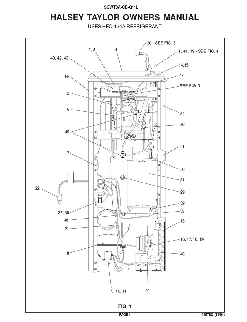
Halsey Taylor SCWT14A-WC-Q 1D Series User manual
Halsey Taylor

Halsey Taylor SCWT14A-WC-Q 1D Series User manual

Halsey Taylor SCWT8A-CB-Q 1P Series User manual

Halsey Taylor

Halsey Taylor SCWT8A-CB-Q 1P Series User manual

Halsey Taylor 4705 User manual

Halsey Taylor

Halsey Taylor 4705 User manual

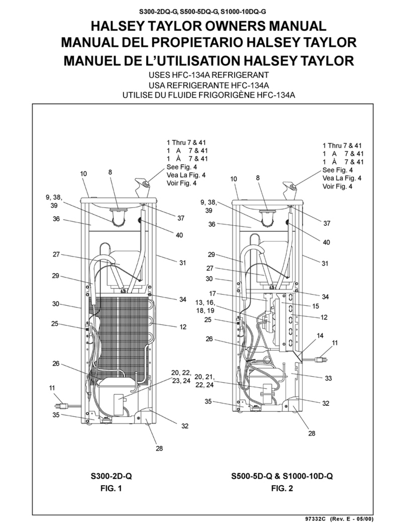
Halsey Taylor SCWT4AQ 1H Series User manual
Halsey Taylor

Halsey Taylor SCWT4AQ 1H Series User manual

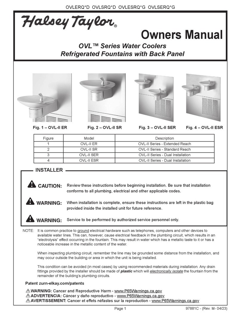
Halsey Taylor HTVZD 1A Series User manual
Halsey Taylor

Halsey Taylor HTVZD 1A Series User manual

Halsey Taylor SCWT4AQ 1F Series User manual

Halsey Taylor

Halsey Taylor SCWT4AQ 1F Series User manual

Popular Plumbing Product manuals by other brands

Grohe StartEdge 23 342 manual

Grohe

Grohe StartEdge 23 342 manual

Harvia Radiant Series Instructions for assembly and use

Harvia

Harvia Radiant Series Instructions for assembly and use

Franke PESCARA PULL DOWN FF4700 installation manual

Franke

Franke PESCARA PULL DOWN FF4700 installation manual

Kraus Indy KBF-1401-2PK quick start guide

Kraus

Kraus Indy KBF-1401-2PK quick start guide

Bradley Bradmar 700 Series Installation

Bradley

Bradley Bradmar 700 Series Installation

Axor Montreux 16510XX1 Installation instructions / warranty

Axor

Axor Montreux 16510XX1 Installation instructions / warranty

Conti+ D35 Installation & user manual

Conti+

Conti+ D35 Installation & user manual

American Standard 283 installation instructions

American Standard

American Standard 283 installation instructions

Sanela Golem SLP 19RZ Instructions for use

Sanela

Sanela Golem SLP 19RZ Instructions for use

DURAVIT 033955 Series Template and mounting instructions

DURAVIT

DURAVIT 033955 Series Template and mounting instructions

Signature Hardware LEXIA 953766 manual

Signature Hardware

Signature Hardware LEXIA 953766 manual

Gessi INGRANAGGIO 63595 manual

Gessi

Gessi INGRANAGGIO 63595 manual

Franke F5 Series Installation and operating instructions

Franke

Franke F5 Series Installation and operating instructions

Signature Hardware Boca Raton 948587 installation instructions

Signature Hardware

Signature Hardware Boca Raton 948587 installation instructions

PEERLESS P99590 Assembly instructions

PEERLESS

PEERLESS P99590 Assembly instructions

GF MULTI/JOINT 3000 Plus user manual

GF

GF MULTI/JOINT 3000 Plus user manual

KaMo HVE-FD instruction manual

KaMo

KaMo HVE-FD instruction manual

Hans Grohe Croma 3jet Series Assembly instructions

Hans Grohe

Hans Grohe Croma 3jet Series Assembly instructions

manuals.online logo
manuals.online logoBrands
  • About & Mission
  • Contact us
  • Privacy Policy
  • Terms and Conditions

Copyright 2025 Manuals.Online. All Rights Reserved.