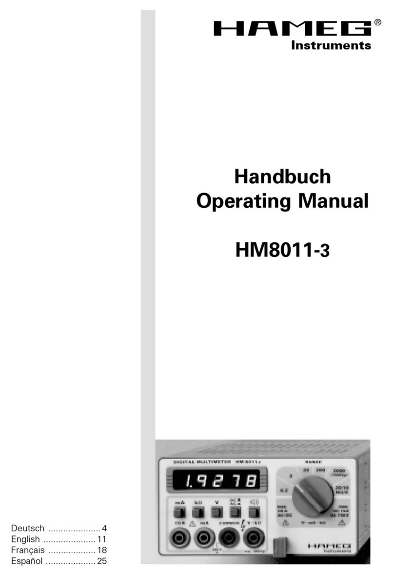
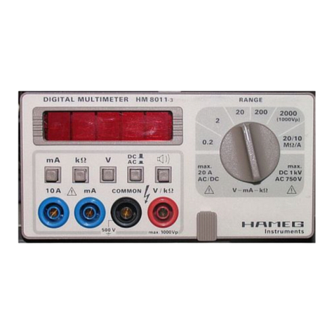
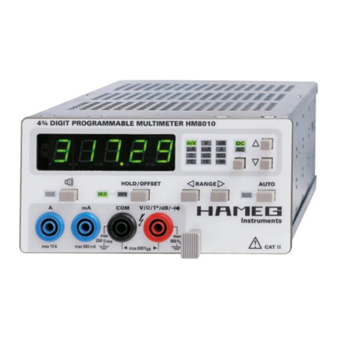
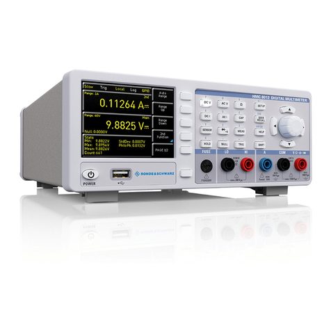
Hameg HMC8012 Operating and maintenance manual

1
HAMEG Instruments GmbH • Industriestr. 6 • D-63533 Mainhausen • Deutschland Subject to change without notice
Tel.: +49 (0) 6182 800 0 • Fax: +49 (0) 6182 800 100 • E-Mail: [email protected]
Geschäftsführer: Dipl.-Ing. Holger Asmussen, Dipl.-Ing. Andre Vander Stichelen • AG Offenbach am Main HRB 41200
1
1
HAMEG Instruments GmbH • Industriestraße 6 • D-63533 Mainhausen Subject to change without notice
Geschäftsführer: Dipl.-Ing. Holger Asmussen • AG Offenbach am Main HRB 41200
Firmware Version: 01.020 and later
English
SCPI Programmers Manual
HMS Series
1
HAMEG Instruments GmbH • Industriestraße 6 • D-63533 Mainhausen Subject to change without notice
Geschäftsführer: Dipl.-Ing. Holger Asmussen • AG Offenbach am Main HRB 41200
Firmware Version: 01.020 and later
English
SCPI Programmers Manual
HMS Series
HMO352x, HMO2524
HMO72x ... HMO202x
Firmware Version: 03.00 and later
English
:ACQuire
:CHAN1OFFSet
:DISPlay
:HCOPy
*ESR?
*OPC?
:LOGic:SIZE
:MEASure
:POD1 :SYSTem
*SRE?
SCPI ProgrammersManual
HMO Series
SCPI Commands HMC8012
English
SCPI ProgrammersManual
HMC8012

2
HAMEG Instruments GmbH • Industriestr. 6 • D-63533 Mainhausen • Deutschland Subject to change without notice
Tel.: +49 (0) 6182 800 0 • Fax: +49 (0) 6182 800 100 • E-Mail: [email protected]
Geschäftsführer: Dipl.-Ing. Holger Asmussen, Dipl.-Ing. Andre Vander Stichelen • AG Offenbach am Main HRB 41200
1
1
HAMEG Instruments GmbH • Industriestraße 6 • D-63533 Mainhausen Subject to change without notice
Geschäftsführer: Dipl.-Ing. Holger Asmussen • AG Offenbach am Main HRB 41200
Firmware Version: 01.020 and later
English
SCPI Programmers Manual
HMS Series
1
HAMEG Instruments GmbH • Industriestraße 6 • D-63533 Mainhausen Subject to change without notice
Geschäftsführer: Dipl.-Ing. Holger Asmussen • AG Offenbach am Main HRB 41200
Firmware Version: 01.020 and later
English
SCPI Programmers Manual
HMS Series
HMO352x, HMO2524
HMO72x ... HMO202x
Firmware Version: 03.00 and later
English
:ACQuire
:CHAN1OFFSet
:DISPlay
:HCOPy
*ESR?
*OPC?
:LOGic:SIZE
:MEASure
:POD1 :SYSTem
*SRE?
SCPI ProgrammersManual
HMO Series
SCPI Commands HMC8012
Inhalt
1.1 Remote Control Interfaces 3
1.1.1 USB Interface 3
1.1.2 LAN Interface 3
1.1.3 GPIB Interface (IEC/IEEE Bus Interface) 4
1.2 Setting Up a Network (LAN) Connection 4
1.2.1 Connecting the Instrument to the Network 4
1.2.2 ConguringLANParameters 4
1.3 Switching to Remote Control 6
1.4 Messages and Command Structure 7
1.4.1 Messages 7
1.4.2 SCPI Command Structure 8
1.5 Command Sequence and Synchronization 12
1.5.1 Preventing Overlapping Execution 13
1.6 Status Reporting System 14
1.6.1 Structure of a SCPI Status Register 14
1.6.2 Hierarchy of status registers 15
1.6.3 Contents of the Status Registers 15
1.6.4 Application of the Status Reporting System 18
2.1 Common Commands 21
2.2 System related commands 23
2.3 Display commands 25
2.4 Trigger commands 26
2.4 CongurationandMeasurementCommands 28
2.4.1 Measurement Commands 28
2.4.2 Congurationcommands 33
2.5 Mathematic Functions 59
2.6 Data and File Management 63
2.7 Status Reporting 69
2.7.1 STATus:OPERation Register 69
2.7.2 STATus:QUEStionable Registers 70

3
HAMEG Instruments GmbH • Industriestr. 6 • D-63533 Mainhausen • Deutschland Subject to change without notice
Tel.: +49 (0) 6182 800 0 • Fax: +49 (0) 6182 800 100 • E-Mail: [email protected]
Geschäftsführer: Dipl.-Ing. Holger Asmussen, Dipl.-Ing. Andre Vander Stichelen • AG Offenbach am Main HRB 41200
1
1
HAMEG Instruments GmbH • Industriestraße 6 • D-63533 Mainhausen Subject to change without notice
Geschäftsführer: Dipl.-Ing. Holger Asmussen • AG Offenbach am Main HRB 41200
Firmware Version: 01.020 and later
English
SCPI Programmers Manual
HMS Series
1
HAMEG Instruments GmbH • Industriestraße 6 • D-63533 Mainhausen Subject to change without notice
Geschäftsführer: Dipl.-Ing. Holger Asmussen • AG Offenbach am Main HRB 41200
Firmware Version: 01.020 and later
English
SCPI Programmers Manual
HMS Series
HMO352x, HMO2524
HMO72x ... HMO202x
Firmware Version: 03.00 and later
English
:ACQuire
:CHAN1OFFSet
:DISPlay
:HCOPy
*ESR?
*OPC?
:LOGic:SIZE
:MEASure
:POD1 :SYSTem
*SRE?
SCPI ProgrammersManual
HMO Series
SCPI Commands HMC8012
1. Introduction / Basics
This chapter provides basic information on operating an instrument via remote control.
1.1 Remote Control Interfaces
For remote control, LAN / USB (standard interface) or GPIB (optional interface) can be used. The optional GPIB inter-
face has its own interface module slot on the rear panel of the HMC8012.
Within this interface description, the term GPIB is used as a synonym for the IEC/IEEE bus interface.
SCPI (Standard Commands for Programmable Instruments) SCPI commands - messages - are used for remote control.
Commands that are not taken from the SCPI standard follow the SCPI syntax rules.
1.1.1 USB Interface
In addition to a LAN interface, the HMC8012 includes a USB device port. For this interface, the user can select if the
instrument is accessed via virtual COM port (VCP) or via USB TMC class. The traditional version of the VCP allows the
user to communicate with the HMC using any terminal program via SCPI commands once the corresponding Windows
drivers have been installed. For the multimeter HMC8012, these commands are mostly compatible with the Agilent
multimeters 34401A and 34410A. Naturally, the free HAMEG software “HMExplorer” is also available for the HMC
series. This Windows application offers HMC instruments a terminal function, the option to create screenshots and to
read out the measured data from the HMC memory.
The modern alternative to the virtual COM port is to remote control the HMC8012 via USB TMC class. TMC stands for
“Test & Measurement Class” which indicates that the connected measurement instrument can be recognized without
special Windows drivers if VISA drivers are installed and that it can be used directly in corresponding environments.
The GPIB interface serves as model to the structure of the TMC design. A major benefit of the USB TMC class is that
by sampling specific registers the controlling software can determine if commands have been terminated and if they
have been processed correctly. In contrast, the communication via VCP requires analysis and polling mechanisms
within the controlling software which may significantly strain the interface of the measurement instruments. The TMC
status registers solve this problem with the USB TMC in the same manner as is the case with the GPIB interface for
the hardware, namely via corresponding control lines.
If you are using USB you need to install an USB driver, which can be downloaded free of charge from the HAMEG
homepage.
The available USB driver is fully tested, functional and released for Windows XP™ 32 Bit, Windows Vista™ or
Windows 7™ both as 32Bit or 64Bit versions.
The USB interface has to be chosen in the multimeter and does not need any setting.
If the virtual COM port will be used, you have to install the virtual COM port part of the HMC8012 USB driver.
The virtual COM port (VCP) will be activated in the PC device explorer.
1.1.2 LAN Interface
The settings of the parameter will be done after selecting the menu item Ethernet and the soft key Parame-
ter. You can set a fix IP adress or a dynamic IP setting via the DHCP function. Please ask your IT department for the
correct setting at your network.
IP address
To set up the connection the IP address of the instrument is required. It is part of the resource string used by the pro-
gram to identify and control the instrument. The resource string has the form:
TCPIP::‹IP_address›::‹IP_port›::SOCKET
The default port number for SCPI socket communication is 5025. IP address and port number are listed In the „Ether-
net Settings“ of the HMC8012, see also: chapter 1.2.2,“Configuring LAN Parameters“, on page 4.

4
HAMEG Instruments GmbH • Industriestr. 6 • D-63533 Mainhausen • Deutschland Subject to change without notice
Tel.: +49 (0) 6182 800 0 • Fax: +49 (0) 6182 800 100 • E-Mail: [email protected]
Geschäftsführer: Dipl.-Ing. Holger Asmussen, Dipl.-Ing. Andre Vander Stichelen • AG Offenbach am Main HRB 41200
1
1
HAMEG Instruments GmbH • Industriestraße 6 • D-63533 Mainhausen Subject to change without notice
Geschäftsführer: Dipl.-Ing. Holger Asmussen • AG Offenbach am Main HRB 41200
Firmware Version: 01.020 and later
English
SCPI Programmers Manual
HMS Series
1
HAMEG Instruments GmbH • Industriestraße 6 • D-63533 Mainhausen Subject to change without notice
Geschäftsführer: Dipl.-Ing. Holger Asmussen • AG Offenbach am Main HRB 41200
Firmware Version: 01.020 and later
English
SCPI Programmers Manual
HMS Series
HMO352x, HMO2524
HMO72x ... HMO202x
Firmware Version: 03.00 and later
English
:ACQuire
:CHAN1OFFSet
:DISPlay
:HCOPy
*ESR?
*OPC?
:LOGic:SIZE
:MEASure
:POD1 :SYSTem
*SRE?
SCPI ProgrammersManual
HMO Series
SCPI Commands HMC8012
Example: If the instrument has the IP address 192.1.2.3; the valid resource string is:
TCPIP::192.1.2.3::5025::SOCKET
If the LAN is supported by a DNS server, the host name can be used instead of the IP address. The DNS server
(Domain Name System server) translates the host name to the IP address. The resource string has the form:
TCPIP::‹host_name›::‹IP_port›::SOCKET
To assign a host name to the HMC8012, select SETUP button › Misc › Device name.
Example: If the host name is HAMEG1; the valid resource string is:
TCPIP::HAMEG1::5025::SOCKET
The end character must be set to linefeed (LF).
1.1.3 GPIB Interface (IEC/IEEE Bus Interface)
In addition to the GPIB functions which are available via USB TMC class, the HMC8012 is optionally available with
an integrated GPIB interface. This solution is particularly attractive for customers who already have an existing GPIB
environment. With minimum efforts, an old instrument can be replaced by a model of the HMC8012.
To be able to control the instrument via the GPIB bus, the instrument and the controller must be linked by a GPIB bus
cable. A GPIB bus card, the card drivers and the program libraries for the programming language must be provided in
the controller. The controller addresses the instrument with the GPIB instrument address.
Characteristics
The GPIB interface is described by the following characteristics:
– Up to 15 instruments can be connected
– The total cable length is restricted to a maximum of 15m; the cable length between two instruments should not exceed
2m.
– A wired „OR“-connection is used if several instruments are connected in parallel.
GPIB Instrument Address
In order to operate the instrument via remote control, it must be addressed using the GPIB address. The remote con-
trol address is factory-set to 20, but it can be changed in the network environment settings or in the „Setup“ menu
under „Interface › Parameter“. For remote control, a GPIB address from 0 to 30 are allowed. The GPIB address is
maintained after a reset of the instrument settings.
1.2 Setting Up a Network (LAN) Connection
1.2.1 Connecting the Instrument to the Network
The network card can be operated with a 10 Mbps Ethernet IEEE 802.3 or a 100 Mbps Ethernet IEEE 802.3u inter-
face.
Risk of network failure
Beforeconnectingtheinstrumenttothenetworkorconguringthenetwork,consultyournetworkadmini-
strator. Errors may affect the entire network.
To establish a network connection, connect a commercial RJ-45 cable to one of the LAN ports of the instru-
ment and to a PC.
1.2.2 ConguringLANParameters
Depending on the network capacities, the TCP/IP address information for the instrument can be obtained in different
ways.
– IfthenetworksupportsdynamicTCP/IPcongurationusingtheDynamicHostCongurationProtocol(DHCP),anda
DHCP server is available, all address information can be assigned automatically.
– Otherwise, the address must be set manually. Automatic Private IP Addressing (APIPA) is not supported.

5
HAMEG Instruments GmbH • Industriestr. 6 • D-63533 Mainhausen • Deutschland Subject to change without notice
Tel.: +49 (0) 6182 800 0 • Fax: +49 (0) 6182 800 100 • E-Mail: [email protected]
Geschäftsführer: Dipl.-Ing. Holger Asmussen, Dipl.-Ing. Andre Vander Stichelen • AG Offenbach am Main HRB 41200
1
1
HAMEG Instruments GmbH • Industriestraße 6 • D-63533 Mainhausen Subject to change without notice
Geschäftsführer: Dipl.-Ing. Holger Asmussen • AG Offenbach am Main HRB 41200
Firmware Version: 01.020 and later
English
SCPI Programmers Manual
HMS Series
1
HAMEG Instruments GmbH • Industriestraße 6 • D-63533 Mainhausen Subject to change without notice
Geschäftsführer: Dipl.-Ing. Holger Asmussen • AG Offenbach am Main HRB 41200
Firmware Version: 01.020 and later
English
SCPI Programmers Manual
HMS Series
HMO352x, HMO2524
HMO72x ... HMO202x
Firmware Version: 03.00 and later
English
:ACQuire
:CHAN1OFFSet
:DISPlay
:HCOPy
*ESR?
*OPC?
:LOGic:SIZE
:MEASure
:POD1 :SYSTem
*SRE?
SCPI ProgrammersManual
HMO Series
SCPI Commands HMC8012
By default, the instrument is configured to use dynamic TCP/IP configuration and obtain all address information au-
tomatically. This means that it is safe to establish a physical connection to the LAN without any previous instrument
configuration.
Risk of network errors
Connection errors can affect the entire network. If your network does not support DHCP, or if you choose
todisabledynamicTCP/IPconguration,youmustassignvalidaddressinformationbeforeconnectingthe
instrumenttotheLAN.ContactyournetworkadministratortoobtainavalidIPaddress.
Conguring LAN parameters
1. Press the SETUP key and then the Interface softkey.
2. Press the Ethernet and then the Parameter softkey.
Note:Bydefault,theinstrumentissettonotuseDHCP.IftheinstrumentissettouseDHCPandcannotndaDHCP
server, it takes about two minutes until the Ethernet menu is available.
The „Ethernet Settings“ dialog box is displayed.
Fig. 1.1: Ethernet Settings dialog box
Some data is displayed for information only and cannot be edited. This includes the „MAC“ (physical) address of the
connector and the „Link“ status information.
4. DenetheIPaddressoftheinstrumentbyenteringeachofthefourblocksindividually(manualmode)orchoosethe
automatic IP-Mode.
a) Inmanualmode(MAN)denetherstblocknumberusingtheknob.
b) Press Nexttomovetothenextblockanddenethenumber.
c) When the IP address is complete, press Down to continue with the next setting.
5. Denethe„Subnetmask“and„Gateway“inthesameway.
6. Select the „RAW Port“ - the port number for SCPI socket communication.
7. Select the „VXI-11- Port“ used by the instrument.
8. Select the „Transfer“ mode. This mode can either be determined automatically („Auto“ setting), or you can select a
combination of a transfer rate and half or full duplex manually.
9. Press Save to save the LAN parameters.

6
HAMEG Instruments GmbH • Industriestr. 6 • D-63533 Mainhausen • Deutschland Subject to change without notice
Tel.: +49 (0) 6182 800 0 • Fax: +49 (0) 6182 800 100 • E-Mail: [email protected]
Geschäftsführer: Dipl.-Ing. Holger Asmussen, Dipl.-Ing. Andre Vander Stichelen • AG Offenbach am Main HRB 41200
1
1
HAMEG Instruments GmbH • Industriestraße 6 • D-63533 Mainhausen Subject to change without notice
Geschäftsführer: Dipl.-Ing. Holger Asmussen • AG Offenbach am Main HRB 41200
Firmware Version: 01.020 and later
English
SCPI Programmers Manual
HMS Series
1
HAMEG Instruments GmbH • Industriestraße 6 • D-63533 Mainhausen Subject to change without notice
Geschäftsführer: Dipl.-Ing. Holger Asmussen • AG Offenbach am Main HRB 41200
Firmware Version: 01.020 and later
English
SCPI Programmers Manual
HMS Series
HMO352x, HMO2524
HMO72x ... HMO202x
Firmware Version: 03.00 and later
English
:ACQuire
:CHAN1OFFSet
:DISPlay
:HCOPy
*ESR?
*OPC?
:LOGic:SIZE
:MEASure
:POD1 :SYSTem
*SRE?
SCPI ProgrammersManual
HMO Series
SCPI Commands HMC8012
The „Link“ and „IP-Status“ information at the bottom of the dialog box indicates whether a LAN connection
was established successfully.
Checking LAN and SCPI connection
1. Check the LAN connection using ping: ping xxx.yyy.zzz.xxx.
2. If the PC can access the instrument, enter the IP address of the address line of the internet browser on your computer:
http//:xxx.yyy.zzz.xxx
The „Instrument Home“ page appears. It provides information on the instrument and the LAN connection.
Fig.1.2:Webserver
1.3 Switching to Remote Control
When you switch on the instrument, it is always in manual operation state („local“ state) and can be operated via the
front panel.
When you send a command from the control computer, it will be received and executed by the instrument. The display
remains on, manual operation via the front panel is always possible.

7
HAMEG Instruments GmbH • Industriestr. 6 • D-63533 Mainhausen • Deutschland Subject to change without notice
Tel.: +49 (0) 6182 800 0 • Fax: +49 (0) 6182 800 100 • E-Mail: [email protected]
Geschäftsführer: Dipl.-Ing. Holger Asmussen, Dipl.-Ing. Andre Vander Stichelen • AG Offenbach am Main HRB 41200
1
1
HAMEG Instruments GmbH • Industriestraße 6 • D-63533 Mainhausen Subject to change without notice
Geschäftsführer: Dipl.-Ing. Holger Asmussen • AG Offenbach am Main HRB 41200
Firmware Version: 01.020 and later
English
SCPI Programmers Manual
HMS Series
1
HAMEG Instruments GmbH • Industriestraße 6 • D-63533 Mainhausen Subject to change without notice
Geschäftsführer: Dipl.-Ing. Holger Asmussen • AG Offenbach am Main HRB 41200
Firmware Version: 01.020 and later
English
SCPI Programmers Manual
HMS Series
HMO352x, HMO2524
HMO72x ... HMO202x
Firmware Version: 03.00 and later
English
:ACQuire
:CHAN1OFFSet
:DISPlay
:HCOPy
*ESR?
*OPC?
:LOGic:SIZE
:MEASure
:POD1 :SYSTem
*SRE?
SCPI ProgrammersManual
HMO Series
SCPI Commands HMC8012
1.4 Messages and Command Structure
1.4.1 Messages
Instrument messages are employed in the same way for all interfaces, if not indicated otherwise in the description.
See also:
– Structure and syntax of the instrument messages: chapter 1.4.2, „SCPI Command Structure“, on page 7
– Detailed description of all messages: chapter 2, „Command Reference“, on page 20
There are different types of instrument messages:
– Commands
– Instrument responses
Commands
Commands (program messages) are messages which the controller sends to the instrument. They operate the instru-
ment functions and request information. The commands are subdivided according to two criteria:
1. According to the effect they have on the instrument:
– Setting commands cause instrument settings such as a reset of the instrument or setting the frequency.
– Queriescausedatatobeprovidedforremotecontrol,e.g.foridenticationoftheinstrumentorpollinga
parameter value. Queries are formed by directly appending a question mark to the command header.
2. According to their denition in standards:
– The function and syntax of the Common commands arepreciselydenedinstandardIEEE488.2.Theyare
employed identically on all instruments (if implemented). They refer to functions such as management
of the standardized status registers, reset and self test.
– Instrument control commands refer to functions depending on the features of the instrument such as
frequency settings. Many of these commands have also been standardized by the SCPI committee. These
commands are marked as „SCPI compliant“ in the command reference chapters. Commands without this
SCPIlabelaredevice-specic,however,theirsyntaxfollowsSCPIrulesaspermittedbythestandard.
Instrument responses
Instrument responses (response messages and service requests) are messages which the instrument is sent to the
controller after a query. They can contain measurement results, instrument settings and information on the instrument
status.
GPIB Interface Messages
Interface messages are transmitted to the instrument on the data lines, with the attention line (ATN) being active
(LOW). They are used for communication between the controller and the instrument and can only be sent by a compu-
ter which has the function of a GPIB bus controller. GPIB interface messages can be further subdivided into:
– Universalcommands: act on all instruments connected to the GPIB bus without previous addressing
– Addressed commands: only act on instruments previously addressed as listeners
Universal Commands
Universal commands are encoded in the range 10 through 1F hex. They affect all instruments connected to the bus
and do not require addressing.
Addressed commands are encoded in the range 00 through 0F hex. They only affect instruments addressed as
listeners.

8
HAMEG Instruments GmbH • Industriestr. 6 • D-63533 Mainhausen • Deutschland Subject to change without notice
Tel.: +49 (0) 6182 800 0 • Fax: +49 (0) 6182 800 100 • E-Mail: [email protected]
Geschäftsführer: Dipl.-Ing. Holger Asmussen, Dipl.-Ing. Andre Vander Stichelen • AG Offenbach am Main HRB 41200
1
1
HAMEG Instruments GmbH • Industriestraße 6 • D-63533 Mainhausen Subject to change without notice
Geschäftsführer: Dipl.-Ing. Holger Asmussen • AG Offenbach am Main HRB 41200
Firmware Version: 01.020 and later
English
SCPI Programmers Manual
HMS Series
1
HAMEG Instruments GmbH • Industriestraße 6 • D-63533 Mainhausen Subject to change without notice
Geschäftsführer: Dipl.-Ing. Holger Asmussen • AG Offenbach am Main HRB 41200
Firmware Version: 01.020 and later
English
SCPI Programmers Manual
HMS Series
HMO352x, HMO2524
HMO72x ... HMO202x
Firmware Version: 03.00 and later
English
:ACQuire
:CHAN1OFFSet
:DISPlay
:HCOPy
*ESR?
*OPC?
:LOGic:SIZE
:MEASure
:POD1 :SYSTem
*SRE?
SCPI ProgrammersManual
HMO Series
SCPI Commands HMC8012
1.4.2 SCPI Command Structure
SCPI commands consist of a so-called header and, in most cases, one or more parameters. The header and the para-
meters are separated by a „white space“ (ASCII code 0 to 9, 11 to 32 decimal, e.g. blank). The headers may consist of
several mnemonics (keywords). Queries are formed by appending a question mark directly to the header.
The commands can be either device-specific or device-independent (common commands). Common and device-speci-
fic commands differ in their syntax.
Syntax for Common Commands
Common (= device-independent) commands consist of a header preceded by an asterisk (*) and possibly one or more
parameters.
Examples:
*RST RESET Resets the instrument.
*ESE EVENT STATUS ENABLE Sets the bits of the event status enable registers.
*ESR? EVENT STATUS QUERY Queries the contents of the event status register.
*IDN? IDENTIFICATION QUERY Queries the instrument identification string.
Table 1.4: Examples of Common Commands
Syntax for Device-Specic Commands
Not all commands used in the following examples are necessarily implemented in the instrument.
For demonstration purposes only, assume the existence of the following commands for this section:
- CALCulate:FUNCtion {NULL | DB | DBM | AVERage | LIMit}
- CALCulate:FUNCtion?
- CALCulate[:STATe] {OFF | ON}
- C A L C u l a t e[:S T A T e]?
Long and short form
The mnemonics feature a long form and a short form. The short form is marked by upper case letters, the long form
corresponds to the complete word. Either the short form or the long form can be entered; other abbreviations are not
permitted.
Example:
CALCulate:FUNCtion NULL is equivalent to CALC:FUNC NULL
Case-insensitivity
Uppercaseandlowercasenotationonlyservestodistinguishthetwoformsinthemanual,theinstrument
itselfiscase-insensitive.

9
HAMEG Instruments GmbH • Industriestr. 6 • D-63533 Mainhausen • Deutschland Subject to change without notice
Tel.: +49 (0) 6182 800 0 • Fax: +49 (0) 6182 800 100 • E-Mail: [email protected]
Geschäftsführer: Dipl.-Ing. Holger Asmussen, Dipl.-Ing. Andre Vander Stichelen • AG Offenbach am Main HRB 41200
1
1
HAMEG Instruments GmbH • Industriestraße 6 • D-63533 Mainhausen Subject to change without notice
Geschäftsführer: Dipl.-Ing. Holger Asmussen • AG Offenbach am Main HRB 41200
Firmware Version: 01.020 and later
English
SCPI Programmers Manual
HMS Series
1
HAMEG Instruments GmbH • Industriestraße 6 • D-63533 Mainhausen Subject to change without notice
Geschäftsführer: Dipl.-Ing. Holger Asmussen • AG Offenbach am Main HRB 41200
Firmware Version: 01.020 and later
English
SCPI Programmers Manual
HMS Series
HMO352x, HMO2524
HMO72x ... HMO202x
Firmware Version: 03.00 and later
English
:ACQuire
:CHAN1OFFSet
:DISPlay
:HCOPy
*ESR?
*OPC?
:LOGic:SIZE
:MEASure
:POD1 :SYSTem
*SRE?
SCPI ProgrammersManual
HMO Series
SCPI Commands HMC8012
Optional mnemonics
Some command systems permit certain mnemonics to be inserted into the header or omitted. These mnemonics are
marked by square brackets in the description. The instrument must recognize the long command to comply with the
SCPI standard. Some commands are considerably shortened by these optional mnemonics.
Example:
INITiate[:IMMediate]
Definition: INITiate[:IMMediate]
Command: INIT:IMM is equivalent to INIT
Special characters
| Parameters
A vertical stroke in parameter definitions indicates alternative possibilities in the sense of „or“. The
effect of the command differs, depending on which parameter is used.
Example:
Definition: UNIT:TEMPerature {C | K | F}
Command: UNIT:TEMP C selects °C for temperature measurements
Command: UNIT:TEMP K selects Kelvins for temperature measurements
[ ] Mnemonics in square brackets are optional and may be inserted into the header or omitted.
Example: INITiate[:IMMediate]
INIT:IMM is equivalent to INIT
{ } Parameters in curly brackets are optional and can be inserted once or several times, or omitted.
Example: CALCulate:LIMit:LOWer {<Value> | MINimum | MAXimum}
The following are valid commands:
CALC:LIM:LOW 10
CALC:LIM:LOW MIN
CALC:LIM:LOW MAX
Table 1.5: Special characters
SCPI Parameters
Many commands are supplemented by a parameter or a list of parameters. The parameters must be separated from
the header by a „white space“ (ASCII code 0 to 9, 11 to 32 decimal, e.g. blank). Allowed parameters are:
– Numeric values
– Special numeric values
– Boolean parameters
– Text
– Character strings
– Block data
The parameters required for each command and the allowed range of values are specified in the command description.

10
HAMEG Instruments GmbH • Industriestr. 6 • D-63533 Mainhausen • Deutschland Subject to change without notice
Tel.: +49 (0) 6182 800 0 • Fax: +49 (0) 6182 800 100 • E-Mail: [email protected]
Geschäftsführer: Dipl.-Ing. Holger Asmussen, Dipl.-Ing. Andre Vander Stichelen • AG Offenbach am Main HRB 41200
1
1
HAMEG Instruments GmbH • Industriestraße 6 • D-63533 Mainhausen Subject to change without notice
Geschäftsführer: Dipl.-Ing. Holger Asmussen • AG Offenbach am Main HRB 41200
Firmware Version: 01.020 and later
English
SCPI Programmers Manual
HMS Series
1
HAMEG Instruments GmbH • Industriestraße 6 • D-63533 Mainhausen Subject to change without notice
Geschäftsführer: Dipl.-Ing. Holger Asmussen • AG Offenbach am Main HRB 41200
Firmware Version: 01.020 and later
English
SCPI Programmers Manual
HMS Series
HMO352x, HMO2524
HMO72x ... HMO202x
Firmware Version: 03.00 and later
English
:ACQuire
:CHAN1OFFSet
:DISPlay
:HCOPy
*ESR?
*OPC?
:LOGic:SIZE
:MEASure
:POD1 :SYSTem
*SRE?
SCPI ProgrammersManual
HMO Series
SCPI Commands HMC8012
Numeric values
Numeric values can be entered in any form, i.e. with sign, decimal point and exponent. Values exceeding the resolution
of the instrument are rounded up or down. The mantissa may comprise up to 255 characters, the exponent must lie
inside the value range -32000 to 32000. The exponent is introduced by an „E“ or „e“. Entry of the exponent alone is
not allowed. In the case of physical quantities, the unit can be entered. Allowed unit prefixes are MA (mega) / MOHM,
K (kilo), M (milli) and U (micro). If the unit is missing, the basic unit is used.
Example: CALC:NULL:OFF 10mV = CALC:NULL:OFF 10E-3
Special numeric values
The texts listed below are interpreted as special numeric values. In the case of a query, the numeric value is provided.
– MIN/MAX
MINimum and MAXimum denote the minimum and maximum value.
Example:
Setting command: CALCulate:LIMit:LOWer MAXimum
Query: CALC:LIM:LOW MAX?, Response: 1E3
Queriesforspecialnumericvalues
ThenumericvaluesassociatedtoMAXimum/MINimumcanbequeriedbyaddingthecorrespondingmnemo-
nicstothecommand.Theymustbeenteredfollowingthequotationmark.
Example: CALC:LIM:LOW? MAXimum
Returns the maximum numeric value as a result.
Boolean parameters
Boolean parameters represent two states. The „ON“ state (logically true) is represented by „ON“ or a numeric value
1. The „OFF“ state (logically untrue) is represented by „OFF“ or the numeric value 0. The numeric values are provided
as the response for a query.
Example:
Setting command: CALCulate[:STATe] ON
Query: CALC:STAT?
Response: 1
Text parameters
Text parameters observe the syntactic rules for mnemonics, i.e. they can be entered using a short or long form. Like
any parameter, they have to be separated from the header by a white space. In the case of a query, the short form of
the text is provided.
Example:
Setting command: HCOPy:FORMat BMP
Query: HCOPy:FORMat?
Response: BMP

11
HAMEG Instruments GmbH • Industriestr. 6 • D-63533 Mainhausen • Deutschland Subject to change without notice
Tel.: +49 (0) 6182 800 0 • Fax: +49 (0) 6182 800 100 • E-Mail: [email protected]
Geschäftsführer: Dipl.-Ing. Holger Asmussen, Dipl.-Ing. Andre Vander Stichelen • AG Offenbach am Main HRB 41200
1
1
HAMEG Instruments GmbH • Industriestraße 6 • D-63533 Mainhausen Subject to change without notice
Geschäftsführer: Dipl.-Ing. Holger Asmussen • AG Offenbach am Main HRB 41200
Firmware Version: 01.020 and later
English
SCPI Programmers Manual
HMS Series
1
HAMEG Instruments GmbH • Industriestraße 6 • D-63533 Mainhausen Subject to change without notice
Geschäftsführer: Dipl.-Ing. Holger Asmussen • AG Offenbach am Main HRB 41200
Firmware Version: 01.020 and later
English
SCPI Programmers Manual
HMS Series
HMO352x, HMO2524
HMO72x ... HMO202x
Firmware Version: 03.00 and later
English
:ACQuire
:CHAN1OFFSet
:DISPlay
:HCOPy
*ESR?
*OPC?
:LOGic:SIZE
:MEASure
:POD1 :SYSTem
*SRE?
SCPI ProgrammersManual
HMO Series
SCPI Commands HMC8012
Overview of Syntax Elements
The following table provides an overview of the syntax elements:
: The colon separates the mnemonics of a command. In a command line the separating semicolon-
marks the uppermost command level.
; The semicolon separates two commands of a command line. It does not alter the path.
, The comma separates several parameters of a command.
? The question mark forms a query.
* The asterisk marks a common command.
“ Quotation marks introduce a string and terminate it.
A „white space“ (ASCII-Code 0 to 9, 11 to 32 decimal, e.g. blank) separates the header from the
parameters.
Table 1.6: Syntax Elements
Structure of a command line
A command line may consist of one or several commands. It is terminated by one of the following:
– a ‹New Line›
– a ‹New Line›with EOI
– an EOI together with the last data byte
Several commands in a command line must be separated by a semicolon „;“. If the next command belongs to a diffe-
rent command system, the semicolon is followed by a colon.
If the successive commands belong to the same system, having one or several levels in common, the command line
can be abbreviated. To this end, the second command after the semicolon starts with the level that lies below the
common levels. The colon following the semicolon must be omitted in this case.
Example: CALC:FUNC NULL; CALC ON
This command line is represented in its full length and contains two commands separated from each other by the
semicolon. Both commands are part of the CALC command system, i.e. they have one level in common. When abbre-
viating the command line, the second command begins with the level below CALC The colon after the semicolon is
omitted. The abbreviated form of the command line reads as follows:
CALC:FUNC NULL;ON
A new command line always begins with the complete path.
Example: CALC:FUNC NULL
CALC ON
Responses to Queries
A query is defined for each setting command unless explicitly specified otherwise. It is formed by adding a question
mark to the associated setting command. According to SCPI, the responses to queries are partly subject to stricter
rules than in standard IEEE 488.2.
– The requested parameter is transmitted without a header.
Example: HCOPy:FORMat?,
Response: BMP

12
HAMEG Instruments GmbH • Industriestr. 6 • D-63533 Mainhausen • Deutschland Subject to change without notice
Tel.: +49 (0) 6182 800 0 • Fax: +49 (0) 6182 800 100 • E-Mail: [email protected]
Geschäftsführer: Dipl.-Ing. Holger Asmussen, Dipl.-Ing. Andre Vander Stichelen • AG Offenbach am Main HRB 41200
1
1
HAMEG Instruments GmbH • Industriestraße 6 • D-63533 Mainhausen Subject to change without notice
Geschäftsführer: Dipl.-Ing. Holger Asmussen • AG Offenbach am Main HRB 41200
Firmware Version: 01.020 and later
English
SCPI Programmers Manual
HMS Series
1
HAMEG Instruments GmbH • Industriestraße 6 • D-63533 Mainhausen Subject to change without notice
Geschäftsführer: Dipl.-Ing. Holger Asmussen • AG Offenbach am Main HRB 41200
Firmware Version: 01.020 and later
English
SCPI Programmers Manual
HMS Series
HMO352x, HMO2524
HMO72x ... HMO202x
Firmware Version: 03.00 and later
English
:ACQuire
:CHAN1OFFSet
:DISPlay
:HCOPy
*ESR?
*OPC?
:LOGic:SIZE
:MEASure
:POD1 :SYSTem
*SRE?
SCPI ProgrammersManual
HMO Series
SCPI Commands HMC8012
– Maximum values, minimum values and all other quantities that are requested via a special text parameter are returned
as numeric values.
Example: CALCulate:LIMit:LOWer? MAXimum,
Response: 1E3
– Numeric values are output without a unit. Physical quantities are referred to the basic units or to the units set using the
Unit command. The response 3.5E9 in the previous example stands for 3.5 GHz.
– Truth values (Boolean values) are returned as 0 (for OFF) and 1 (for ON).
Example:
Setting command: CALCulate:STATe ON
Query: CALCulate:STATe?
Response: 1
1.5 Command Sequence and Synchronization
IEEE 488.2 defines a distinction between overlapped and sequential commands:
– Asequentialcommandnishesexecutingbeforethenextcommandstartsexecuting.Commandsthatareprocessed
quickly are usually implemented as sequential commands.
– Anoverlappingcommanddoesnotautomaticallynishexecutingbeforethenextcommandstartsexecuting.Usually,
overlapping commands take longer to process and allow the program to do other tasks while being executed. If over-
lappingcommandsdohavetobeexecutedinadenedorder,e.g.inordertoavoidwrongmeasurementresults,they
must be serviced sequentially. This is called synchronization between the controller and the instrument.
Setting commands within one command line, even though they may be implemented as sequential commands, are
not necessarily serviced in the order in which they have been received. In order to make sure that commands are actu-
ally carried out in a certain order, each command must be sent in a separate command line.
Example: Commands and queries in one message
The response to a query combined in a program message with commands that affect the queried value is not predictable.
The following commands always return the specified result:
:CALC:FUNC DB;CALC:STAT ON;CALC:DB:REF MAX :CALC:DB:REF?
Result: 7.500E+02
Asageneralrule,sendcommandsandqueriesindifferentprogrammessages.

13
HAMEG Instruments GmbH • Industriestr. 6 • D-63533 Mainhausen • Deutschland Subject to change without notice
Tel.: +49 (0) 6182 800 0 • Fax: +49 (0) 6182 800 100 • E-Mail: [email protected]
Geschäftsführer: Dipl.-Ing. Holger Asmussen, Dipl.-Ing. Andre Vander Stichelen • AG Offenbach am Main HRB 41200
1
1
HAMEG Instruments GmbH • Industriestraße 6 • D-63533 Mainhausen Subject to change without notice
Geschäftsführer: Dipl.-Ing. Holger Asmussen • AG Offenbach am Main HRB 41200
Firmware Version: 01.020 and later
English
SCPI Programmers Manual
HMS Series
1
HAMEG Instruments GmbH • Industriestraße 6 • D-63533 Mainhausen Subject to change without notice
Geschäftsführer: Dipl.-Ing. Holger Asmussen • AG Offenbach am Main HRB 41200
Firmware Version: 01.020 and later
English
SCPI Programmers Manual
HMS Series
HMO352x, HMO2524
HMO72x ... HMO202x
Firmware Version: 03.00 and later
English
:ACQuire
:CHAN1OFFSet
:DISPlay
:HCOPy
*ESR?
*OPC?
:LOGic:SIZE
:MEASure
:POD1 :SYSTem
*SRE?
SCPI ProgrammersManual
HMO Series
SCPI Commands HMC8012
1.5.1 Preventing Overlapping Execution
To prevent an overlapping execution of commands, one of the commands *OPC, *OPC? or *WAI can be used. All
three commands cause a certain action only to be carried out after the hardware has been set. By suitable program-
ming, the controller can be forced to wait for the corresponding action to occur.
Command Action Programming the controller
*OPC Sets the Operation Complete bit in the
ESRafter all previous commands have
been executed.
– Setting bit 0 in the ESE
– Setting bit 5 in the SRE
– Waiting for service request (SRQ)
*OPC? Stops command processing until 1 is
returned.This is only the case after the
Opera-tion Complete bit has been set
in the ESR. This bit indicates that the
previous setting has been completed.
Sending *OPC? directly after the command whose
processing should be terminated before other com-
mands can be executed.
*WAI Stops further command processing until
allcommands sent before *WAI have
been executed.
Sending *WAI directly after the command whose
processing should be terminated before other com-
mands are executed
Table 1.7: Synchronization using *OPC, *OPC? and *WAI
Command synchronization using *WAI or *OPC? appended to an overlapped command is a good choice if the overlap-
ped command takes time to process. The two synchronization techniques simply block overlapped execution of the
command.
For time consuming overlapped commands it is usually desirable to allow the controller or the instrument to do other
useful work while waiting for command execution. Use one of the following methods:
*OPC with a service request
1. Set the OPC mask bit (bit no. 0) in the ESE: *ESE 1
2. Set bit no. 5 in the SRE: *SRE 32 to enable ESB service request.
3. Send the overlapped command with *OPC
4. Wait for a service request
Theservicerequestindicatesthattheoverlappedcommandhasnished.
*OPC? with a service request
1. Set bit no. 4 in the SRE: *SRE 16 to enable MAV service request.
2. Send the overlapped command with *OPC?
3. Wait for a service request
Theservicerequestindicatesthattheoverlappedcommandhasnished.
Event Status Register (ESE)
1. Set the OPC mask bit (bit no. 0) in the ESE: *ESE 1
2. Send the overlapped command without *OPC, *OPC? or *WAI
3. Poll the operation complete state periodically (by means of a timer) using the sequence: *OPC; *ESR?
Areturnvalue(LSB)of1indicatesthattheoverlappedcommandhasnished.

14
HAMEG Instruments GmbH • Industriestr. 6 • D-63533 Mainhausen • Deutschland Subject to change without notice
Tel.: +49 (0) 6182 800 0 • Fax: +49 (0) 6182 800 100 • E-Mail: [email protected]
Geschäftsführer: Dipl.-Ing. Holger Asmussen, Dipl.-Ing. Andre Vander Stichelen • AG Offenbach am Main HRB 41200
1
1
HAMEG Instruments GmbH • Industriestraße 6 • D-63533 Mainhausen Subject to change without notice
Geschäftsführer: Dipl.-Ing. Holger Asmussen • AG Offenbach am Main HRB 41200
Firmware Version: 01.020 and later
English
SCPI Programmers Manual
HMS Series
1
HAMEG Instruments GmbH • Industriestraße 6 • D-63533 Mainhausen Subject to change without notice
Geschäftsführer: Dipl.-Ing. Holger Asmussen • AG Offenbach am Main HRB 41200
Firmware Version: 01.020 and later
English
SCPI Programmers Manual
HMS Series
HMO352x, HMO2524
HMO72x ... HMO202x
Firmware Version: 03.00 and later
English
:ACQuire
:CHAN1OFFSet
:DISPlay
:HCOPy
*ESR?
*OPC?
:LOGic:SIZE
:MEASure
:POD1 :SYSTem
*SRE?
SCPI ProgrammersManual
HMO Series
SCPI Commands HMC8012
*OPC? with short timeout
1. Send the overlapped command without *OPC, *OPC? or *WAI
2. Poll the operation complete state periodically (by means of a timer) using the sequence: ‹short timeout›; *OPC?
3. Areturnvalue(LSB)of1indicatesthattheoverlappedcommandhasnished.Incaseofatimeout,theoperationis
ongoing.
4. Reset timeout to former value
5. Clear the error queue with SYStem:ERRor? to remove the „-410, Query interrupted“ entries.
Using several threads in the controller application
As an alternative, provided the programming environment of the controller application supports threads, separate
threads can be used for the application GUI and for controlling the instrument(s) via SCPI.
A thread waiting for a *OPC? thus will not block the GUI or the communication with other instruments.
1.6 Status Reporting System
The status reporting system stores all information on the current operating state of the instrument, and on errors
which have occurred. This information is stored in the status registers and in the error queue. Both can be queried via
GPIB bus or LAN interface (STATus... commands).
1.6.1 Structure of a SCPI Status Register
Each standard SCPI register consists of 5 parts. Each part has a width of 16 bits and has different functions. The
individual bits are independent of each other, i.e. each hardware status is assigned a bit number which is valid for all
five parts. Bit 15 (the most significant bit) is set to zero for all parts. Thus the contents of the register parts can be
processed by the controller as positive integers.
Description of the ve status register parts (please refer to page 20)
The five parts of a SCPI register have different properties and functions:
– CONDition
The CONDitionpartiswrittenintodirectlybythehardwareorthesumbitofthenextlowerregister.Itscontentsreect
the current instrument status. This register part can only be read, but not written into or cleared. Its contents are not
affected by reading.
– EVENt
The EVENt part indicates whether an event has occurred since the last reading, it is the „memory“ of the condition part.
Itonlyindicateseventspassedonbythetransitionlters.Itispermanentlyupdatedbytheinstrument.Thispartcan
only be read by the user. Reading the register clears it. This part is often equated with the entire register.
– ENABle
The ENABle part determines whether the associated EVENt bit contributes to the sum bit (see below). Each bit of the
EVENt part is „ANDed“ with the associated ENABle bit (symbol ‚&‘). The results of all logical operations of this part are
passed on to the sum bit via an „OR“ function (symbol ‚+‘).
ENABle bit = 0: the associated EVENt bit does not contribute to the sum bit ENABle bit = 1: if the associated EVENt bit
is „1“, the sum bit is set to „1“ as well. This part can be written into and read by the user as required. Its contents are
not affected by reading.
Sum bit
The sum bit is obtained from the EVENt and ENABle part for each register. The result is then entered into a bit of the
CONDition part of the higher-order register.
The instrument automatically generates the sum bit for each register. Thus an event can lead to a service request
throughout all levels of the hierarchy.

15
HAMEG Instruments GmbH • Industriestr. 6 • D-63533 Mainhausen • Deutschland Subject to change without notice
Tel.: +49 (0) 6182 800 0 • Fax: +49 (0) 6182 800 100 • E-Mail: [email protected]
Geschäftsführer: Dipl.-Ing. Holger Asmussen, Dipl.-Ing. Andre Vander Stichelen • AG Offenbach am Main HRB 41200
1
1
HAMEG Instruments GmbH • Industriestraße 6 • D-63533 Mainhausen Subject to change without notice
Geschäftsführer: Dipl.-Ing. Holger Asmussen • AG Offenbach am Main HRB 41200
Firmware Version: 01.020 and later
English
SCPI Programmers Manual
HMS Series
1
HAMEG Instruments GmbH • Industriestraße 6 • D-63533 Mainhausen Subject to change without notice
Geschäftsführer: Dipl.-Ing. Holger Asmussen • AG Offenbach am Main HRB 41200
Firmware Version: 01.020 and later
English
SCPI Programmers Manual
HMS Series
HMO352x, HMO2524
HMO72x ... HMO202x
Firmware Version: 03.00 and later
English
:ACQuire
:CHAN1OFFSet
:DISPlay
:HCOPy
*ESR?
*OPC?
:LOGic:SIZE
:MEASure
:POD1 :SYSTem
*SRE?
SCPI ProgrammersManual
HMO Series
SCPI Commands HMC8012
1.6.2 Hierarchy of status registers
The status information has an hierarchical structure.
– STB, SRE
The STatus Byte (STB) register and its associated mask register Service Request Enable (SRE) form the highest level of
the status reporting system. The STB provides a rough overview of the instrument status, collecting the information of
the lower-level registers.
– ESR, SCPI registers
The STB receives its information from the following registers:
– The Event Status Register (ESR) with the associated mask register standard Event Status Enable (ESE).
– The STATus:OPERation and STATus:QUEStionableregisterswhicharedenedbySCPIandcontaindetailed
instrument information.
– Output buffer
The output buffer contains the messages the instrument returns to the controller. It is not part of the status reporting
system, but determines the value of the MAV bit in the STB and thus is represented in the overview.
All status registers have the same internal structure.
SRE, ESE
TheservicerequestenableregisterSRE can be used as ENABle part of the STB if the STB is structured
according to SCPI. By analogy, the ESE can be used as the ENABle part of the ESR.
1.6.3 Contents of the Status Registers
In the following sections, the contents of the status registers are described more detailed (please refer to page 20).
Status Byte (STB) and Service Request Enable Register (SRE)
The STatus Byte (STB) is already defined in IEEE 488.2. It provides a rough overview of the instrument status by
collecting the pieces of information of the lower registers. A special feature is that bit 6 acts as the sum bit of the
remaining bits of the status byte.
The STB can thus be compared with the CONDition part of an SCPI register and assumes the highest level within the
SCPI hierarchy.
The STB is using the command *STB or a serial poll.
The STatus Byte (STB) is linked to the Service Request Enable (SRE) register. Each bit of the STB is assigned a
bit in the SRE. Bit 6 of the SRE is ignored. If a bit is set in the SRE and the associated bit in the STB changes from 0 to
1, a service request (SRQ) is generated. The SRE can be set by using the command *SRE and can be read by using the
command *SRE?.

16
HAMEG Instruments GmbH • Industriestr. 6 • D-63533 Mainhausen • Deutschland Subject to change without notice
Tel.: +49 (0) 6182 800 0 • Fax: +49 (0) 6182 800 100 • E-Mail: [email protected]
Geschäftsführer: Dipl.-Ing. Holger Asmussen, Dipl.-Ing. Andre Vander Stichelen • AG Offenbach am Main HRB 41200
1
1
HAMEG Instruments GmbH • Industriestraße 6 • D-63533 Mainhausen Subject to change without notice
Geschäftsführer: Dipl.-Ing. Holger Asmussen • AG Offenbach am Main HRB 41200
Firmware Version: 01.020 and later
English
SCPI Programmers Manual
HMS Series
1
HAMEG Instruments GmbH • Industriestraße 6 • D-63533 Mainhausen Subject to change without notice
Geschäftsführer: Dipl.-Ing. Holger Asmussen • AG Offenbach am Main HRB 41200
Firmware Version: 01.020 and later
English
SCPI Programmers Manual
HMS Series
HMO352x, HMO2524
HMO72x ... HMO202x
Firmware Version: 03.00 and later
English
:ACQuire
:CHAN1OFFSet
:DISPlay
:HCOPy
*ESR?
*OPC?
:LOGic:SIZE
:MEASure
:POD1 :SYSTem
*SRE?
SCPI ProgrammersManual
HMO Series
SCPI Commands HMC8012
Bit No. Meaning
0...1 Not used
2 Error Queue
The bit is set when an error is occured. If this bit is enabled by the SRE, each entry of the error
queue generates a service request. Thus an error can be recognized and specified in greater detail
by polling the error queue. The poll provides an informative error message. This procedure is to be
recommended since it considerably reduces the problems involved with remote control.
3 QUEStionable status sum bit
The bit is set, if an EVENt bit is set in the QUEStionable status register and the associated ENABle
bit is set to 1. A set bit indicates a questionable instrument status, which can be specified in detail
by polling the QUEStionable status register.
4 MAV bit (message available)
The bit is set, if a readable message in the output buffer is available. This bit can be used to enable
data to be automatical read from the instrument.
5 ESB bit
Sum bit of the event status register. It is set, if one of the bits in the event status register is set and
enabled in the event status enable register. Setting of this bit indicates a serious error, which can be
specified in greater detail by polling the event status register.
6 MSS bit (master status summary bit)
The bit is set, if the instrument triggers a service request. This is the case, if one of the other bits of
this register is set together with its mask bit in the service request enable register SRE.
7OPERation status register sum bit
The bit is set, if an EVENt bit is set in the OPERation status register and the associated ENABle bit
is set to 1. A set bit indicates that the instrument is just performing an action. The type of action can
be determined by polling the OPERation status register.
Table 1.8: Bits of the status byte (please refer to page 20)
Event Status Register (ESR) and Event Status Enable Register (ESE)
The ESR is defined in IEEE 488.2. It can be compared with the EVENt part of a SCPI register. The event status register
can be read out using command *ESR?.
The ESE corresponds to the ENABle part of a SCPI register. If a bit is set in the ESE and the associated bit in the ESR
changes from 0 to 1, the ESB bit in the STB is set. The ESE register can be set using the command *ESE and read
using the command *ESE?.

17
HAMEG Instruments GmbH • Industriestr. 6 • D-63533 Mainhausen • Deutschland Subject to change without notice
Tel.: +49 (0) 6182 800 0 • Fax: +49 (0) 6182 800 100 • E-Mail: [email protected]
Geschäftsführer: Dipl.-Ing. Holger Asmussen, Dipl.-Ing. Andre Vander Stichelen • AG Offenbach am Main HRB 41200
1
1
HAMEG Instruments GmbH • Industriestraße 6 • D-63533 Mainhausen Subject to change without notice
Geschäftsführer: Dipl.-Ing. Holger Asmussen • AG Offenbach am Main HRB 41200
Firmware Version: 01.020 and later
English
SCPI Programmers Manual
HMS Series
1
HAMEG Instruments GmbH • Industriestraße 6 • D-63533 Mainhausen Subject to change without notice
Geschäftsführer: Dipl.-Ing. Holger Asmussen • AG Offenbach am Main HRB 41200
Firmware Version: 01.020 and later
English
SCPI Programmers Manual
HMS Series
HMO352x, HMO2524
HMO72x ... HMO202x
Firmware Version: 03.00 and later
English
:ACQuire
:CHAN1OFFSet
:DISPlay
:HCOPy
*ESR?
*OPC?
:LOGic:SIZE
:MEASure
:POD1 :SYSTem
*SRE?
SCPI ProgrammersManual
HMO Series
SCPI Commands HMC8012
Bit No. Meaning
0 Operation Complete
This bit is set on receipt of the command *OPC exactly, when all previous commands have been
executed.
1 Not used
2 Query Error
This bit is set, if either the controller wants to read data from the instrument without having sent a
query, or if it does not fetch requested data and sends new instructions to the instrument instead.
The cause is often a query which is faulty and hence cannot be executed.
3 Device-dependent Error
This bit is set, if a device-dependent error occurs. An error message with a number between -300
and -399 or a positive error number is entered into the error queue.
4 Execution Error
This bit is set if a received command is syntactically correct, but cannot be performed for other rea-
sons. An error message with a number between -200 and -300 is entered into the error queue.
5 Command Error
This bit is set, if a command is received, which is undefined or syntactically incorrect. An error mes-
sage with a number between -100 and -200 is entered into the error queue.
6 Not used
7 Power On (supply voltage on)
This bit is set, when switching on the instrument.
Table1.9:Bitsoftheeventstatusregister(please refer to page 20)
STATus:OPERation Register
In the CONDition part, the register contains information which operations the instrument is being executing. In the
EVENt part, it contains information which operations the instrument has executed since the last reading. It can be read
using the commands STATus:OPERation:CONDition? or STATus:OPERation[:EVENt]?.
The remote commands for the STATus:OPERation register are described on page 65.
Bit No. Meaning
0Calibrating
(for service department only)
1 to 3 Not used
4Measuring
The bit is set, while the instrument is measuring.
5Waiting for Trig
This bit is set while the instrument is waiting for the trigger.
6 to 9 Not used
10 Instrument Locked (RWLock)
11 to 15 Not used
Table 1.10: Bits of the STATus:OPERation register (please refer to page 20)

18
HAMEG Instruments GmbH • Industriestr. 6 • D-63533 Mainhausen • Deutschland Subject to change without notice
Tel.: +49 (0) 6182 800 0 • Fax: +49 (0) 6182 800 100 • E-Mail: [email protected]
Geschäftsführer: Dipl.-Ing. Holger Asmussen, Dipl.-Ing. Andre Vander Stichelen • AG Offenbach am Main HRB 41200
1
1
HAMEG Instruments GmbH • Industriestraße 6 • D-63533 Mainhausen Subject to change without notice
Geschäftsführer: Dipl.-Ing. Holger Asmussen • AG Offenbach am Main HRB 41200
Firmware Version: 01.020 and later
English
SCPI Programmers Manual
HMS Series
1
HAMEG Instruments GmbH • Industriestraße 6 • D-63533 Mainhausen Subject to change without notice
Geschäftsführer: Dipl.-Ing. Holger Asmussen • AG Offenbach am Main HRB 41200
Firmware Version: 01.020 and later
English
SCPI Programmers Manual
HMS Series
HMO352x, HMO2524
HMO72x ... HMO202x
Firmware Version: 03.00 and later
English
:ACQuire
:CHAN1OFFSet
:DISPlay
:HCOPy
*ESR?
*OPC?
:LOGic:SIZE
:MEASure
:POD1 :SYSTem
*SRE?
SCPI ProgrammersManual
HMO Series
SCPI Commands HMC8012
STATus:QUEStionable Register
This register contains information about indefinite states which may occur, if the unit is operated without meeting the
specifications. It can be read using the commands STATus:QUEStionable:CONDition on page 66 and STATus:
QUEStionable[:EVENt] on page 67.
Bit No. Meaning
0 Voltage overrange
This bit is set, if a voltage range overload occurs.
1 Current overrange
This bit is set if a current range overload occurs.
2 to 3 Not used
4Temperature overrange
This bit is set if a temperature range overload occurs.
5 Frequency overload / underflow
This bit is set if a frequency range overload / underflow occurs.
6 to 8 Not used
9 Resistance overrange
This bit is set if a resistance range overload occurs.
10 Capacitance overload / underflow
This bit is set if a capacitance range overload / underflow occurs.
11 Lower limit failed
This bit is set if a lower limit value is violated.
12 Upper limit failed
This bit is set if an upper limit value is violated.
13 to 15 Not used
Table 1.11: Bits of the STATus:QUEStionable register (please refer to page 20)
1.6.4 Application of the Status Reporting System
The purpose of the status reporting system is to monitor the status of one or several devices in a measuring system.
The controller must receive and evaluate the information of all devices. The following standard methods are used:
– Servicerequest (SRQ) initiated by the instrument
– Serial pollofalldevicesinthebussystem,initiatedbythecontrollerinordertondoutwhosentaSRQandwhy
– Parallel poll of all devices
– Query of a specicinstrumentstatus by means of commands
– Query of the errorqueue
Serial Poll
In a serial poll, with command *STB the status byte of an instrument is queried. The query is realized via interface mes-
sages and thus clearly faster. The serial poll method is defined in IEEE 488.1 and used to be the standard possibility for
different instruments to poll the status byte. The method also works for instruments, which do not adhere to SCPI or
IEEE 488.2.
The serial poll is mainly used to obtain a fast overview of the state of several instruments connected to the controller.

19
HAMEG Instruments GmbH • Industriestr. 6 • D-63533 Mainhausen • Deutschland Subject to change without notice
Tel.: +49 (0) 6182 800 0 • Fax: +49 (0) 6182 800 100 • E-Mail: [email protected]
Geschäftsführer: Dipl.-Ing. Holger Asmussen, Dipl.-Ing. Andre Vander Stichelen • AG Offenbach am Main HRB 41200
1
1
HAMEG Instruments GmbH • Industriestraße 6 • D-63533 Mainhausen Subject to change without notice
Geschäftsführer: Dipl.-Ing. Holger Asmussen • AG Offenbach am Main HRB 41200
Firmware Version: 01.020 and later
English
SCPI Programmers Manual
HMS Series
1
HAMEG Instruments GmbH • Industriestraße 6 • D-63533 Mainhausen Subject to change without notice
Geschäftsführer: Dipl.-Ing. Holger Asmussen • AG Offenbach am Main HRB 41200
Firmware Version: 01.020 and later
English
SCPI Programmers Manual
HMS Series
HMO352x, HMO2524
HMO72x ... HMO202x
Firmware Version: 03.00 and later
English
:ACQuire
:CHAN1OFFSet
:DISPlay
:HCOPy
*ESR?
*OPC?
:LOGic:SIZE
:MEASure
:POD1 :SYSTem
*SRE?
SCPI ProgrammersManual
HMO Series
SCPI Commands HMC8012
Query of an instrument status
Each part of any status register can be read using queries. There are two types of commands:
– The common commands *ESR?, *IDN?, *STB? query the higher-level registers.
– The commands of the STATus system query the SCPI registers (STATus:QUEStionable...)
The returned value is always a decimal number that represents the bit pattern of the queried register. This number is
evaluated by the controller program.
Queries are usually used after an SRQ in order to obtain more detailed information on the SRQ cause.
Decimal representation of a bit pattern (binary weights)
The STB and ESR registers contain 8 bits, the SCPI registers 16 bits. The contents of a status register are specified
and transferred as a single decimal number. To make this possible, each bit is assigned a weighted value. The decimal
number is calculated as the sum of the weighted values of all bits in the register that are set to 1.
Remote Control
R&S®RTM
192User Manual 1305.0595.02 ─ 03
The serial poll method is defined in IEEE 488.1 and used to be the only standard possibility for different instruments to poll the status byte. The method also works for instru-
ments which do not adhere to SCPI or IEEE 488.2.
The serial poll is mainly used to obtain a fast overview of the state of several instruments
connected to the controller.
Query of an instrument status
Each part of any status register can be read using queries. There are two types of com
mands:
●The common commands *ESR?, *IDN?, *IST?, *STB? query the higher-level reg
isters.
●The commands of the STATus system query the SCPI registers
(STATus:QUEStionable...)
The returned value is always a decimal number that represents the bit pattern of the
queried register. This number is evaluated by the controller program.
Queries are usually used after an SRQ in order to obtain more detailed information on
the cause of the SRQ.
Decimal representation of a bit pattern
The STB and ESR registers contain 8 bits, the SCPI registers 16 bits. The contents of a
status register are specified and transferred as a single decimal number. To make this
possible, each bit is assigned a weighted value. The decimal number is calculated as the
sum of the weighted values of all bits in the register that are set to 1.
Example:
The decimal value 40 = 32 + 8 indicates that bits no. 3 and 5 in the status register (e.g.
the QUEStionable status summary bit and the ESB bit in the STatus Byte ) are set.
Error Queue
Each error state in the instrument leads to an entry in the error queue. The entries of the
error queue are detailed plain text error messages that can be looked up in the Error Log
or queried via remote control using SYSTem:ERRor[:NEXT]? or
SYSTem:ERRor:ALL?. Each call of SYSTem:ERRor[:NEXT]? provides one entry from
the error queue. If no error messages are stored there any more, the instrument responds
with 0, "No error".
The error queue should be queried after every SRQ in the controller program as the
entries describe the cause of an error more precisely than the status registers. Especially
Basics
Fig. 1.7: Decimal representation of a bit pattern (please refer to page 20)
Example:
The decimal value 40 = 32 + 8 indicates that bits no. 3 and 5 in the status register (e.g. the QUEStionable status
summary bit and the ESB bit in the STatus Byte ) are set.
Error Queue
Each error state in the instrument leads to an entry in the error queue. The entries of the error queue are de-
tailed plain text error messages that can be looked up in the error log or queried via remote control using
SYSTem:ERRor[:NEXT]?. Each call of SYSTem:ERRor[:NEXT]? provides one entry from the error queue. If no error
messages are stored, the instrument responds with 0, „No error“.
The error queue should be queried after every SRQ in the controller program as the entries describe the cause of an er-
ror more precisely than the status registers. Especially in the test phase of a controller program the error queue should
be queried regularly since faulty commands from the controller to the instrument are recorded there as well.

20
HAMEG Instruments GmbH • Industriestr. 6 • D-63533 Mainhausen • Deutschland Subject to change without notice
Tel.: +49 (0) 6182 800 0 • Fax: +49 (0) 6182 800 100 • E-Mail: [email protected]
Geschäftsführer: Dipl.-Ing. Holger Asmussen, Dipl.-Ing. Andre Vander Stichelen • AG Offenbach am Main HRB 41200
1
1
HAMEG Instruments GmbH • Industriestraße 6 • D-63533 Mainhausen Subject to change without notice
Geschäftsführer: Dipl.-Ing. Holger Asmussen • AG Offenbach am Main HRB 41200
Firmware Version: 01.020 and later
English
SCPI Programmers Manual
HMS Series
1
HAMEG Instruments GmbH • Industriestraße 6 • D-63533 Mainhausen Subject to change without notice
Geschäftsführer: Dipl.-Ing. Holger Asmussen • AG Offenbach am Main HRB 41200
Firmware Version: 01.020 and later
English
SCPI Programmers Manual
HMS Series
HMO352x, HMO2524
HMO72x ... HMO202x
Firmware Version: 03.00 and later
English
:ACQuire
:CHAN1OFFSet
:DISPlay
:HCOPy
*ESR?
*OPC?
:LOGic:SIZE
:MEASure
:POD1 :SYSTem
*SRE?
SCPI ProgrammersManual
HMO Series
SCPI Commands HMC8012
Questionable Data Register
2
3
4
5
–
7
0
1
2
3
4
5
6
7
Enable Register
Condition Register
“OR“
0
1
2
3
4
5
6
7
Operation Complete (OPC) 0
1
Query Error 2
Divice Error 3
Execution Error 4
Command Error 5
6
Power ON 7
Enable Register
Event Register
“OR“
0
1
2
3
4
5
6
7
8
9
10
11
12
13
14
15
Event Register
Condition Register
“OR“
0
1
2
3
4
5
6
7
8
9
10
11
12
13
14
15
Enable Register
Voltage Overload 0
Current Overload 1
2
3
Temperature Overload 4
FrequencyOverload/Underow 5
6
7
8
Resistance Overload 9
CapacitanceOverload/Underow 10
Lower Limit Failed 11
Upper Limit Failed 12
13
14
15
0
1
2
3
4
5
6
7
8
9
10
11
12
13
14
15
Event Register
Condition Register
“OR“
0
1
2
3
4
5
6
7
8
9
10
11
12
13
14
15
Enable Register
Calibrating 0
1
2
3
Measuring 4
Wating for Trigger 5
6
7
8
9
Instrument Locked 10
11
12
13
14
15
1
20
Data
Data
Error Queue Status Byte RegisterOutput Buffer
Standard Event Register Standard Operation Register Binary Weights
STATus:QUES:COND?
STATus:QUES:EVENt?
STATus:QUES:ENABle
STATus:QUES:ENABle?
STATus:OPER:COND?
STATus:OPER:EVENt?
STATus:OPER:ENABle
STATus:OPER:ENABle?
*ESE
*ESE?
*ESR?
SYSTem:ERRor?
Serial Poll
*STB?
*SRE
*SRE?
Summary Bit (RQS)
2
0
= 1
2
1
= 2
2
2
= 4
2
3
= 8
2
4
= 16
2
5
= 32
2
6
= 64
2
7
= 128
2
8
= 256
2
9
= 512
2
10
= 1024
2
11
= 2048
2
12
= 4096
2
13
= 8192
2
14
= 16384
2
15
= 32768
Other manuals for HMC8012
2
Table of contents
Other Hameg Multimeter manuals

Hameg
Hameg HM8112-3 User manual

Hameg
Hameg HM 8012 User manual

Hameg
Hameg HM 8012 User manual

Hameg
Hameg HM 8012 User manual

Hameg
Hameg HM8112-3S User manual

Hameg
Hameg HM8112-3 User manual

Hameg
Hameg HM 8040-2 User manual

Hameg
Hameg HM 8012 User manual

Hameg
Hameg HM 8012 User manual

Hameg
Hameg HM 8012 User manual