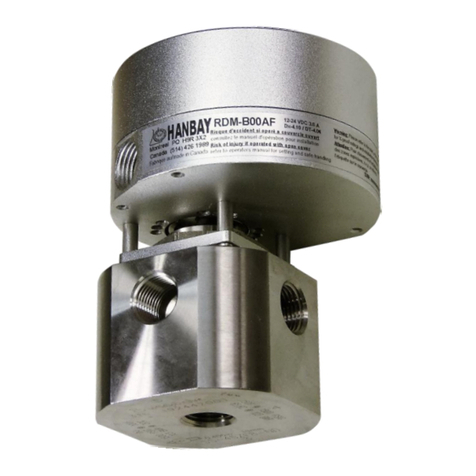
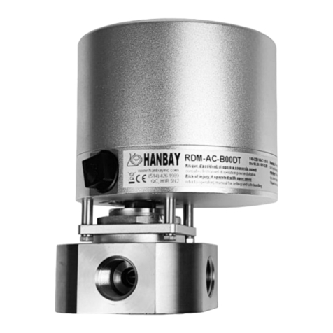
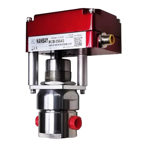
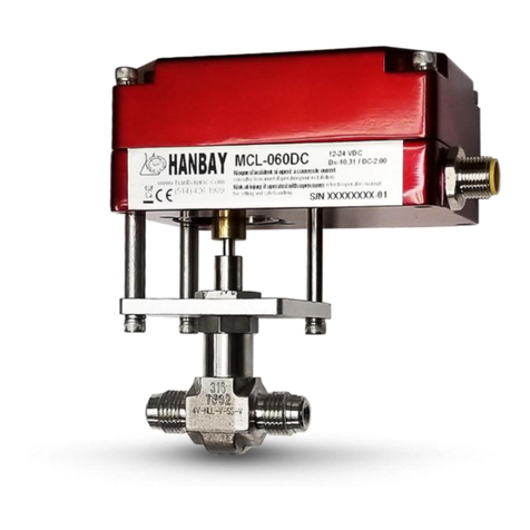
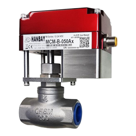
Hanbay RC AS-1.05 Series User manual

HANBAY Inc User Manual RCx-xxxAS-1.05
Page 1 of 15 www.hanbayinc.com
Rev.2018.1 1 800 315 4461
hanbaysales@hanbayinc.com
RCx-xxxAS -1.05
Contents
Installation pg. 1-3
Mounting pg. 1
Wiring pg. 2
Connecting signal and power pg. 2-3
Serial port connections pg. 3
Operation pg. 4-6
DIP Switch pg. 4
Recalibration pg. 4
Troubleshooting pg. 4
Communications parameters pg. 5
Speed and Torque details pg. 5-6
Appendix pg. 7-14
Modbus Protocol pg. 7-12
Power settings pg. 8
Signal/power loss pg 10-11
Setting actuator address pg. 13
Dimensions pg. 14
Part Number Breakdown pg. 15
Installation
Mounting:
Wiring:
Holes for a mounting bracket. Holes
are threaded for ¼-20 and are
approximately .275” deep.
For dimensions see page 9

HANBAY Inc User Manual RCx-xxxAS-1.05
Page 2 of 15 www.hanbayinc.com
Rev.2018.1 1 800 315 4461
hanbaysales@hanbayinc.com
The actuator comes standard with a Turck 6 position connector and a 20’ cable with plug. Cut the cable to the
length required and then connect according to the following wire color schematic:
Wire color schematic for “Turck6” cable:
Pin
Colour
DC power supply only
6
White
+24VDC
5
Black
Power Gnd
4
Pink
TD(A)
3
Grey
TD(B)
2
Brown
Isolated*Input Signal Gnd
1
Blue
Isolated*Input + Signal (4..20mA)
Connect the power:
The RCx may be connected to voltages ranging from: 12 –24 VDC.
18 VDC is required for full ‘Digital Potentiometer’ functionality (see pg. 7)
The power consumption will range from max. 3.0A to approx.. min. 100mA
when the actuator is active. When not moving, the actuator draws less
than 50mA.
Terminal
123456
GND
V+
DC Voltages
1 2 3 4 5 6
P
1
Turck connector
not included in CSA
rated explosion
proof enclosures

HANBAY Inc User Manual RCx-xxxAS-1.05
Page 3 of 15 www.hanbayinc.com
Rev.2018.1 1 800 315 4461
hanbaysales@hanbayinc.com
Serial Port Connection:
Connect the signal:
Locate the correct connection terminals as shown in the picture above then
connect your input signal on pos. 3 and 4 as shown below.
ACTUATOR
1 2 3 4 5 6
P2
4 .. 20mA Signal source,
user powered
-
+
TD(A) TD(B)
SIGNAL GND
RCx
Internal
RES
R66
NOTE 1: Usually, the actuators are shipped for
4 .. 20mA signal input.
For 1 ..5 V signal input, remove 250 ohm resistor
R66 (or cut just one wire as shown in picture on
page 2)
NOTE 2: Signal Gnd is ISOLATED from
Power Gnd. in all RCx-xxxSImodels.

HANBAY Inc User Manual RCx-xxxAS-1.05
Page 4 of 15 www.hanbayinc.com
Rev.2018.1 1 800 315 4461
hanbaysales@hanbayinc.com
Operation
DIP switches:
The DIP switches allow you to change the
settings on your actuator. To flip a switch,
gently use a small flat-head screwdriver.
See chart on next page for DIP switch functionality.
Direction of rotation:
To change the direction of rotation, turn off the actuator, change the position of switch DIP 12 and power it up again.
Calibration:
The actuator will re-zero when the input signal is between 2.8 and 4.16mA (0.700V –1.040V). It will turn either
clockwise or anti-clockwise (depending on direction selection of DIP 12) until the actuator has reached the fully closed
position of the valve.
If you need to re-zero the actuator because you have changed the valve, while the actuator is on, toggle DIP12
wait one second and then put it back or use the command code 0x64. In both cases you will see the actuator closing
the valve very slowly.
Troubleshooting:
Upon noticing a problem, your first step should almost always be to recalibrate the actuator by switching DIP 12,
then switching it back to its original position, all while the actuator is powered. This alone can solve basic problems.
See section 3 on this page for more details.
If the actuator does not move, try following these steps:
1) Re-calibrate the actuator. This will move the actuator regardless of what signal it is receiving.
2) A sticking valve may be the problem. Remove the valve from the actuator, and re-test the actuator.
3) Remove power. Re-check the wiring and the power/signal apparatus. Power actuator, and re-calibrate.
If the problem persists, please call Hanbay for technical support.
DIP switches. In this example DIPs 1, 2, 6 and 12 are on.
It is VERY important that you put back DIP12. If you do not that, the actuator will turn in the opposite direction
next time you power it up.

HANBAY Inc User Manual RCx-xxxAS-1.05
Page 5 of 15 www.hanbayinc.com
Rev.2018.1 1 800 315 4461
hanbaysales@hanbayinc.com
Set the communication parameters:
Data bits: 8
Parity: None
Stop bits: 1
Baud Rate: The communication baud rate can be set by using the first two positions of the DIP switch selector.
Check in the table below. (1 = “On” 0 = “Off”).
To change the baud rate, turn off the actuator, change the setting of DIP switches and power it up again.
DIP 1
DIP 2
Baud rate
0
0
2400 bps
0
1
4800 bps
1
0
9600 bps
1
1
19200 bps
Response time: The response time is between 8ms to 35ms, this means, after sending a frame, you have to wait at
least 35ms for the answer coming back from the actuator
Speed and Torque Details:
To set the maximum speed change the value of address 0x0000: (This speed setting will only limit the maximum speed)
The faster you set this maximum speed, the less torque you can expect at this maximum speed, as shown in the
tables below.
NOTE: Depending ONLY on the power setting address 0x0001, the actuator will supply up to the maximum torque,
by automatically slowing down when the torque demand increases.
IMPORTANT: For every speed setting the maximum torque is the torque shown at the minimum speed = 0
Speed and Torque of RCL-xxxAS Actuators .
Maximum Speed
Address 0x0000
Time for
1 Turn
(sec)
Torque in in-lbs
0x0001 = 0
16% Power
Torque in in-lbs
0x0001 = 1
33% Power
Torque in in-lbs
0x0001 = 2
66% Power
Torque in in-lbs
0x0001 = 3
100% Power
12VDC
24VDC
12VDC
24VDC
12VDC
24VDC
12VDC
24VDC
0
7
6
12
10
20
19
38
20
40
1
3
Operating torque is 100% These torque values are for valve seating.
2
2
3
1
To convert in-lbs to Nm, divide the in-lbs value by 9
Warning: High power settings can supply enough torque to damage
your valve. Please be cautious, especially when using the 100%
power setting.

HANBAY Inc User Manual RCx-xxxAS-1.05
Page 6 of 15 www.hanbayinc.com
Rev.2018.1 1 800 315 4461
hanbaysales@hanbayinc.com
Speed and Torque of RCM-xxxAS Actuators
Maximum Speed
Address 0x0000
Time for
1 Turn
(sec)
Torque in in-lbs
0x0001 = 0
16% Power
Torque in in-lbs
0x0001 = 1
33% Power
Torque in in-lbs
0x0001 = 2
66% Power
Torque in in-lbs
0x0001 = 3
100% Power
12VDC
24VDC
12VDC
24VDC
12VDC
24VDC
12VDC
24VDC
0
23
17
35
28
60
57
115
70
145
1
11
Operating torque is 100% These torque values are for valve seating.
2
7
3
4
To convert in-lbs to Nm, divide the in-lbs value by 9
Speed and Torque of RCH-xxxAS Actuators
Maximum Speed
Address 0x0000
Time for
1 Turn
(sec)
Torque in in-lbs
0x0001 = 0
16% Power
Torque in in-lbs
0x0001 = 1
33% Power
Torque in in-lbs
0x0001 = 2
66% Power
Torque in in-lbs
0x0001 = 3
100% Power
12VDC
24VDC
12VDC
24VDC
12VDC
24VDC
12VDC
24VDC
0
90
44
120
88
205
166
400
245
497
1
45
Operating torque is 100% These torque values are for valve seating.
2
30
3
18
To convert in-lbs to Nm, divide the in-lbs value by 9
Speed and Torque of RCF-xxxAS Actuators
Maximum Speed
Address 0x0000
Time for
1 Turn
(sec)
Torque in in-lbs
0x0001 = 0
16% Power
Torque in in-lbs
0x0001 = 1
33% Power
Torque in in-lbs
0x0001 = 2
66% Power
Torque in in-lbs
0x0001 = 3
100% Power
12VDC
24VDC
12VDC
24VDC
12VDC
24VDC
12VDC
24VDC
0
161
112
230
170
380
360
720
450
915
1
77
Operating torque is 100% These torque values are for valve seating.
2
49
3
28
To convert in-lbs to Nm, divide the in-lbs value by 9
Speed and Torque of RCU-xxxAx Actuators
Time for
1 turn
(sec)
12VDC 24VDC 12VDC 24VDC 12VDC 24VDC 12VDC 24VDC
OFF OFF 713 490 990 1330 1674 1600 3209 2020 4045
OFF ON 341
ON OFF 217
ON ON 124
DIP 1
DIP 2
Torque in in-lbs
Torque in in-lbs
Torque in in-lbs
Torque in in-lbs
16% Power*
33% Power*
66% Power*
100% Power*
Note: 66% setting and 100% setting may alter duty cycle:
-When operating above 66% power, Duty cycle is reduced to 50% - 25% maximum. At these
levels, the electronics produce more heat which must be dissipated (depending on environmental
temperature and torque of the valve).

HANBAY Inc User Manual RCx-xxxAS-1.05
Page 7 of 15 www.hanbayinc.com
Rev.2018.1 1 800 315 4461
hanbaysales@hanbayinc.com
Appendix
MODBUS protocol:
Actuator parameters can be set by using the MODBUS (RTU) protocol.
Standard supported function codes:
02 (0x02) Read Discrete Inputs
03 (0x03) Read Holding Registers.
04 (0x04) Read Input Registers.
06 (0x06) Write Single Register.
Hanbay function codes:
100 (0x64) Re-zero the actuator.
101 (0x65) Close the valve.
102 (0x66) Open the valve.
Actuator memory map:
Address
(DEC)
Address (HEX)
Offset
Register Name
Type
0
0x0000
4001
MaximumSpeed
Holding registers.
READ and WRITE
1
0x0001
4002
MaximumPower
2
0x0002
4003
NumberOfTurns
3
0x0003
4004
TargetFromRS485Flag
4
0x0004
4005
InputRangeLow
5
0x0005
4006
InputRangeHigh
6
0x0006
4007
OutputRangeLow
7
0x0007
4008
OutputRangeHigh
8
0x0008
4009
TargetPosition
9
0x0009
4010
SignalLostPosition
10
0x000A
4011
Reserved
11
0x000B
4012
Reserved
12
0x000C
4013
Reserved
13
0x000D
4014
Reserved
14
0x000E
4015
Reserved
15
0x000F
4016
Reserved
16
0x0010
4017
Reserved
17
0x0011
4018
Reserved
18
0x0012
4019
Reserved
19
0x0013
4020
Reserved
20
0x0014
4021
CurrentPosition
Input registers.
READ only
21
0x0015
4022
StatusRegister
If you try to use any other function code, the actuator will answer with the exception code 0x01
indicating that
the attempted function code is not supported.

HANBAY Inc User Manual RCx-xxxAS-1.05
Page 8 of 15 www.hanbayinc.com
Rev.2018.1 1 800 315 4461
hanbaysales@hanbayinc.com
Register name
Address
Max
Min
Default
Actuator
address
Function
code
Register
address
Register
new value
CRC
MaximumSpeed
0x0000
3
0
N/A
Example: Set Maximum speed to 0 in actuator number 8
0x08
0x06
0x0000
0x0000
0x----
1 byte
1 byte
2 bytes
2 bytes
2
bytes
Register name
Address
Max
Min
Default
Actuator
address
Function
code
Register
address
Register
new value
CRC
MaximumPower
0x0001
3
0
N/A
Example: Set Maximum power to 3 in actuator number 9
0x09
0x06
0x0001
0x0003
0x----
1 byte
1 byte
2 bytes
2 bytes
2
bytes
Possible values are shown in the following table.
Maximum Power value
Power level
0
16%
1
33%
2
66%
3
100%
Effect of power settings and speed settings:
To accommodate different valves and other applications, with different torque requirements, the actuator can be set
to apply different torque on the valve stem when in the seating mode.
The actuator will try to reach the speed set by “MaximumSpeed”. If the torque required is too high, the actuator will
automatically slow down and deliver the maximum available torque for a given “Permanent Power Setting”,
i.e: the torque shown in line 1 of each of the tables above.
To deal with sticking valves, at the beginning of the first reversing movement after the seating (“zeroing”) of the valve,
the actuator will apply double the power set by “MaximumPower” (up to 100% power.)
This “pull out” function is always enabled.
IMPORTANT: All the values send to the actuator are “HEX” values
Register name
Address
Max
Min
Default
Actuator
address
Function
code
Register
address
Register
new value
CRC
NumberOfTurns
0x0002
100
1
N/A
Example: Set number of turns to 32 in actuator number 10
0x0A
0x06
0x0002
0x0020
0x----
1 byte
1 byte
2 bytes
2 bytes
2
bytes
Note: 66% setting and 100% setting may change duty cycle:
When operating above 20VDC and 66% power, Duty cycle is reduced to 50% - 25% maximum. At these
levels, the electronics produce more heat which must be dissipated (depending on environmental
temperature and torque requirements).

HANBAY Inc User Manual RCx-xxxAS-1.05
Page 9 of 15 www.hanbayinc.com
Rev.2018.1 1 800 315 4461
hanbaysales@hanbayinc.com
Register name
Address
Max
Min
Default
Actuator
address
Function
code
Register
address
Register
new value
CRC
TargetFromRS485Flag
0x0003
2
0
N/A
Example: To have actuator number 11 taking the target
position from the “TargetPosition” register
0x0B
0x06
0x0003
0x0000
0x----
1 byte
1 byte
2 bytes
2 bytes
2
bytes
This flag tells the actuator where the target position is coming from. If this value is 1 the actuator will take the value
from 4..20mA input as its target position. If this value is 0 the actuator will take the value from “TargetPosition”
register as its target position.
(Remember: all values sent to actuator are HEX)
Register name
Address
Max
Min
Default
Actuator
address
Function
code
Register
address
Register
new value
CRC
InputRangeLow
0x0004
64900
0
0
Example: Set input range low to 4000 in actuator number
12
0x0C
0x06
0x0004
0x0FA0
0x----
1 byte
1 byte
2 bytes
2 bytes
2
bytes
Register name
Address
Max
Min
Default
Actuator
address
Function
code
Register
address
Register
new value
CRC
InputRangeHigh
0x0005
65000
100
10000
Example: Set input range high to 65000 in actuator number
23
0x17
0x06
0x0005
0xFDE8
0x----
1 byte
1 byte
2 bytes
2 bytes
2
bytes
For a detailed explanation of this two registers please see “TargetPosition” register description.
Register name
Address
Max
Min
Default
Actuator
address
Function
code
Register
address
Register
New
value
CRC
OutputRangeLow
0x0006
64900
0
0
Example: Set input range low to 4000 in actuator number
12
0x0C
0x06
0x0006
0x0FA0
0x----
1 byte
1 byte
2 bytes
2 bytes
2
bytes
Register name
Address
Max
Min
Default
Actuator
address
Function
code
Register
address
Register
new value
CRC
OutputRangeHigh
0x0007
65000
100
10000
Example: Set input range high to 65000 in actuator number
23
0x17
0x06
0x0007
0xFDE8
0x----
1 byte
1 byte
2 bytes
2 bytes
2
bytes
For a detailed explanation of this two registers please see “CurrentPosition” register description.
The value stored in “InputRangeLow” register must always be lower than the one stored in “InputRangeHigh”.
If you try to write an illogical range, the actuator will answer with exception code 0x03 indicating that the new
value is not valid. (Remember: all values sent to actuator are HEX)
The value stored in “OutputRangeLow” register must always be lower than the one stored in
“OutputRangeHigh”. If you try to write an illogical range, the actuator will answer with exception code 0x03
indicating that the new value is not valid. (Remember: all values sent to actuator are HEX)

HANBAY Inc User Manual RCx-xxxAS-1.05
Page 10 of 15 www.hanbayinc.com
Rev.2018.1 1 800 315 4461
hanbaysales@hanbayinc.com
Register name
Address
Max
Min
Def.
Actuator
address
Function
code
Register
address
Register
new value
CRC
TargetPosition
0x0008
InputRangeLow
InputRangeHigh
N/A
Example: Set the target position to 3000 in actuator number 18
0x12
0x06
0x0008
0x0BB8
0x----
1 byte
1 byte
2 bytes
2 bytes
2 bytes
The target position tells the actuator where to position the valve. If “TargetPosition” equals to “InputRangeLow”
the valve will be completely closed, if TargetPosition” equals to “InputRangeHigh” the valve will be opened t o the
maximum number of turns.
Example 1: If the actuator parameters are set to:
NumberOfTurns=5
InputRangeLow=0
InputRangeHigh=10000
•To close the valve, “TargetPosition”register has to be set to 0.
•To open the valve 3 turns, TargetPosition”register has to be set to 6000.
Example 2: If the actuator parameters are set to:
NumberOfTurns=10
InputRangeLow=500
InputRangeHigh=2500
•To close the valve, “TargetPosition” register has to be set to 500.
•To open the valve 5 turns, “TargetPosition”register has to be set to 1500.
Register name
Address
Max
Min
Def.
Actuator
address
Function
code
Register
address
Register
new value
CRC
SignalLostPosition
0x0009
InputRangeLow
InputRangeHigh
0xFFFF
Example: Set the target position to 3000 in actuator number 19
0x13
0x06
0x0009
0x0BB8
0x----
1 byte
1 byte
2 bytes
2 bytes
2 bytes
1. - For actuators that are not connected to a UPS (Uninterruptible Power Supply), the loss of signal will be
simultaneous with power loss. As a consequence, the actuator will not be able to move anywhere. In the shutdown
process though, the actual position is automatically saved to the internal EEPROM.
When power is restored, the actuator will “know” where it’s at and will simply start to follow the signal as received.
IF YOU HAVE TO turn the actuator manually when its power is turned off, it will lose its position, and it will
need to be re –zeroed (as described in 3 below.)
To have the actuator use “TargetPosition” as its target position, “TargetFromRS485Flag” must be 0.
The value stored in “TargetPosition” register must always be lower than “OutputRangeHigh” and greater than
“OutputRangeLow”. If you try to write a value out of the range, the actuator will answer with exception code
0x03 indicating that the new value is not valid.

HANBAY Inc User Manual RCx-xxxAS-1.05
Page 11 of 15 www.hanbayinc.com
Rev.2018.1 1 800 315 4461
hanbaysales@hanbayinc.com
2. - For actuators that are connected to a UPS the behavior on signal loss can be set as follows:
Normal position (SignalLostPosition equals to 0xFFFF or 65535 in decimal)
The actuator will ignore the signal if it is lost (I.E.: if the signal falls below 0.7V) and simply remain in its current
position.
P.S.: if the sensing resistor R66 is removed (for 1..5V input signals), put a 10K resistor between signal and
signal GND
Predetermined signal loss (SignalLostPosition equals to a value between InputRangeLow and InputRangeHigh)
The actuator will move to a predetermined position when the signal is lost (I.E.: if the signal falls below 0.7V).
Register name
Address
Max
Min
Default
Actuator
address
Function
code
Register
address
Qty of
registers
CRC
CurrentPosition
0x0014
N/A
N/A
N/A
Example: To read the current position in actuator number
31
0x1F
0x04
0x0014
0x0001
0x----
1 byte
1 byte
2 bytes
2 bytes
2
bytes
The “CurrentPosition” value depends on “OutputRangeLow” and “OutputRangeHigh” values.
Example 1: If the actuator parameters are set to: (Remember: all values sent to actuator are HEX)
NumberOfTurns=5
OutputRangeLow=0
OutputRangeHigh=10000
•If “CurrentPosition” equals to 10000, that means the valve is 5 turns opened.
•If “CurrentPosition” equals to 2000, that means the valve is 1 turns opened.
Example 2: If the actuator parameters are set to: (Remember: all values sent to actuator are HEX)
NumberOfTurns=10
InputRangeLow=500
InputRangeHigh=2500
•If “CurrentPosition” equals to 500, that means the valve is closed.
•If “CurrentPosition” equals to 1500, that means the valve is 5 turns opened.
Register name
Address
Max
Min
Default
Actuator
address
Function
code
Register
address
Qty of
registers
CRC
StatusRegister
0x0015
N/A
N/A
N/A
Example: To read the status register in actuator number 32
0x20
0x04
0x0015
0x0001
0x----
1 byte
1 byte
2 bytes
2 bytes
2
bytes
Bit 15 to 5
Bit 4
Bit 3
Bit 2
Bit 1
Bit 0
Discrete Input 16 to 6
Discrete Input 5
Discrete Input 4
Discrete Input 3
Discrete Input 2
Discrete Input 1
Reserved
Signal lost
Stalled closed
Stalled opening
Closed
Opened
Opened (Discrete Input 1): This bit will be ‘1’ if the actuator is completely opened.
Closed (Discrete Input 2): This bit will be ‘1’ if the actuator is completely closed.
Stalled opening (Discrete Input 3): This bit will be ‘1’ if the actuator gets stalled in the opening direction.
Stalled closed (Discrete Input 4): This bit will be ‘1’ if the actuator gets stalled in the closing direction.
Signal lost (Discrete Input 5): This bit will be ‘1’ if the input signal goes bellow 2.8mA (0.700V).

HANBAY Inc User Manual RCx-xxxAS-1.05
Page 12 of 15 www.hanbayinc.com
Rev.2018.1 1 800 315 4461
hanbaysales@hanbayinc.com
Alternative method to read the “StatusRegister”
Bits in “StatusRegister” can be read independently by using function code 2. In the PDU Discrete Inputs are
addressed starting at zero. Therefore Discrete Inputs numbered 1-5 are addressed as 0-4.
Example 1: To read all of the discrete inputs in actuator number 33, the master needs to send
Actuator
address
Function
code
Input
address
Qty of
inputs
CRC
0x21
0x02
0x0000
0x0005
0x----
1 byte
1 byte
2 bytes
2 bytes
2 bytes
Example 2: To read the discrete inputs 1 and 2 (Opened and Closed) in actuator number 33, the master needs to
send
Actuator
address
Function
code
Input
address
Qty of
inputs
CRC
0x21
0x02
0x0000
0x0002
0x----
1 byte
1 byte
2 bytes
2 bytes
2 bytes
Example 2: To read the discrete inputs 4 (Stalled closed) in actuator number 33, the master needs to send
Actuator
address
Function
code
Input
address
Qty of
inputs
CRC
0x21
0x02
0x0003
0x0001
0x----
1 byte
1 byte
2 bytes
2 bytes
2 bytes
Register name
Address
Max
Min
Default
Actuator
address
Function
code
CRC
N/A
0x0064
N/A
N/A
N/A
Example: Re-zero actuator number 1
0x01
0x64
0x----
1 byte
1 byte
2 bytes
Register name
Address
Max
Min
Default
Actuator
address
Function
code
CRC
N/A
0x0065
N/A
N/A
N/A
Example: Close the valve on actuator number 1
0x01
0x65
0x----
1 byte
1 byte
2 bytes
Register name
Address
Max
Min
Default
Actuator
address
Function
code
CRC
N/A
0x0066
N/A
N/A
N/A
Example: Open the valve on actuator number 1
0x01
0x66
0x----
1 byte
1 byte
2 bytes

HANBAY Inc User Manual RCx-xxxAS-1.05
Page 13 of 15 www.hanbayinc.com
Rev.2018.1 1 800 315 4461
hanbaysales@hanbayinc.com
Set the actuator address:
With the DIP switch selector, you can set any address between 1 and 63. Check in the table below. (1 = “On” 0 =
“Off”). To change the address, turn off the actuator, change the setting of DIP switches and power it up again.
Actuator Address Dip3 Dip4 Dip5 Dip6 Dip7 Dip8
reserved 0 0 0 0 0 0
1 0 0 0 0 0 1
2 0 0 0 0 1 0
3 0 0 0 0 1 1
4 0 0 0 1 0 0
5 0 0 0 1 0 1
6 0 0 0 1 1 0
7 0 0 0 1 1 1
8 0 0 1 0 0 0
9 0 0 1 0 0 1
10 0 0 1 0 1 0
11 0 0 1 0 1 1
12 0 0 1 1 0 0
13 0 0 1 1 0 1
14 0 0 1 1 1 0
15 0 0 1 1 1 1
16 0 1 0 0 0 0
17 0 1 0 0 0 1
18 0 1 0 0 1 0
19 0 1 0 0 1 1
20 0 1 0 1 0 0
21 0 1 0 1 0 1
22 0 1 0 1 1 0
23 0 1 0 1 1 1
24 0 1 1 0 0 0
25 0 1 1 0 0 1
26 0 1 1 0 1 0
27 0 1 1 0 1 1
28 0 1 1 1 0 0
29 0 1 1 1 0 1
30 0 1 1 1 1 0
31 0 1 1 1 1 1
32 1 0 0 0 0 0
33 1 0 0 0 0 1
34 1 0 0 0 1 0
35 1 0 0 0 1 1
36 1 0 0 1 0 0
37 1 0 0 1 0 1
38 1 0 0 1 1 0
39 1 0 0 1 1 1
40 1 0 1 0 0 0
41 1 0 1 0 0 1
42 1 0 1 0 1 0
43 1 0 1 0 1 1
44 1 0 1 1 0 0
45 1 0 1 1 0 1
46 1 0 1 1 1 0
47 1 0 1 1 1 1
48 1 1 0 0 0 0
49 1 1 0 0 0 1
50 1 1 0 0 1 0
51 1 1 0 0 1 1
52 1 1 0 1 0 0
53 1 1 0 1 0 1
54 1 1 0 1 1 0
55 1 1 0 1 1 1
56 1 1 1 0 0 0
57 1 1 1 0 0 1
58 1 1 1 0 1 0
59 1 1 1 0 1 1
60 1 1 1 1 0 0
61 1 1 1 1 0 1
62 1 1 1 1 1 0
63 1 1 1 1 1 1

HANBAY Inc User Manual RCx-xxxAS-1.05
Page 14 of 15 www.hanbayinc.com
Rev.2018.1 1 800 315 4461
hanbaysales@hanbayinc.com
Main Dimensions:
Desiccant sticks:
These sticks change colour when exposed to
moisture. When they change from the original
colour, blue, to pink, the actuator has been
exposed to an excess of moisture.
Table of contents
Other Hanbay Controllers manuals

Hanbay
Hanbay MC DC-2.00 Series User manual

Hanbay
Hanbay MD DT-10.31 Series User manual

Hanbay
Hanbay RD-DT-10.31 Series User manual

Hanbay
Hanbay MC A 8.09 Series User manual

Hanbay
Hanbay M Series User manual

Hanbay
Hanbay RD-AC Series User manual

Hanbay
Hanbay RC Series User manual

Hanbay
Hanbay MC-B-A-8.09 Series User manual

Hanbay
Hanbay MC-AS-1.05 Series User manual
Popular Controllers manuals by other brands

National Instruments
National Instruments PXI NI PXI-8105 user manual

KELCO
KELCO F60 installation instructions

Velleman
Velleman SOL4UCN2 user manual

Hanna Instruments
Hanna Instruments BL 983322-0 instruction manual

BDE
BDE BDE-2007 manual

LRP electronic
LRP electronic Quantum Micro Reverse A.I. 84051 user guide