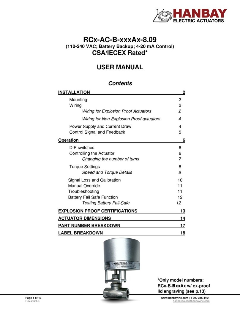
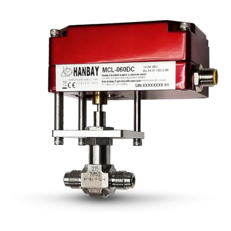
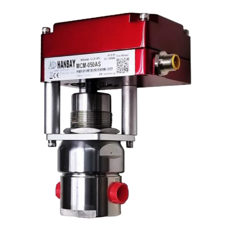
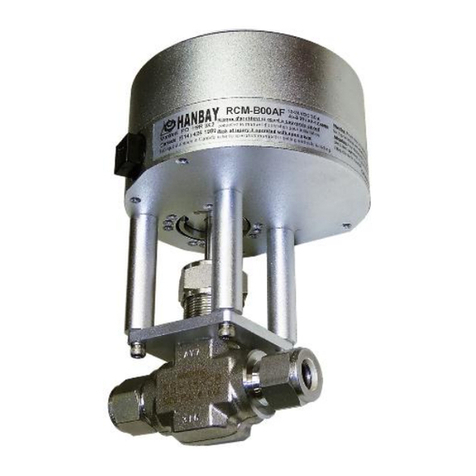
Hanbay RD-AC Series User manual

Page 1 of 13 www.hanbayinc.com | 1 800 315 4461
Rev.2021.9 hanbaysales@hanbayinc.com
*Only model numbers:
RDx-AC-BxxDT w/ ex-proof
lid engraving (p.8)
RDx-AC-xxxDT-10.31
(110-240 VAC; TTL Control)
CSA/IECEX Rated*
USER MANUAL
Contents
INSTALLATION 2
Mounting 2
Wiring 2
Wiring for Explosion Proof Actuators 2
Wiring for Non-Explosion Proof actuators 3
Power Supply and Current Draw 4
Control Signal and Feedback 4
OPERATION 5
DIP Switches 5
Functionality 6
Calibration 7
Manual Override 7
Troubleshooting 8
EXPLOSION PROOF CERTIFICATIONS 8
ACTUATOR DIMENSIONS 9
PART NUMBER BREAKDOWN 11
LABEL BREAKDOWN 13

User Manual RDx-AC-xxxDT-10.31
Page 2 of 13 www.hanbayinc.com | 1 800 315 4461
Rev.2021.9 hanbaysales@hanbayinc.com
INSTALLATION
Mounting
The holes indicated in the image are intended for a mounting
bracket. They are threaded for ¼-20 and are 0.4” deep.
The other two visible holes are threaded 10-32, 0.50” deep, and are
intended to be used to lock the lid in position with screws.
For detailed dimensions see p.9.
Wiring
Wiring for Explosion Proof Actuators
The RCx-AC-BxxAx Explosion-Proof actuator does not come with a pre-installed cable, nor
cable gland. A cable gland that meets site specifications for the appropriate hazardous location
rating is required for installation. The cable gland and the cable for hazardous location should
be installed by qualified personnel in accordance with site and local requirements.
The actuator comes standard with a ½” FNPT thread cable entry. See p.9 for
location of ½” FNPT housing access. A cable with 7 wires is required; it is
recommended to use 3x 16 AWG for wires supplying power and ground, and 4x 20
AWG for wires used for the control and feedback signals.
Standards for cable gland and cable in hazardous locations:
* In explosion-proof models, the FNPT thread is not intended for conduit connection. Cable gland only.
Compliance Standards
Required to be Met
Cable Types Permitted in
Class I Division 1
Hazardous Locations
ANSI / UL 514B, ANSI / UL
1203, ANSI / UL 2225, C22.2
Non-Armored Extra Hard
Usage Cord & TC-ER-HL
ANSI / UL 514B, ANSI / UL
1203, ANSI / UL 2225
Armored IEEE 45 & IEEE
1580 Marine Shipboard Cable
ANSI / UL 514B, ANSI / UL
1203, ANSI / UL 2225
MC-HI, ITC-HL
ANSI / UL 514B, ANSI / UL
1203, C22.2
Teck 90 (Canada Only)

User Manual RDx-AC-xxxDT-10.31
Page 3 of 13 www.hanbayinc.com | 1 800 315 4461
Rev.2021.9 hanbaysales@hanbayinc.com
Once the cable and cable gland are installed, connect the wires to the pins on the terminal block as
indicated here. Note: the cables seen in the image below will not be present in explosion-proof models.
Wiring for Non-Explosion Proof actuators
The actuator comes standard with a pre-installed cable gland and a 10’ cable. Cut the cable to the length
required, then connect according to the following wire color schematic:
Wire color schematic for cable
Pin
Function
6
Already connected to power supply
(connect live wire to loose black cable with crimp connector, see p.4)
5
Already connected to power supply
(connect neutral wire to loose white cable with crimp connector, see p.4)
4
Output TTL2
3
Output TTL1
2
Input TTL2
1
Input TTL1
Colour
Function
Red (1)
Live 110-240 VAC (16 AWG)
Black (2)
Neutral 110-240 VAC (16 AWG)
Blue (3)
Ground (16 AWG)
Green (4)
Output TTL2 (20 AWG)
Grey (5)
Output TTL1 (20 AWG)
Yellow (6)
Signal Input TTL 2 (20 AWG)
Blue (7)
Signal Input TTL 1 (20 AWG)
Terminal
1 2 3 4 5 6

User Manual RDx-AC-xxxDT-10.31
Page 4 of 13 www.hanbayinc.com | 1 800 315 4461
Rev.2021.9 hanbaysales@hanbayinc.com
Power Supply and Current Draw
The RDx-AC-xxxDT actuator may be connected to voltages ranging
within 110-240 VAC.
The current draw will range from minimum 10 mA to maximum 1.5 A while
the actuator is active. When not moving, the actuator draws approx. 5 mA.
AC power is connected to the WHITE & BLACK wires with crimp
connectors (WM18225-DN & WM18230-ND 18-22 AWG).
Ground is connected on the GREEN ground screw, shown below.
Control Signal and Feedback
Locate the correct connection terminals/wires, as shown on the previous page, then connect your input
signal on positions 1 and 2 (blue and yellow wires) as shown below. Feedback, if applicable is connected to
positions 3 and 4 (grey and green wires).
AC Input
Black –Live
White –Neutral
Internal Wires for 24 VDC
(Already Connected)
White +24 VDC
Black 0 VDC
Ground Connection
AC Voltages
AC Gnd common to PWR Gnd
1 2 3 4 5 6
P1
Input #1
TTL I/O Signals
Input #2
Output #2
Output #1
USER SUPPLIED
GND
RL
(max. drive
current 2.5 mA,
optionally up to
1 A)
External
I/O device
supplied by
user
< 1mA
RDx-AC-xxxDT
Internal
Actuator

User Manual RDx-AC-xxxDT-10.31
Page 5 of 13 www.hanbayinc.com | 1 800 315 4461
Rev.2021.9 hanbaysales@hanbayinc.com
In this example DIPs 1, 2, 5 and 12 are on.
OPERATION
DIP Switches
The DIP switches allow you to change the
settings on your actuator. To flip a switch,
gently use a small flat-head screwdriver.
See the table below for DIP switch functionality.
DIP switches 1 and 2 set the actuator position control parameters. High settling speed settings are suitable
for fast positioning of light valves. Longer settling times will allow heavier valves to reach their target
positions; trying to use a fast settling setting on a high torque valve will increase current consumption when
holding position, and cause heating of the motor.
DIP switches 10 and 11 set the actuator torque. These settings are adapted to the valve at the factory. Worn-
in valves may require a higher torque setting after some time. The actuator will use 100% of available torque
to try and reach maximum speed.
DIP 1
DIP 2
Description
Recommended Use
Off
Off
Fastest settling
Use only for low torque valves
Off
On
Medium-fast
Typical setting
On
Off
Medium-slow
Typical setting
On
On
Slowest settling
Use for high torque valves
DIP 10
DIP 11
Torque
description
Approximate
stall current (A)
Approximate stall torque (in-lbs)
RDL
RDM
RDH
RDF
Off
Off
Low
0.75
70
212
430
715
Off
On
Medium-low
1.0
79
236
522
832
On
Off
Medium-high
2.0
81
243
525
949
On
On
High
3.0
82
247
532
1067
Note: Medium-high and high settings require voltage supply minimum values as follows:
-Supply voltage needs to be min 14 VDC for medium-high
-Supply voltage needs to be 16 VDC for high
-When operating above 20 VDC and 66% power, Duty cycle is reduced to 50% - 25%
maximum. At these levels, the electronics produce more heat which must be dissipated
(depending on environmental temperature)

User Manual RDx-AC-xxxDT-10.31
Page 6 of 13 www.hanbayinc.com | 1 800 315 4461
Rev.2021.9 hanbaysales@hanbayinc.com
DIP 3
Reserved for custom function.
DIP 4
Sets direction of offset (offset only required in RDHand RDFmodels).
DIP 5
Sets the highest amount of offset, typically 12°. NOTE: To set maximum offset DIPs 5,6, and 7
will need to be high for a total of 21°. The maximum offset can also be set differently at the
factory (upon customer request).
DIP 6
Sets medium offset, typically 6°.
DIP 7
Sets the lowest amount of offset, typically 3°.
DIP 8
With DIP 8 in the ON position, the actuator will move to 4 positions. When DIP 8 is in the OFF
position, the actuator is limited to three positions. DIP 8 also changes the function of the output
signals. See p.6 for details.
DIP 9
Run / Calibrate
Putting DIP 9 into the off position will disable the actuator positioning control, and the motor will
not move regardless of the input signals.
When DIP 9 is moved back into the on position, the actuator will perform its homing routine,
and then move to the position commanded by the input signals.
DIP 12
DIP 12 sets the direction of rotation
Functionality
The RDx can operate as a 3-position or 4-position actuator. The 4th position is enabled by turning DIP 8 ON.
Note that inputs 1 & 2 (pins 1 & 2) are HIGH by default –a LOW signal must be sent to change the
value. Sending a HIGH signal may be harmful to the internal circuit board.
3-pos Functionality (DIP 8 OFF)
Input #1
(Pin 1)
Input #2
(Pin 2)
Action taken
High
High
Moves to or remains in center position
Low
High
Moves to or remains in right position
High
Low
Moves to or remains in left position
Low
Low
Moves to or remains in right position (Input #2 has
precedence over Input #1)
The feedback from the RDx-xxxDT is as follows:
Output #1
(Pin 3)
Output #2
(Pin 4)
Meaning High = 4.5 VDC Low = 0.8 VDC
High
High
Actuator output is in center position
High
Low
In Right position
Low
High
In Left position
Low
Low
Actuator is moving, or has stalled and given up
trying to reach a requested position.
You may retry to reach any position by cycling
both inputs one after the other. Repeated failures
to reach position will require troubleshooting.
Top View
onto valve or
other
appliance
Centre
Right
(Input #1)
Left
(Input #2)

User Manual RDx-AC-xxxDT-10.31
Page 7 of 13 www.hanbayinc.com | 1 800 315 4461
Rev.2021.9 hanbaysales@hanbayinc.com
4-pos Functionality (DIP 8 ON)
Input #1
(Pin 1)
Input #2
(Pin 2)
Action taken
High
High
Moves to or remains in center position
Low
High
Moves to or remains in right position
High
Low
Moves to or remains in left position
Low
Low
Moves to or remains in back position
The feedback from the RDx-xxxDT is as follows:
Output #1
(Pin 3)
Output #2
(Pin 4)
Meaning High = 4.5 VDC Low = 0.8 VDC
Low
Low
Actuator is at requested position
High
Low
Actuator is moving
Low
High
Actuator has stalled. The stall can be cleared by
making the actuator turn in the other direction.
Direction of rotation and using input 1
To change the direction of rotation on the actuator change the setting on DIP 12 and cycle power to the
actuator. VERY IMPORTANT: Input 1 must always be used if only one input is used to operate the
valve. When the actuator is operated using input 1 an automatic calibration is done every time
the valve is actuated. This does not happen on input 2.
Calibration
The center position calibration routine can be initiated by switching DIP 9 momentarily “off” then “on”. This will
cause the actuator to go through a series of movements to determine the proper center position. This function
is useful if the actuator’s output gear gets manually rotated while the actuator is powered down and can’t
properly realign to the center by itself.
Manual Override
The RDx actuator with manual override can also be certified for hazardous locations (CSA and/or IECEX).
The additional manual override gear case and handle has no effective ignition sources and can therefore be
used in all hazardous locations for which the actuator enclosure is certified for.
Operation of the manual override when power is applied will be difficult as the actuator will try to maintain the
valve in the position it has been commanded to.
Power should be removed if the valve is to be moved manually. If the valve is moved with the
manual override when its power is turned off, it will lose its position, and it will need to be re-
zeroed (as described in the
Calibration section).
Top View
onto valve or
other
appliance
Centre
Right
(Input #1)
Left
(Input #2)
Back

User Manual RDx-AC-xxxDT-10.31
Page 8 of 13 www.hanbayinc.com | 1 800 315 4461
Rev.2021.9 hanbaysales@hanbayinc.com
Troubleshooting
Upon noticing a problem, your first step should almost always be to recalibrate the actuator by toggling DIP 9
while the actuator is powered. This alone can solve basic problems.
If the actuator does not move, try following these steps:
1) Re-calibrate the actuator. This will move the actuator regardless of what signal it is receiving.
2) A sticking valve may be the problem. Remove the valve from the actuator, and re-test the actuator.
3) Remove power. Re-check the wiring and the power/signal apparatus. Power actuator, and re-
calibrate. If the problem persists, please call Hanbay for technical support.
EXPLOSION PROOF CERTIFICATIONS
Actuator model number: RDx-BxxDT
IECEX
Standards & Editions:
IEC 60079-0:2017, 7th Edition
IEC 60079-1:2014, 7th Edition
*Serial number will be engraved on the lid.
CSA
Standards:
Class I, Div 1, Groups B, C, D (T6)
Class II, Groups E, F, G (T6)
CAN/CSA Std. C22.2 No. 0-M91 (R2001)
CSA Std C22.2 No. 25-1966 Locations
CSA Std C22.2 No. 30-M1986 Locations
UL 1203-2006
Lid engraving with CSA & IECEX certifications.

User Manual RDx-AC-xxxDT-10.31
Page 12 of 13 www.hanbayinc.com | 1 800 315 4461
Rev.2021.9 hanbaysales@hanbayinc.com
PART NUMBER BREAKDOWN
Full Hanbay Part Number:
BaseEnclosure
Continuousor Discrete
Gear Train
SpecialOptions
Enclosure Options
Wiring
Thermal Management
PCB
MountingKit
ValvePartNumber
R - - - -
0No Valve or Mounting Kit
1Mounting Kit, Customer Supplies Valve,
does not send valve to Hanbay
2Mounting Kit, Customer Supplies Valve,
CContinuous sends valve to Hanbay
DDiscrete 3Mounting Kit, Hanbay Provides Valve
JExtra Low Torque AB Analog Signal Board
LLow Torque AI Analog Signal Board Isolated Input
MMedium Torque AF Analog Signal Board Isolated with Feedback
HHigh Torque (Add. Gear Stage) DC Continuous TTL Input Board
FHigher Torque (Add. Gear Stage) DT TTL Input Board with Integrated Feedback
AS Modbus Control with Feedback
PT Propane Board, Limit Switches, Thermal Cut Off
0No Option
HInternal Heater
FExternal Fan
0Cable Gland (Specify Cable & length at added cost)
4Custom Dual Guage Cable, 10ft.
5TURCK 5 Position Connector w. 20’ Cable and Plug
6TURCK 6 Position Connector w. 20’ Cable and Plug
7TURCK 5 Position Connector Only
8TURCK 8 Position Connector w. 20’ Cable and Plug (Special)
0Standard Silver Alloy Enclosure
BExplosion-Proof Rated Enclosure
M
Manual Override
SStainless Steel Enclosure
USubmersible
0No Special Options
HT High Temperature Kit
BBattery Backup
GG-Stage Gate Valve (RCM or RCL)
L1 Linear 16 TPI (not for use with RCM)
L2 Linear 8 TPI
MManual Override (When M in Enclosure Option is not usable)
AC 110VAC Power Supply
SSpring Return
RS
Reverse Spring Return
TS Top Stop
BS Bottom Stop
Valve Manufacturers Part # / CU #
R
R-Series

User Manual RDx-AC-xxxDT-10.31
Page 13 of 13 www.hanbayinc.com | 1 800 315 4461
Rev.2021.9 hanbaysales@hanbayinc.com
LABEL BREAKDOWN
Actuator Supply Voltage
12-24 VDC @ 3.0 A or
110-240 VAC @ 1.5 A
Circuit Board Version
Ax-8.09
Dx-10.31
Dx-4.10 (Obsolete since 2019)
Px-10.3
Actuator Part Number
Refer to part number
breakdown for available
options.
Ex-proof Certification
Info on ex-proof ratings
and installation
instructions.
Actuator Serial Number
This serial number is unique
for each individual unit and
is directly tied to your
order/invoice number.
Firmware Version
AF-1.05 MM = Multiturn
AB-1.05 MML = Multiturn Low Torque
AS-1.05 MMUL = Multiturn Extra Low Torque
QM = Quarter turn
QM97 = Quarter turn 97°
DT-2.01
DC-2.01
DT-4.06 (Obsolete since 2019)
M-Dx V2.31
Table of contents
Other Hanbay Controllers manuals

Hanbay
Hanbay MC A 8.09 Series User manual

Hanbay
Hanbay MC DC-2.00 Series User manual

Hanbay
Hanbay RD-DT-10.31 Series User manual

Hanbay
Hanbay MC-B-A-8.09 Series User manual

Hanbay
Hanbay MC-AS-1.05 Series User manual

Hanbay
Hanbay RC Series User manual

Hanbay
Hanbay M Series User manual

Hanbay
Hanbay RC AS-1.05 Series User manual

Hanbay
Hanbay MD DT-10.31 Series User manual
Popular Controllers manuals by other brands

Avipas
Avipas AV-3106 user manual

Siemens
Siemens Simatic S7-1500 manual

Crestron
Crestron 4 Channel Motor Control Module CLX-1MC4 Specification sheet

KBR
KBR Multicomp 2F144-NC-1V1C06RO Operating instructions, technical parameters

ZPA Pecky, a.s.
ZPA Pecky, a.s. MODACT MOA installation instructions

JUMO
JUMO eTron M 100 operating instructions