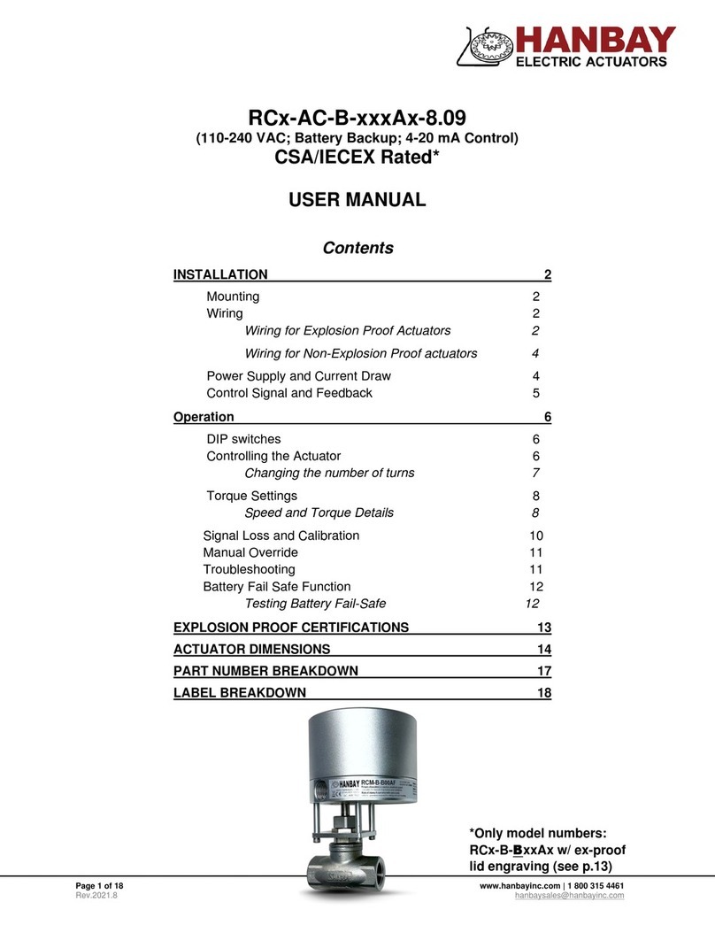
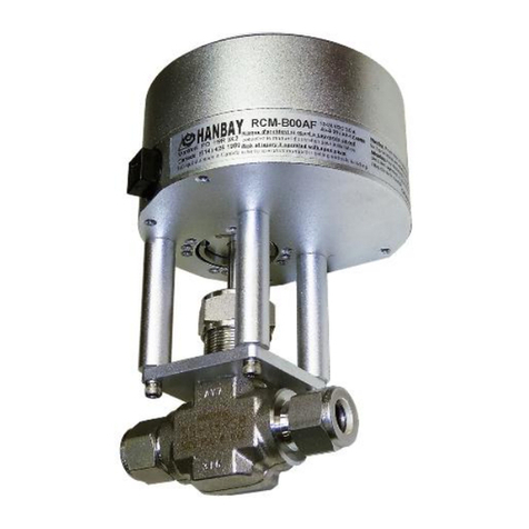
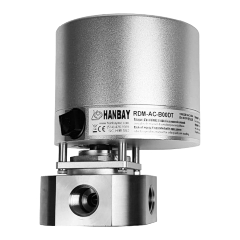
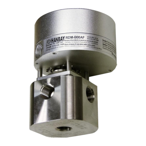
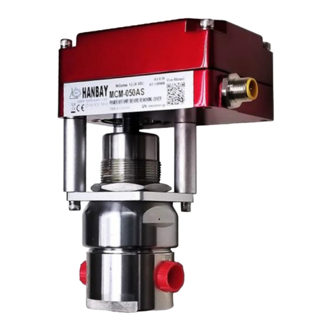
Hanbay MD DT-10.31 Series User manual

HANBAY Inc User Manual MDx-xxxDT-10.31
Page 1 of 8 www.hanbayinc.com
Rev: 2 –July, 2019 1 800 315 4461
hanbaysales@hanbayinc.com
MDx-xxxDT-10.31
Contents
Installation pg. 1-3
Mounting pg 1
Wiring pg 2
Connecting power and signal pg 2-3
Operation pg. 3-5
DIP Switch settings pg 3-4
Functionality pg 4
Torque Settings pg 5
Setting the type of actuator pg 6
Calibration pg 6
Troubleshooting pg 6
Appendix pg. 6-7
Dimensions pg 7
Cable Installation pg 7
Part Number Breakdown pg. 8
Installation
Mounting:
Usually, the actuator has to be mounted and supported as
shown in the picture to the left.
Exceptionally, and only if the application is vibration free and
the tubing is minimum ¼” dia. stainless, the actuator may be
suspended on the tubing itself.
Mounting
Bracket
Attachment Screws
8-32 x 1/2”
User’s mounting
surface
Valve fluid
connections
Cable
Entry

HANBAY Inc User Manual MDx-xxxDT-10.31
Page 2 of 8 www.hanbayinc.com
Rev: 2 –July, 2019 1 800 315 4461
hanbaysales@hanbayinc.com
Wiring:
The actuator comes standard with a Turck 6 position connector and a 20’ cable with plug. Cut the cable to the
length required and then connect according to the following wire color schematic:
Wire color schematic for “Turck6”cable:
Otherwise, if the Turck cable is not included in your actuator, see pg.8 for more detailed wiring instructions.
Pin
Colour
Function
6
White ->
+24VDC
5
Black ->
Power Gnd.
4
Pink ->
Output TT2
3
Grey ->
Output TT1
2
Blue ->
Signal Input TT2
1
Brown ->
Signal Input TT1
Connect the power:
The MDx-xxxDT may be connected to voltages ranging from 12 –24 VDC
The power consumption will range from max. 3.0A to approx. min. 100mA
when the actuator is active. When not moving, the actuator draws around
30mA.
Terminal
123456

HANBAY Inc User Manual MDx-xxxDT-10.31
Page 3 of 8 www.hanbayinc.com
Rev: 2 –July, 2019 1 800 315 4461
hanbaysales@hanbayinc.com
Operation
DIP switches:
The DIP switches allow you to change the
settings on your actuator. To flip a switch,
gently use a small flat-head screwdriver.
See chart below for DIP switch functionality.
Switches 1 and 2 set the actuator position control parameters. High settling speed settings are suitable for fast
positioning of light valves. Longer settling times will allow heavier valves to reach their target positions; trying to
use a fast settling setting on a high torque valve will increase current consumption when holding position, and
cause heating of the motor.
DIP 1
DIP 2
Off
Off
Fastest settling
Use only for low torque valves
Off
On
Medium-fast
Typical setting
On
Off
Medium-slow
Typical setting
On
On
Slowest settling
Use for high torque valves
Connect the signal:
Locate the correct connection terminals as shown on the previous page then connect
your input signal on pos. 1 and 2 and the output signals on 3 and 4 as shown below.
1 2 3 4 5 6
P1
Input #1
TTL I/O Signals
Input #2
Output #2
Output #1
MDM
Actuator
USER SUPPLIED
GND
GND
2
1
1
2
RL
(max drive
current 2mA)
External
I/O device
supplied by
user < 1mA
MDx
DIP switches. In this example DIPs 1, 2, 6 and 12 are on.

HANBAY Inc User Manual MDx-xxxDT-10.31
Page 4 of 8 www.hanbayinc.com
Rev: 2 –July, 2019 1 800 315 4461
hanbaysales@hanbayinc.com
DIP 3
Reserved for custom function.
DIP 4
Sets direction of offset. (Offset only available in MDHand MDFseries)
DIP 5
Sets the highest amount of offset, typically 12°. NOTE: To set maximum offset DIP’s 5,6 and 7 will
need to be high for a total of 21°. The max. offset can also be set differently upon customer request.
DIP 6
Sets medium offset, typically 6°.
DIP 7
Sets the lowest amount of offset, typically 3°.
DIP 8
With DIP switch 8 in the ON position, the actuator will move to 4 positions. When switch 8 is off, the
actuator is limited to three positions. Switch 8 also changes the function of the output signals.
DIP 9
Run / Calibrate
Putting DIP switch 9 into the off position will disable the actuator positioning control, and the motor
will not move regardless of the input signals.
When DIP 9 is moved back into the on position, the actuator will perform its homing routine, and then
move to the position commanded by the input signals.
DIP 10
DIP 11
Description
Approximate stall current
Off
Off
Low torque 16%
0.75A
Off
On
Medium-low 33%
1A
On
Off
Medium-high 66%
2A
On
On
High torque 100%
3A
Approximate stall torque
DIP 10
DIP 11
MDL
MDM
MDH
MDF
Off
Off
55 in-lbs.
120 in-lbs.
405 in-lbs.
756 in-lbs.
Off
On
82 in-lbs.
160 in-lbs.
540 in-lbs.
1008 in-lbs.
On
Off
88 in-lbs.
180 in-lbs.
608 in-lbs.
1134 in-lbs.
On
On
94 in-lbs.
195 in-lbs.
657 in-lbs.
1241 in-lbs.
DIP 12
DIP 12 sets the direction of rotation
Functionality of the MDx-xxxDT:
The MDx can operate as a 3-position or 4-position actuator. The 4th position is enabled by turning DIP 8 ON.
3-pos Functionality (DIP 8 OFF)
Input#1
(Pin 1)
Input#2
(Pin 2)
Action taken
High
High
Moves to or remains in center position
Low
High
Moves to or remains in right position
High
Low
Moves to or remains in left position
Low
Low
Moves to or remains in left position (Input#2 has precedence
over Input #1)
The feedback from the MDx-xxxDT is as follows:
Output#1
(Pin 3)
Output#2
(Pin 4)
Meaning High = 4.5vDC Low = 0.8vDC
High
High
Actuator output is in center position
High
Low
In Right position
Low
High
In Left position
Low
Low
Actuator is moving, or has stalled and given up trying to reach
a requested position.
You may retry to reach any position by cycling alternate inputs
and trying the original again. Repeated failures to reach
position will require troubleshooting.
Top View
onto valve or
other
appliance
Center
Right
Left

HANBAY Inc User Manual MDx-xxxDT-10.31
Page 5 of 8 www.hanbayinc.com
Rev: 2 –July, 2019 1 800 315 4461
hanbaysales@hanbayinc.com
4-pos Functionality (Dip 8 ON)
Input#1
(Pin 1)
Input#2
(Pin 2)
Action taken
High
High
Moves to or remains in center position
Low
High
Moves to or remains in right position
High
Low
Moves to or remains in left position
Low
Low
Moves to or remains in back position
The feedback from the MDx-xxxDT is as follows:
Output#1
(Pin 3)
Output#2
(Pin 4)
Meaning High = 4.55vDC Low = 0.8vDC
Low
Low
Actuator is at requested position
High
Low
Actuator is moving
Low
High
Actuator has stalled. The stall can be cleared by making the
actuator turn in the other direction.
Direction of rotation and using Input 1
To change the direction of rotation on the actuator change the setting on Dip12 and power up the actuator again.
VERY IMPORTANT: Input 1 must always be used if only one input is used to operate the valve.
When the actuator is operated using input 1 an automatic calibration is done every time the valve is
actuated. This does not happen on input 2.
Torque Settings:
Effect of power settings and speed settings:
To accommodate different valves and other applications with different torque requirements, the actuator can be
set to apply different torque on the valve stem when in the seating mode. Please see table on pg. 4 to select the
power setting that is right for your application.
The actuator will use 100% of available torque to try and reach maximum speed. Current drawn will be limited
proportionally to the DIP setting applied actuator will automatically slow down and deliver the maximum available
torque for a given “Permanent Power Setting”.
Top View
onto valve or
other
appliance
Center
Back
Right
Left
Note: 66% setting and 100% setting may alter duty cycle:
-When operating above 66% power, Duty cycle is reduced to 50% - 25% maximum. At these
levels, the electronics produce more heat which must be dissipated (depending on environmental
temperature)

HANBAY Inc User Manual MDx-xxxDT-10.31
Page 6 of 8 www.hanbayinc.com
Rev: 2 –July, 2019 1 800 315 4461
hanbaysales@hanbayinc.com
Appendix
Setting the type of actuator
The actuator is configured at the factory to operate with the mechanical assembly based on the amount and ratio of
gears of the actuator. This is not a user selectable option.
Calibration
The center position calibration routine can be initiated by switching DIP 9 momentarily “on” then “off”. This will cause
the actuator to go through a series of movements to determine the proper center position. This function is useful if
the actuators output gear gets manually rotated while the actuator is powered down and can’t properly realign to the
center by itself.
Troubleshooting:
Upon noticing a problem, your first step should almost always be to recalibrate the actuator by switching DIP 9 on
then off, all while the actuator is powered. This alone can solve basic problems. See above for instructions.
If the actuator does not move, try following these steps:
1) Re-calibrate the actuator. This will move the actuator regardless of what signal it is receiving.
2) A sticking valve may be the problem. Remove the valve from the actuator, and re-test the actuator.
3) Remove power. Re-check the wiring and the power/signal apparatus. Power actuator, and re-calibrate.
If the problem persists, please call Hanbay for technical support.
HANBAY Inc User Manual MDx-xxxDT-10.31
Page 7 of 8 www.hanbayinc.com
Rev: 2 –July, 2019 1 800 315 4461
hanbaysales@hanbayinc.com
Main Dimensions
Actuator connection cable:
Select a connection cable with 6 leads.
The liquid tight strain relief on the base of the actuator is designed to accommodate a cable of
O.D. 2.5 - 6.5mm (0.10 - 0.26in). Be sure to not use a cable with an OD that is no bigger than this!
MDM-xxxDT models
MDH-xxxDT models
1.-Remove the
liquid tight fitting
from the actuator
casing and insert
the cable into it.
4.-Carefully insert the cable into the
actuator base. Mind the red motor cable
and its plug into the board. Moving the
plug out of its fully inserted position may
cause malfunction of the actuator.
5.-Put the liquid tight
fitting back and tighten
(lightly with tool).
7.-Connect wires
according to your
application
(see pg 2).
2.-The cable has to
be stripped of its
jacket for 2 inches
(50mm) and the wires
need 1/8” (3mm)
stripped ends.
3.-Bend the
wires so that
insertion
becomes easy.
6.-Hand tighten the
liquid tight fitting to
establish seal.
8.-Mount actuator
cover and tighten 4
screws.
1
2
5
4
3
8
7
6
Table of contents
Other Hanbay Controllers manuals

Hanbay
Hanbay RC AS-1.05 Series User manual

Hanbay
Hanbay RC Series User manual

Hanbay
Hanbay MC A 8.09 Series User manual

Hanbay
Hanbay MC-B-A-8.09 Series User manual

Hanbay
Hanbay RD-DT-10.31 Series User manual

Hanbay
Hanbay MC DC-2.00 Series User manual

Hanbay
Hanbay M Series User manual

Hanbay
Hanbay RD-AC Series User manual

Hanbay
Hanbay MC-AS-1.05 Series User manual
Popular Controllers manuals by other brands

Danfoss
Danfoss AME 55QM operating guide

cashco
cashco 1164 Installation, operation & maintenance manual

KE2
KE2 AdaptiveControl quick start guide

Mitsubishi
Mitsubishi Q64TCRT user manual

Daikin
Daikin homecontrols EKRSIBDI1V3 Installation and operation manual

rotork
rotork Profibus Modbus Module Mk2 installation manual