Hanover 9820511 User manual
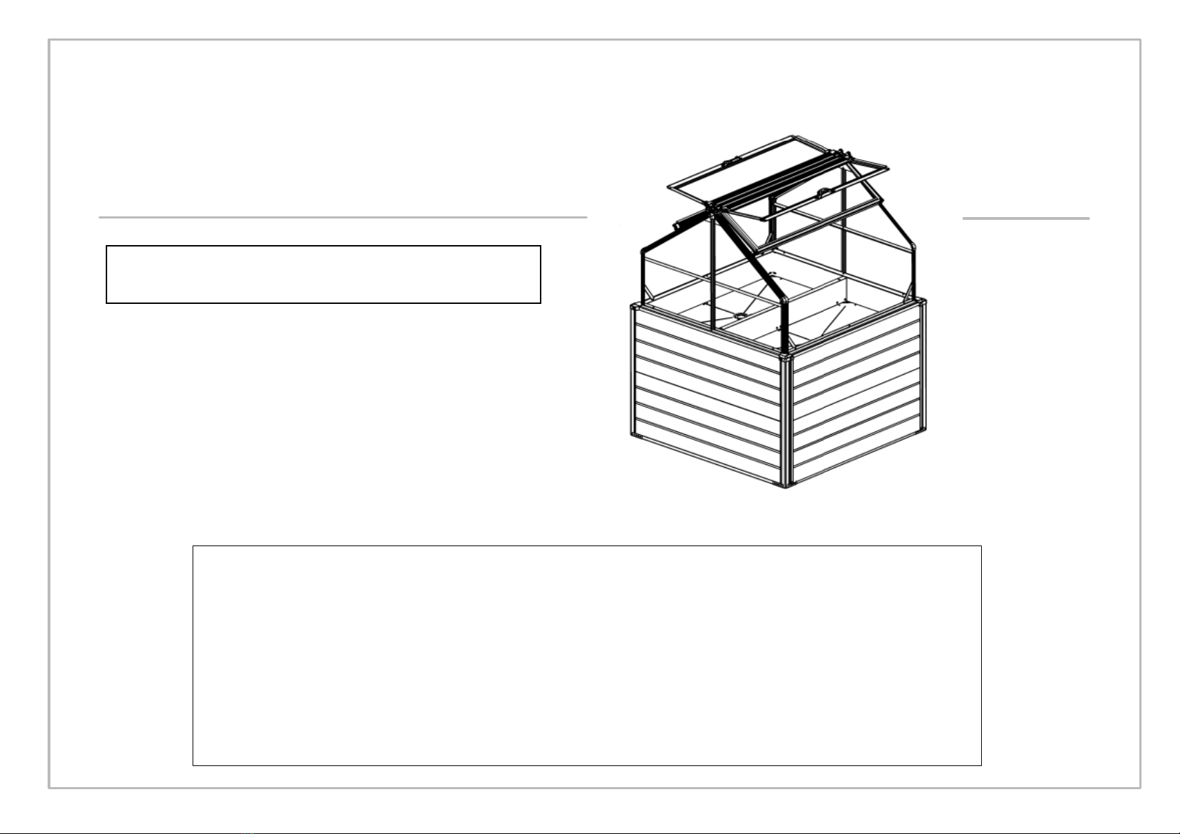
You must read these instructions carefully before you start assembly.
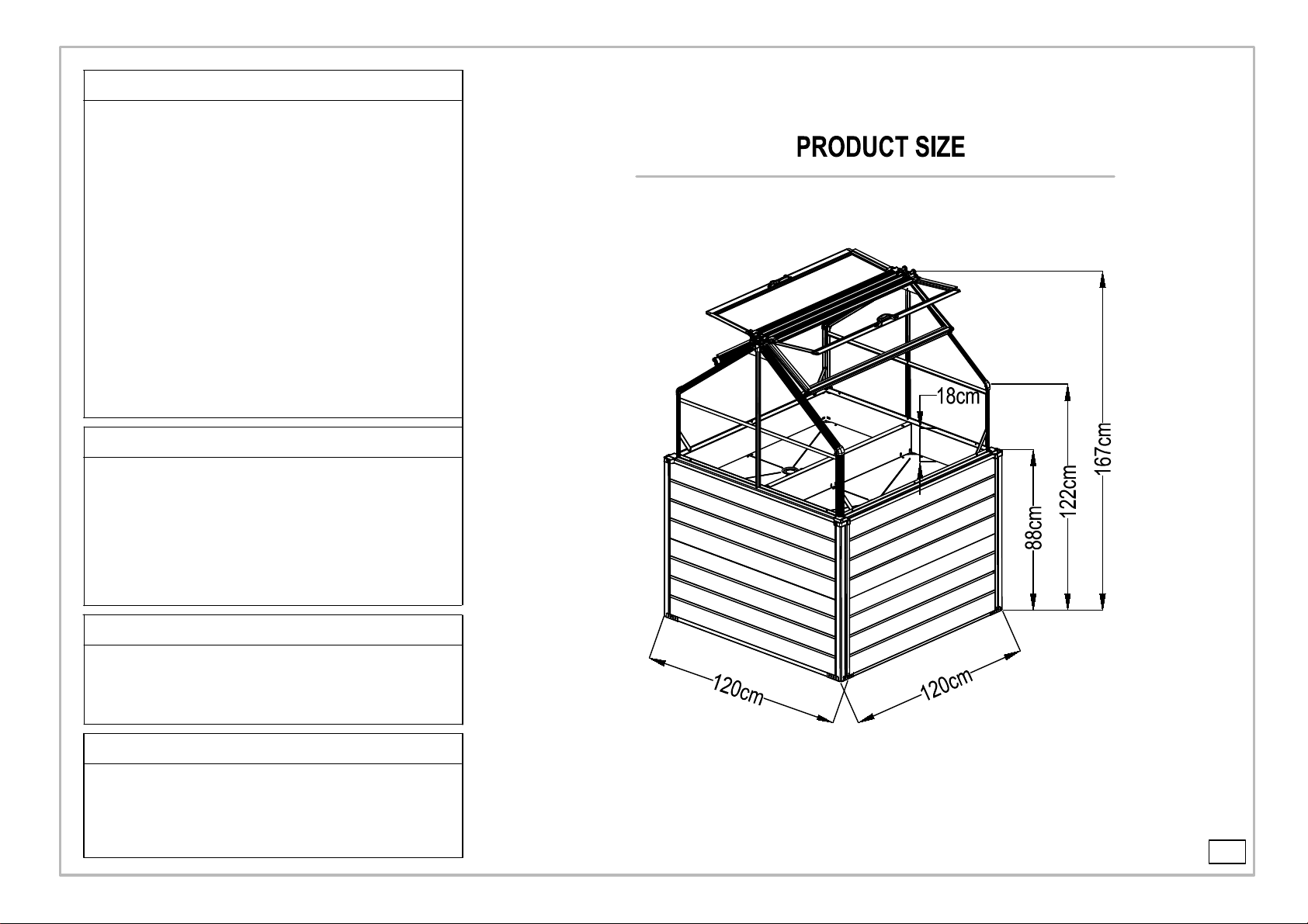
Overall Size/inch: L47"x W47"x H66.5"
Overall Size/cm: L120 x W120 x H169
9820511
Assembly Instruction
the assembly of the whole product.
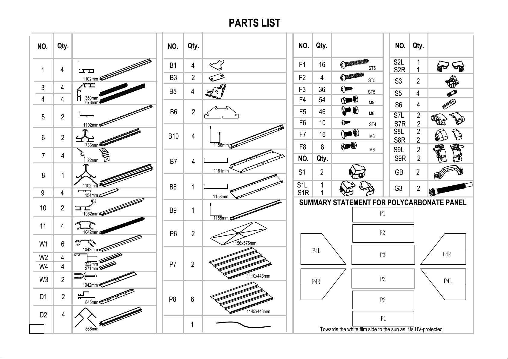
quantity as mentioned in the list.
Do not tighten the steps until completing on
IMPORTANT
Please ensure that you find all parts in the correct type and
Please carry out the steps according to the instructions.
Keep the instruction manuals in a safe place for future reference.
Balcony Mini-Greenhouse
IMPORTANT
Ifyouhaveanyproblemswiththisproduct,please
DONOTRETURNTHISITEM
TotheRetailer/Storefromwhereyoupurchasedtheproduct.
Pleaseemailusanytimewiththenatureoftheproblemat:
ContactUs@Hanover‐Products.com
Pleaseinclude:
Picturesoftheissue(s)andreceipt(ifavailable)
NameandaddressofthePurchaser
Nameofretailer
OrcallourCustomerServiceteambetween9:00AMand5:00PMEasternTime,
MondaythroughFridayat:
1‐877‐397‐5144
orvisitourwebsiteat:
www.Hanover‐Products.com
Toexpediteanyfuturewarrantyclaims,pleaseretainyourreceiptforfutureuse.
Foradditionalon‐linesupportonassembly,troubleshootingandcare&maintenanceofyouroutdoor
product,pleasevisitourwebsiteat:www.Hanover‐Products.com.
8/1/2019
47"
47"
7"
65.7"
48"
34.6"
Work gloves, Spirit level, Lubricant, rubber mallet,0.08" metal drill bit.
Silicone sealant, bradawl, crosshead screwdriver, step ladder,Tape.
risen with cool clean water.
Hot items such as recently used grills, blowtorches etc. can not be stored
Do not attempt to assemble this greenhouse when you feel tired , or have taken
Dispose of all plastic bags safely-keep them out of reach of little children.
SAFETY ADVICE
We strongly recommend the use of work gloves during assembly.
Do not attempt to assemble the greenhouse in windy or wet conditions,
Do not touch overhead power cables with the aluminum profiles.
Always wear shoes and safety goggles when working with extruded
aluminum.
The greenhouse must be positioned and fixed on a flat level surface.
Do not lean against or push the greenhouse during construction.
Keep children away from the assemble area.
Do not position your greenhouse in an area exposed to excessive wind.
drugs or alcohol or if you are prone to dizzy spells.
If using a step ladder or power tools ensure that you follow the
manufactures safety advice.
in the greenhouse.
Ensure there are no hidden pipes or cables in the ground before inserting
the pegs.
GENERAL ADVICE
This is a multi-part assembly, Allow at least 60 minutes for assembly.
Selecting a site-choose a sunny level position away from overhanging trees.
If you are fixing your greenhouse directly to a solid concrete foundation use
the pre drilled holes in the metal base supplied.
The component parts should be checked and laid out close at hand.
Keep all small parts(screws etc)in a bowl so they do not get lost.
Note that the door is hinged on the right hand side and therefore opens to
the right. Keep roof clear of snow and leaves.
CARE & MAINTENANCE
When your greenhouse needs a clean, use a mild detergent solution and
Do NOT use acetone, abrasive cleaners or other special detergents to clean
the clear panels.
TOOLS & EQUIPMENT REQUIRED
.
-3-
29.7"
S10
43.3"
13.8"
26.5"
43.3"
43.3"
41.8"
41"
41"
12.7"
10.7"
41"
33.2"
34"
45.6"
45.6"
45.6"
45.7"
43.7"
45"
45.5"
-4-
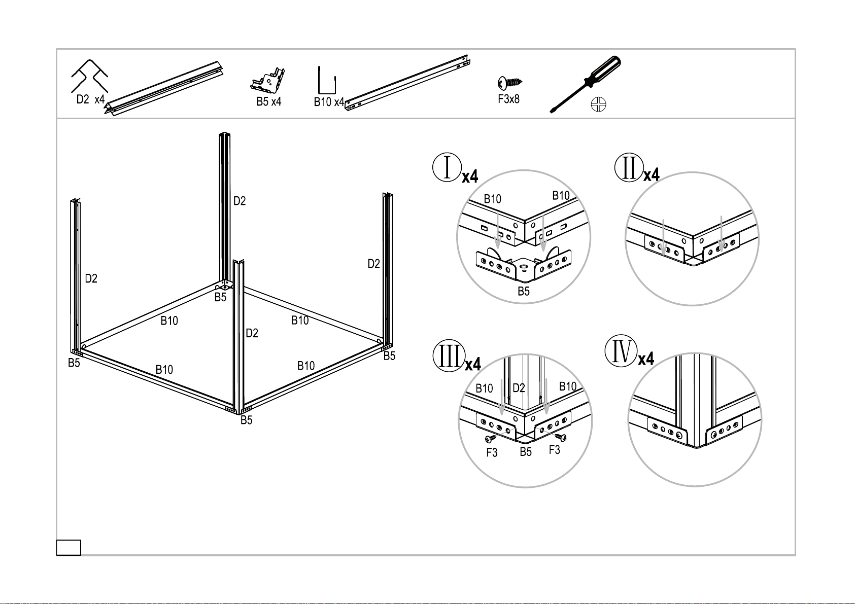
fix B5 anchors onto B10 and D2 by F3 screws.
Repeat the step to complete anchor installation for other 3 corners.
Attach the anchor B5 to the corner of base B10.
Make sure all holes are all in alignment and then
Base and Frame Assembly
Anchor Installation
-5-

Bottom of workbench P6 Installation
Attach D2 & B7 with 12pieces F7 screws.
Attach P6 onto B7 with 8 pieces F5 screws.
Align holes for D2 and B7.
Step II:
Panels of platform B7 Installation
Step I:
-6-
Workbench Assembly

Workbench Assembly
-7-
Install the last piece
Attach B9 & P6
Attach B8 & B7
Assemble B9 & B8 with 6pcs F5 screws.
14 pieces total.
with 6pcs F5 screws.
4 pcs F7 screws.
the two frames D2 with
of wall panel B7 and
Don't lock F5 with 2pcs F5 screws.
of all F5 screws,
Finish the mounting
Step 6:
Step 5:
Step 4:
Step 3: Step 2:
P6
Insert and put the
second P6 bottom
panel on B9.
Step 1:
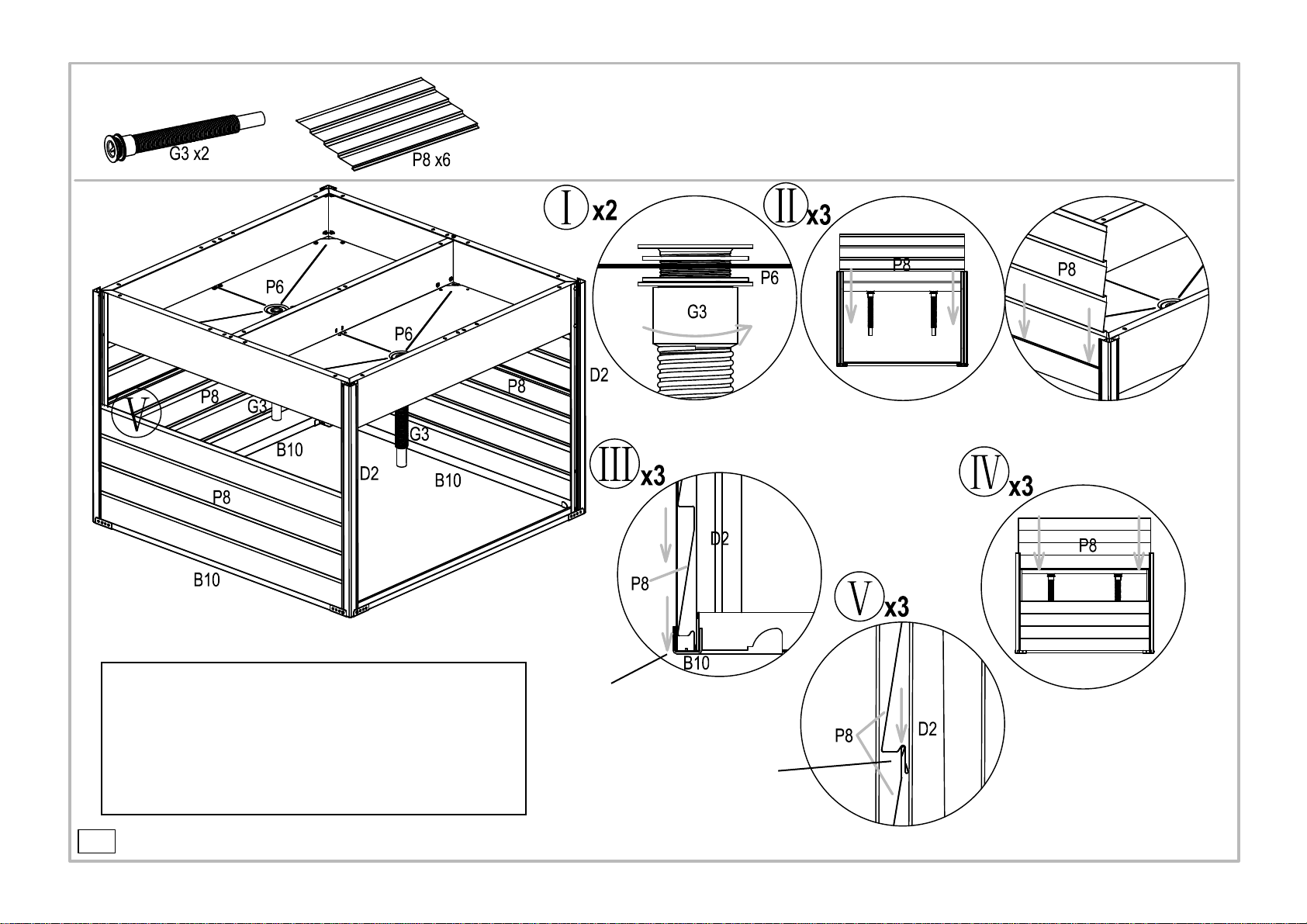
Rotate and tighten the 2 water pipes G3. Insert wall panels P8 into parts D2,
Ensure the bottom edge of
Ensure the bottom edge of
two walls.
Repeat the step 2 for other
Step 5:
Step 3: Step 4:
Step 2:
the top edge of the first P8 panel.
the second P8 panel is against
base B10.
the first P8 panel inserted into
2 pcs P8 panels for each wall.
Side & back wall panels Installation
Water Pipes Installation
Step 1:
-8-
2 pcs P8 panels for each wall.
How to install the water pipe kit?
Step I: Insert the connecting head into the holes in the
middle of P6;
Step II:Attach the water pipe onto connecting head, then
rotate and tighten it via the screw thread on connecting
head.
head and pipe.
G3 water pipe kit is composed by 2 parts,including connecting
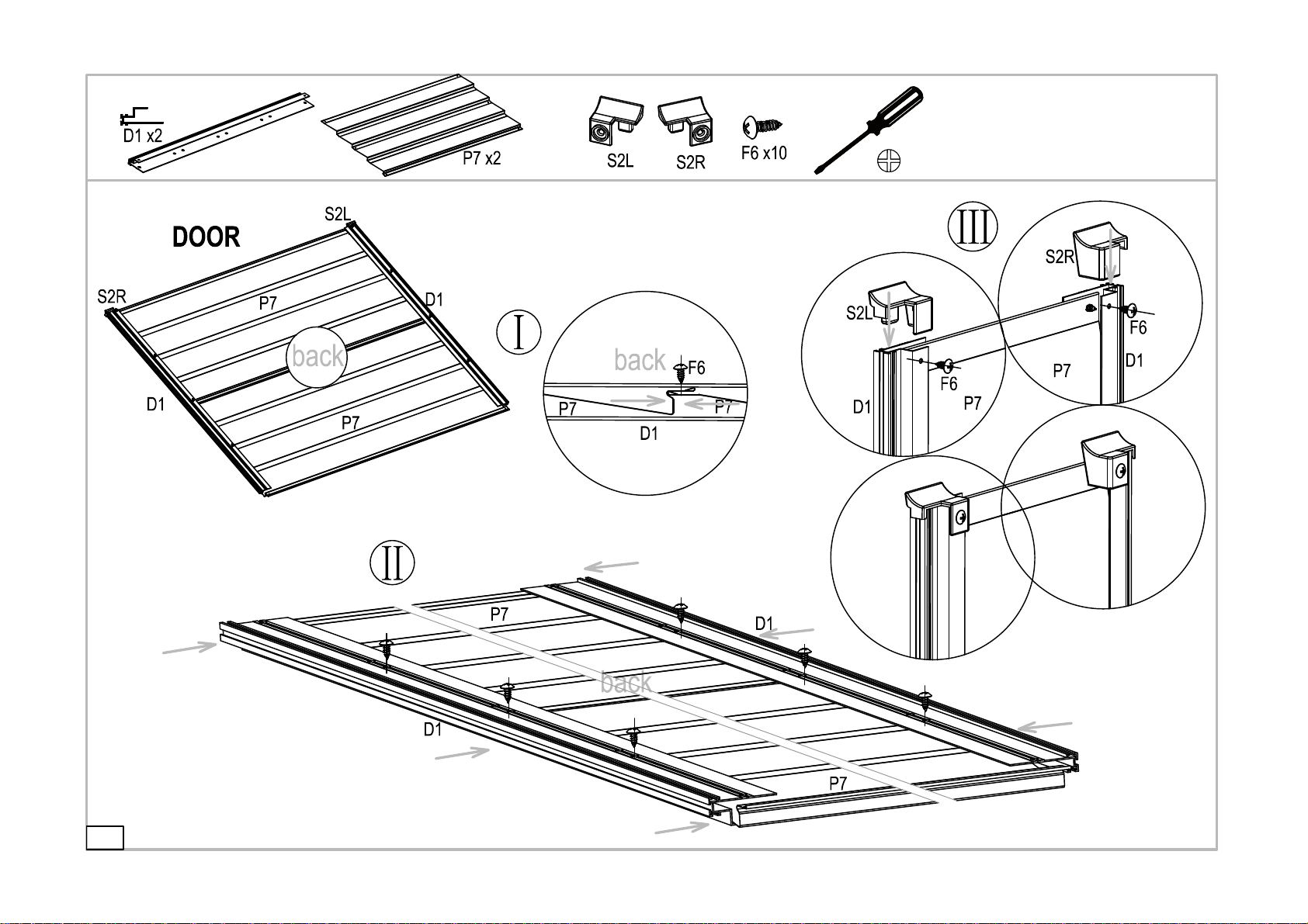
3.Assemble them together in the middle with 2 pieces F6 screws.
fix them with 2 F6 screws.
corner caps S2R,S2L and
Installation for plastic door
Step 3:
Step 2:
1.Put the 2 pieces panels P7 together;
Door Assembly
Step 1:
2.Make sure the two panels are against each other;
Edge frame D1 installation.
F6x6
Fix D1 & P7 with 6 pieces F6 screws,
but don't drive the 2 pieces on the
top where should be left for S2R and
S2L.
-9-
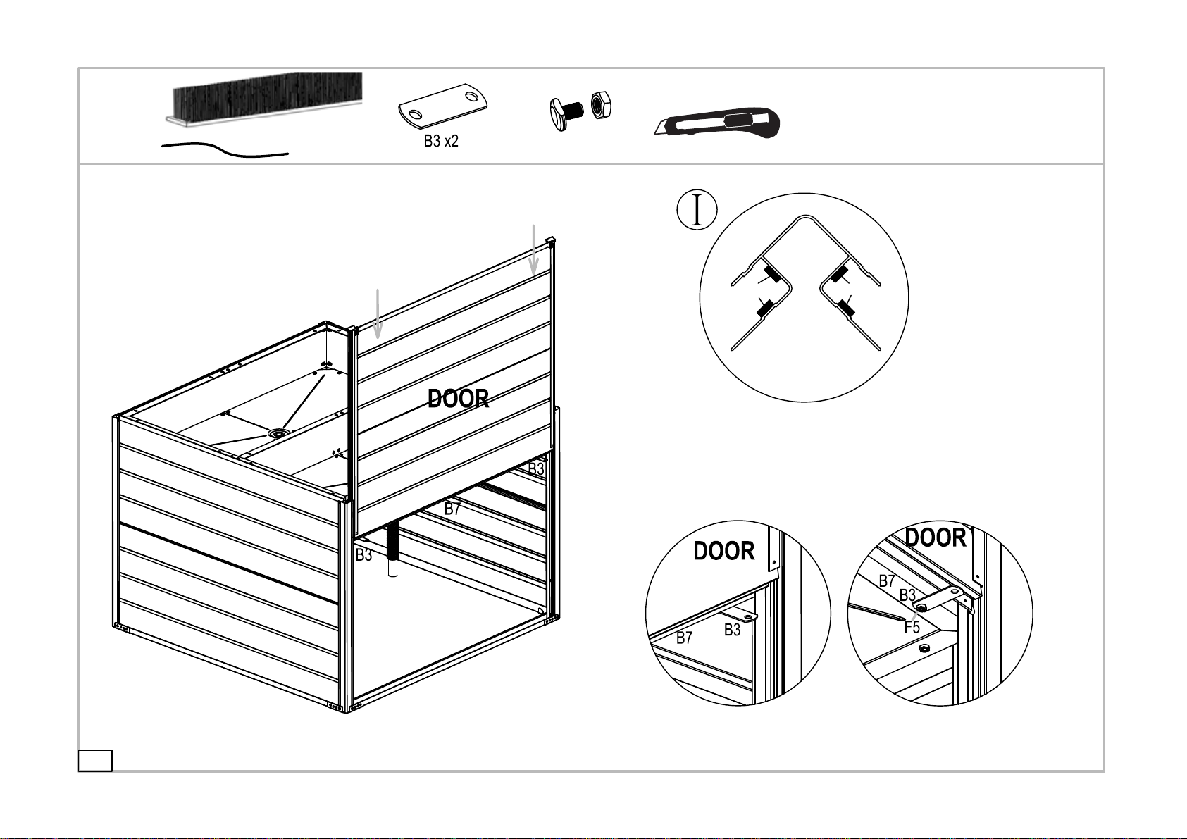
Planform of D2 door
1 hole at each side.
Door Stopper Installation B3
Install B3 beneath the part B7 close to
according to figure I.
Stick the 4 pieces on the inside surfaces of the 2 pieces front D2
Cut the S10 adhesive stripe in
Installation for door sealer S10.
S10
S10 S10
4 pieces,33" long.
There are 2 holes on parts B3.
holes on the bottom of part B7,
-10-
F5 x2
the door with 1 piece F5 screw. There are 2 pre-drilled
D2
D2
frame
and ensure the tail of F5 screws inserting into
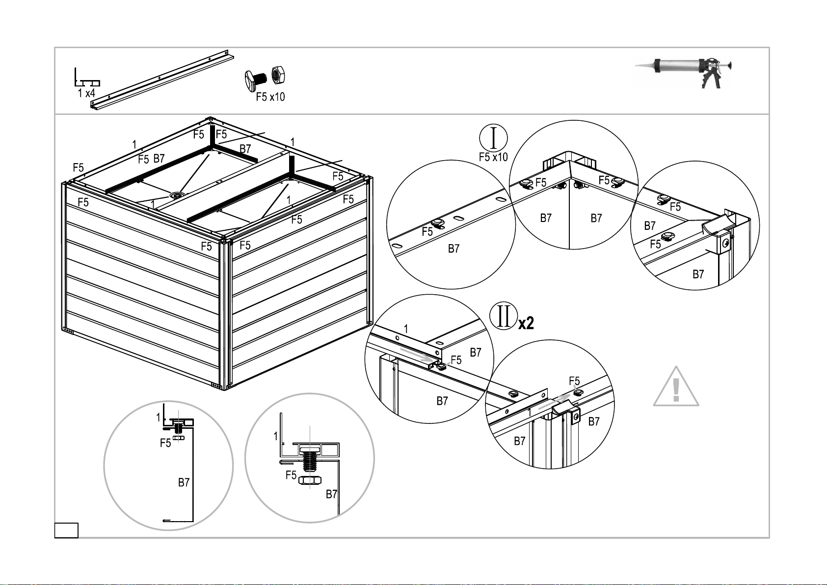
Install the 1# profile by pushing it above B7
Place10 pieces F5 screws
into the pre-drilled holes on the upper
surfaces of B7 and mount the nuts but
Step II:
Silicon
Silicon
Silicon
Installation for base frame of greenhouse.
not fully locked.
the groove of 1# profile.
Step I:
Amplifying detailed figure.
Don't fully tighten
the F5 screws.
-11-
but don't fully tighten them.
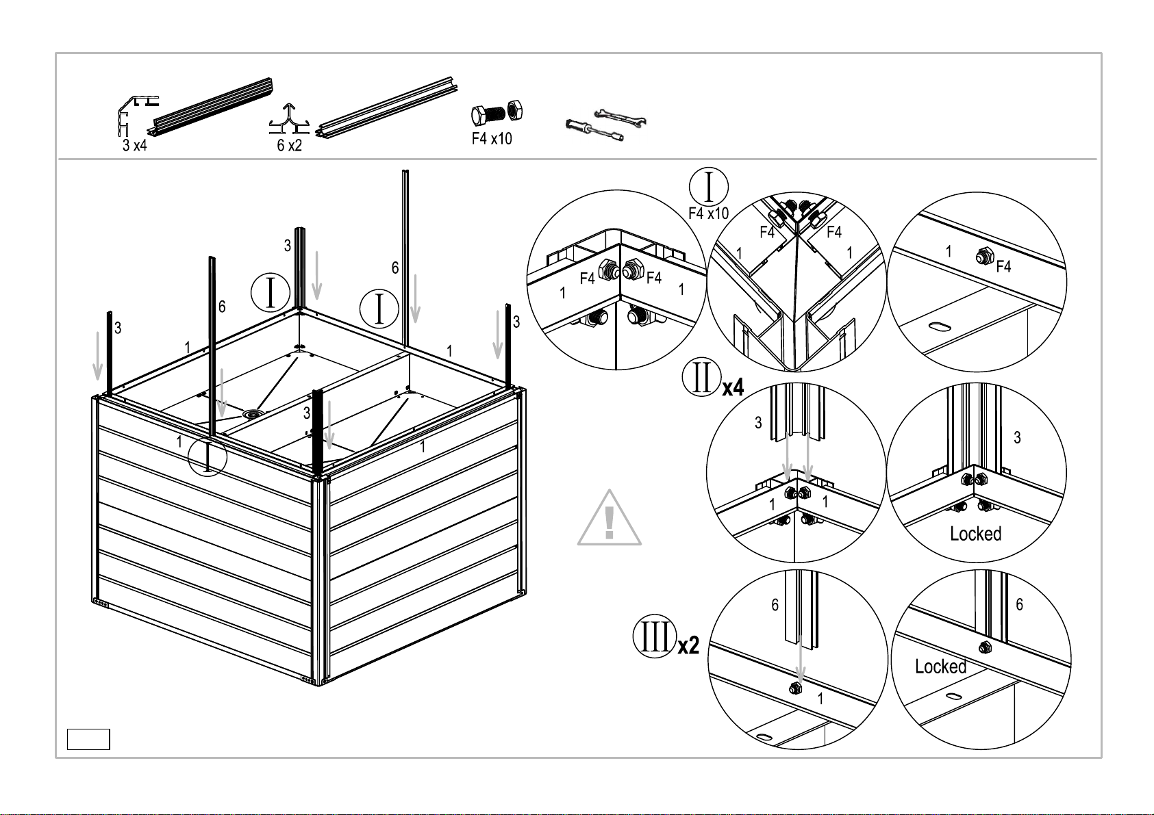
Place 10 pieces F4 screws into the pre-drilled holtes on
into the long frame profiles 6#
the F4 screws.
1# profiles
Step III:
Step II:
into the frame profiles 3#
Installation for the frame of greenhouse
Inserting the tail of F4 screws
of mini greenhouse.
Step I:
Inserting the tail of F4 screws
of mini greenhouse.
Don't fully tighten
-12-

Install part 7#
Pre-place 18 pieces F4 screws
into 7#,9# and 5# parts.
F8 screw. 4 F8 screws needed totally.
Fix the other end of part 9# on to part 1# with
Step VI
Step V
Step IV Reinforcing rib 9# installation
1 piece F4
Step I,II,III
Installation for the beam 7# of greenhouse
Installation for the beam 9# of greenhouse
Installation for the beam 5# of greenhouse
and part 3# together.
The distance between part 1#
and part 5# must be 33cm/13".
Part 5# must be installed inside
of part 6#.
-13-
1
1
1
1

Assemble roof profiles 4# to connectors 7#.
Pre-place part B1 into the
Install panels P4L,P4R into posts 3# and 6#.
Step III:
Step II:
Detailed cutting figure
Step I:
Side PC wall panels P4L & P4L installation
Roof frames 4# installation
Roof frames installation
groove of profile 4#.
-14-

Pre-pance 1 pieces F4 screws
-15-
in each of profile 4.
Pre-place 2 pieces F4 screws
in each of profile 6.
Step IV:
Step III:
Step II: Pre-embedding 2 pieces
Installation for Roof Beam and Fixation Profiles
F4 screws in the holes
at each end of roof beam 8#.
Inserting the roof beam 8#
into frame profiles 4 and
lock the nuts.
Moving the pre-embedded F4 screws
into the pre-punched holes of
end cover B6 and lock the screws.
Step I:
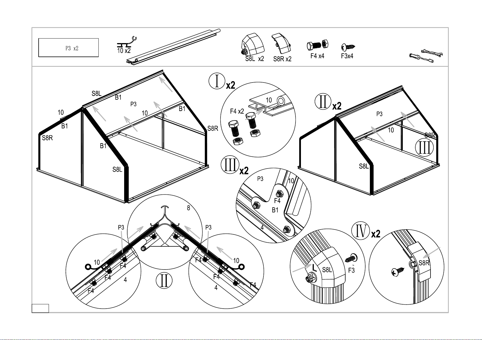
Install corner caps S8L & S8R.
Assemble profile 10 on
Pre-place 2xF4 screws profiles 4 and cover the end edge with
connecting profile 10.
Inserting P3 PC panel into frame
Roof Panel Installation
into the profile 10#.
Part B1 and lock them.
x1
-16-
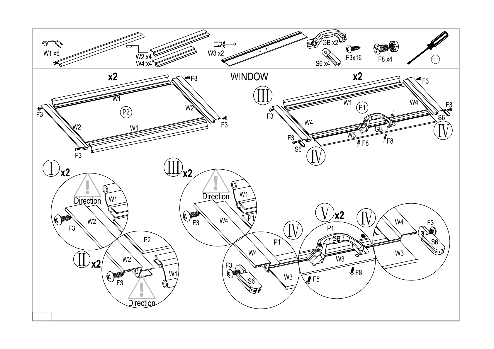
2 pieces F8 screws for one handle,
Assembly for windows Handle Installation
2 handles total.
Middle Window Bottom Window
-17-
Step IV:
Step II:
1.Note the direction of W5;
2.Note the parts P4 & W1
are involved in the groove
of W5.
Step III:
of W4.
1.Note the direction of W4;
2.Note the parts P4 & W1
are involved in the groove

crown of the roof using a screw part F3 on each side.
Installation for rail 11#
Insert rail profile 11# into the
Roof corner plastic caps
S3 installation.
grooves of profile 10#.
-18-
Attach Roof Corner Caps Part S3 to the

Install S5 with 1 piece F2 screws.
Install S9R in same way.
Install S9L with 2 pieces F1 screws.
Install S7R in same way.
Install S7L with 2 pieces F1 screws.
Plastic end caps Installation
-19-
Install S9R in same way.
Install S9L with 2 pieces F1 screws.
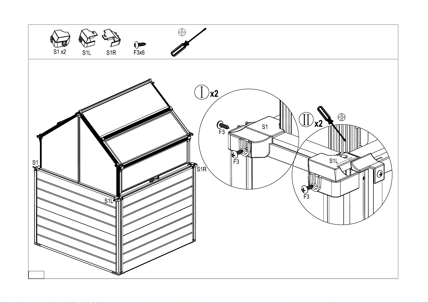
Installing plastic parts S1,S1L and S1R
-20-
Your work is complete, Enjoy!!!
Tighten all Nuts, Bolts, and Screws on the entire Greenhouse
Table of contents
Other Hanover Greenhouse Kit manuals

Hanover
Hanover HANGRNHS6X6-NAT User manual

Hanover
Hanover HANGHMN-1NAT User manual

Hanover
Hanover 9820102-1 User manual

Hanover
Hanover HANGRNHSP8X6-GRN User manual

Hanover
Hanover HANGHGBMN-1WHT User manual

Hanover
Hanover 9820101-1 User manual

Hanover
Hanover HANGHMN-2NAT User manual

Hanover
Hanover HANGHMN-3NAT User manual
Popular Greenhouse Kit manuals by other brands


Vitavia
Vitavia GAIA JUMBO Assembly instructions

Palram
Palram Harmony 6'x4' Assembly instructions

ClearSpan
ClearSpan Storage Master 104598 instruction manual

Sproutwell
Sproutwell GRANGE - 5 Assembly instructions

STC
STC Easy Grow 6x12 Greenhouse Assembly instructions

Growhouse
Growhouse Lean To 6 x 8 Erection and Glazing Instructions


