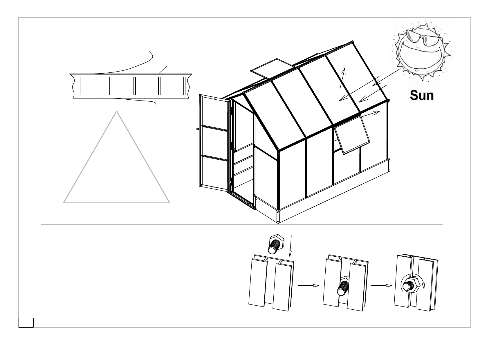
Hanover HANGRNHSP8X6-GRN User manual

You must read these instructions carefully before you start to assemble it.
Overall Size/inch: L98"x W75"x H86"
Overall Size/CM: L250 x W190 x H220
Greenhouse
9820103-1
9820103-2
9820103-3
the assembly of the whole product.
quantity as mentioned in the list.
Do not tighten the steps until completing on
IMPORTANT
Please ensure that you find all parts in the correct type and
Please carry out the steps according to the instructions.
Keep the instruction manuals in a safe place for future reference.
Assembly Instruction

2
IMPORTANT
Ifyouhaveanyproblemswiththisproduct,please
DONOTRETURNTHISITEM
TotheRetailer/Storefromwhereyoupurchasedtheproduct.
Pleaseemailusanytimewiththenatureoftheproblemat:
ContactUs@Hanover‐Products.com
Pleaseinclude:
Picturesoftheissue(s)andreceipt(ifavailable)
NameandaddressofthePurchaser
Nameofretailer
OrcallourCustomerServiceteambetween9:00AMand5:00PMEasternTime,
MondaythroughFridayat:
1‐877‐397‐5144
orvisitourwebsiteat:
www.Hanover‐Products.com
Toexpediteanyfuturewarrantyclaims,pleaseretainyourreceiptforfutureuse.
Foradditionalon‐linesupportonassembly,troubleshootingandcare&maintenanceofyouroutdoor
product,pleasevisitourwebsiteat:www.Hanover‐Products.com.
8/1/2019

3
1.Tape (10feet)
Do NOT use acetone, abrasive cleaners or other special detergent to clean
the panels.
When your greenhouse need cleaning, use a mild detergent solution and
risen with cool clean water.
Dispose of all plastic bags safely. Keep them out of reach of small children.
Always wear shoes and safety goggles when working with extruded
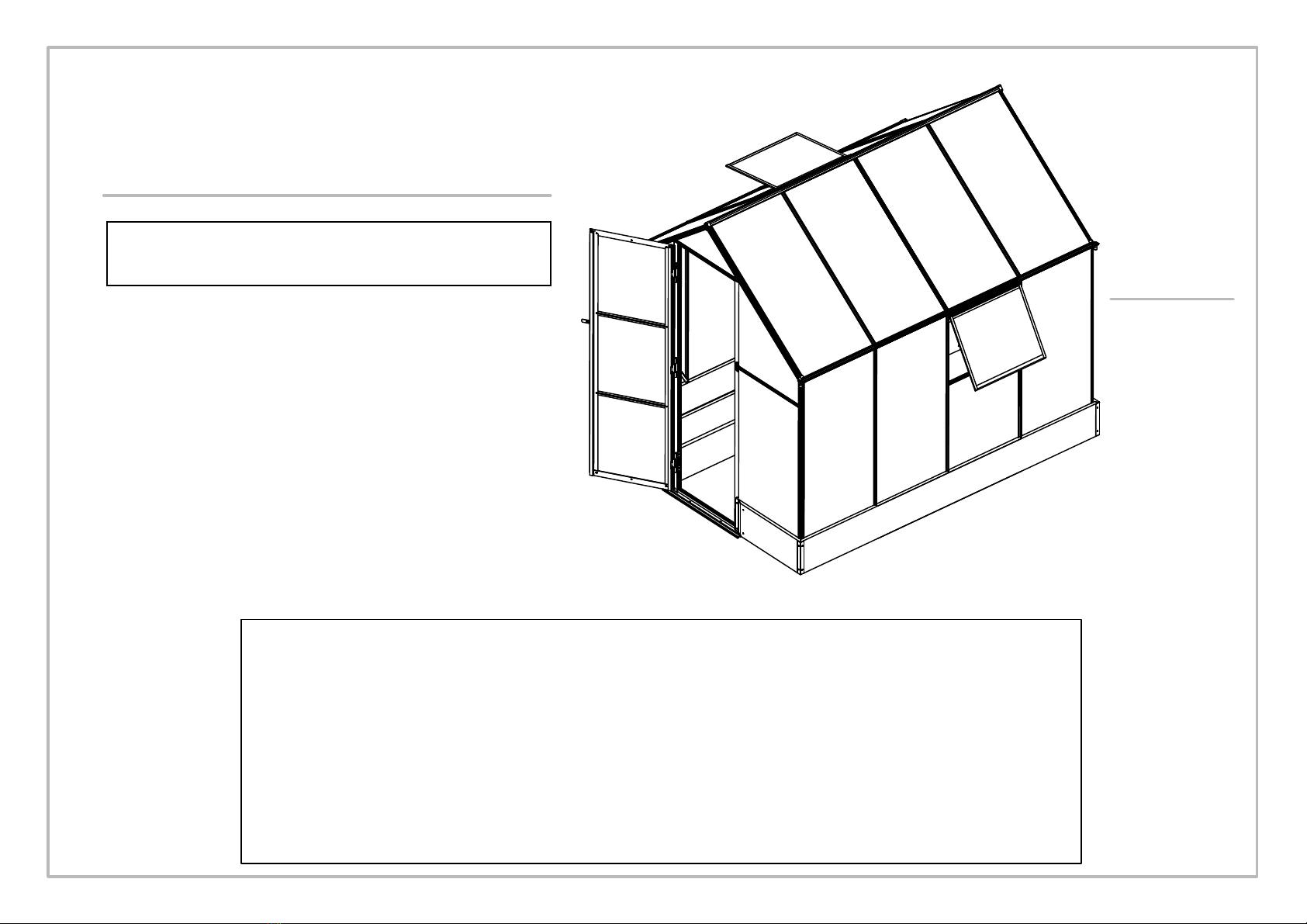
This is a multi-part assembly and needs at least 3-4 hours for assembly.
!
SAFETY ADVICE
We strongly recommend the use of work gloves during assembly.
Do not attempt to assemble the greenhouse in windy or wet conditions,
Do not touch overhead power cables with the aluminum profiles. aluminum.
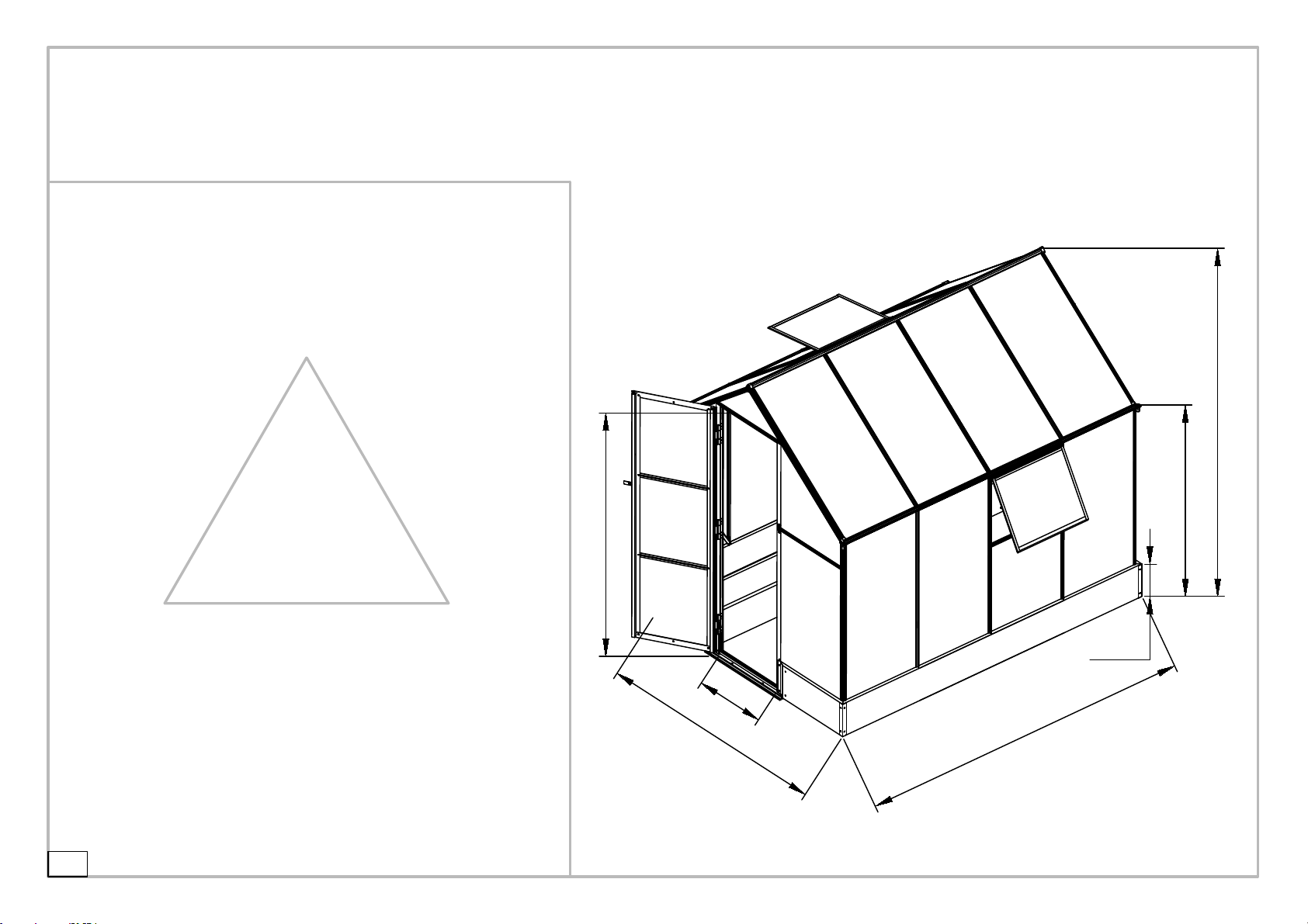
The greenhouse must be positioned and fixed on a flat level surface.
Do not lean against or push the greenhouse during construction.
Keep children away from the assemble area.
Do not position your greenhouse in an area exposed to excessive wind.
Do not attempt to assemble this greenhouse if you are tired ,have taken drugs or
alcohol or if you are prone to dizzy spells.
If using a step ladder or power tools ensure that you follow the manufactures safety
advice.
Ensure there are no hidden pipes or cables in the ground before inserting the pegs.
GENERAL ADVICE
Selecting a site-choose a sunny level position away from overhanging trees.
If you are fixing your greenhouse directly to a solid concrete foundation use the pre
drilled holes in the metal base supplied.
The component parts should be checked and laid out close at hand.
Keep all small parts(screws etc)in a bowl so they do not get lost.
Note that the door is hinged on the right hand side and therefore opens tothe right.
Keep roof clear of snow and leaves.
CARE & MAINTENANCE
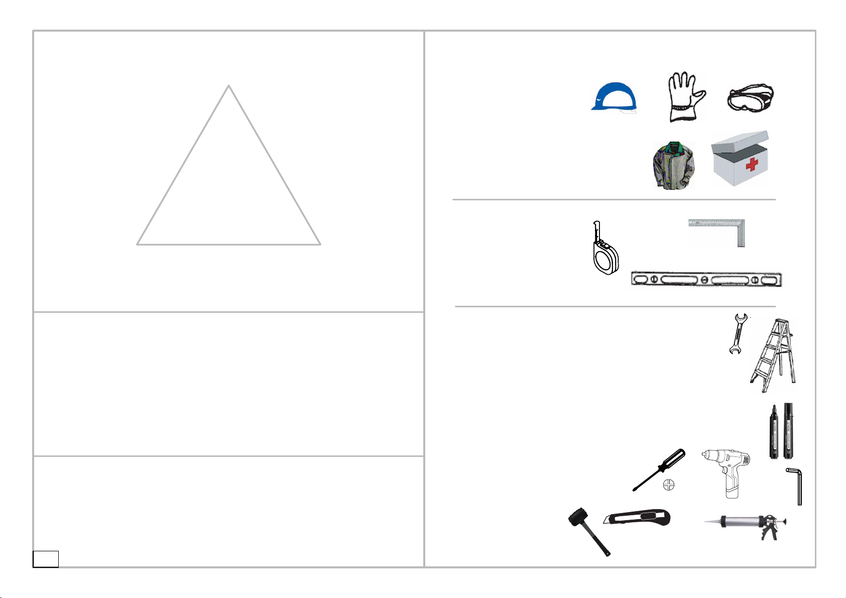
TOOLS &EQUIPMENT REQUIRED
Protective Equipment:
1.Helmet
2.Glove
3.Long Sleeve Cotton Overalls
4.Emergency Medicine Cabinet
5.Eye Shield
Measure (metric):
2.Angle Square
3.Level Meter
Silicon
8.Percussion bit (10mm) (25/64)
7.Marking Pen
6.Wooden Mallet 5mm (13/64) inch hexagon wrench
5.Electric screwdriver +
4.Hexagon wrench 5mm (13/64) inch
1.Triangle Stair 5 feet height
2.Spanner 10mm / (25/64) (Ratchet Wrench is better)
3.Spanner 14mm / (35/64) (Install the expansion screw)
10.Phillips screwdriver
9.Knife
Advised Installation Tools:

4
screws may hurt your eyes.
5. Don't look up if not wearing eye sheld because
9.84"
Find a flat ground which is nearly 2 times bigger than the Green house before installation.
1. 3 people required. One is for measuring & taking
The last one do as assistant and assure the safety.
The second person is responsible for the installation
to ensure the installation dimension.
!
OTHER CAUTIONS
marks
2. High-power electric tools are required, ensure
the normal work of them and highly pay\attention to
electric safety.
3. Be careful when using the kind of blunt tools, like
hammer.
4. Wearing long sleeve cotton overalls,gloves and
helmet during installation and wea safety glasses
when using power tools.
6. No climbing, No standing on the tent to avoid
falling down.
PRODUCT SIZE
250cm
190cm
56cm
220cm
146cm
189cm
25cm
86.6"
57.5"
98.4"
74.4"
74.8"
22"

5
Part list for 9820103 Greenhouse (3-1)
/43.3"
45"
/ 24.9"
/ 29"
/ 1.57"
/ 2.36"
/ 19.4"
NO. Qty.
D1 2
D2 4
1852mm
493mm
5 3
6 6
60mm
40mm
735mm
D7 1
632mm
D5 1
1197mm
1142mm
Front wall and back wall
7 4
16 4
1899mm Upward
9L 1
9R 1
1674mm
Upward
10L 1
10R 1
14 1
22 4
23 4
1838mm
1200mm
1100mm
NO. Qty.
D3 2 550mm
1328mm
NBP1 1
1897mm
NBP2 1
NO. Qty. NO. Qty.
C2 8
B4 4
B5 4
B6 2
L3 1
L3-1 1
L2 1
L5 3
F1 6
F6 6
72.9"
74.7"
47"
65.9"
72.3"
/47.2"
21.6"
52.2"
74.7"

6
Part list for 9820103 Greenhouse (3-2)
96"
95.8"
/ 7.8"
/ 15"
/ 23"
/ 19.7"
/ 23"
/ 22.8"
/ 45"
/ 22.75"
NO. Qty.
Left and right walls and top
NO. Qty.
15 7 578mm
19 6
20 6
1197mm
1142mm
580mm
26 2
2440mm
27L 2
W1 2
W2 4
W3 2
W4 2
588mm
588mm
500mm
380mm
B7 2 200mm
2440mm
2440mm
2433mm
8 2
25 2
17 1
2501mm
NBP5 2
2442mm
PB1 2
NO. Qty. NO. Qty.
B3 2
3A 4
PB03 4
S2 13
S5 2
S6L 2
S6R 2
S8 2
S9 2
F2 8
F3 48
F4 154
F8 2
F9 2
F04 n
F03 n M6
M5
47"
96"
96"
98.5"
96"

7
Part list for 9820103 Greenhouse (3-3)
Summary of polycarbonate panel
P7
PD1
PD1
PD1
P2
P2
P3 P3
P3 P3
P3
P4L P4R
P4L
P4R
P6
P8
P8
P8
P8
P8
P8
P8
P9
P9
P9
P9
P9
P9
P9
P10
P5

8
Pre-placed
The white film side should be toward to the sun as it is UV-protected.
"hexagonal screw"
UV
Place the "hexagonal screw"into the groove,turn
clockwise until it stops turning.
Adjust the "hexagonal screw"by hand and twist so
threads fix it in place.
Place other parts on "hexagonal screw"and
assemble nut .
!
Do not fully-tighten screws

9
Door Frame Assembly - Step 2
PC Panel Installation
Door Assembly
F3 x16
D1 x2
D2 x4 5 x3 D3 x2
D3
D3
D1
F3
F3
F3
F3
F3
D2
D2
D2
D2
180mm
D3
D2
F3
D2
F3
D3
D2F3 PD1
PD1
PD1
PD1
PD1
PD1
D1
F3
F3
F3
F3
F3
F3
F3
180mm
5F3
D1
948mm
F3
Ⅳ
Ⅲ
Ⅱ
Ⅰ
5
5
5
PD1 x3
7"
7"
37.3"
Door Frame Assembly - Step 1 Hinge Installation

10
F2 screws can be screwed easier if using lubricants.
Note the UV surface should be toward the Sun.
Note the direction of parts F8 and
!
W1 x2
W2 x4
W3 x2
W4 x2
S8 x2
S9 x2
F2 x8
F8 x2
F9 x2
WINDOWS x2
W1
W2 W2
F2
F2
W1
W2
F2
P2
!
Note the direction of part No.3
W1
W2
W2
W3
UV
F2
W3
W2
back
W4
W3
F8
F9
S9
S9
S8
F9
Ⅲ
Ⅱ
Ⅰ
Window Installation
Window supporting knob

F3x4pcs
F3x4 pcs
F3x4pcs
11
NBP1
F3 x16
NBP2
NBP1
3A x4
Ⅰ
Silicon
NBP1 NBP1
NBP5
NBP2
NBP1
NBP1
3A
3A
3A
3A
Ⅱ
Ⅲ
Ⅳ
Ⅴ
3A
3A
3A
3A
NBP1 NBP5R
NBP1
NBP5L
NBP5R NBP2
NBP2
NBP5L
NBP5
NBP5
Base Assembly
Connect and reinforce the base panels
with 3 A corner guard part.
F3x4
F3x4 pcs
Install each 3A to each
corner with 4 pieces F3
screw.

12
Lock the screws F4 by hand,
15 x7 B7 x2 F4 x26
F4
C2 x8
Ⅰx5 15
F4
F4
Ⅱx2
15
F4 F4
F4 F4
C2
F4
Ⅲx8
B7
but not fully-tightened.
Pre-place 2 pieces F4 screws in the
groove of 5 pieces part 15#.
Preplace 4 pieces F4 screws for
2 pieces part 5, then install
1 piece part B7 on each part 5#
with the middle 2 pieces F4 screws
preplaced previously.
Pre-fix 1 piece F4 screw onto
the part C2.

13
Frame of backwall Installation
7 x2 F4 x8
14
Ⅰx2
77
NBP2
NBP5R
F4 F4
77
F4
Ⅱ
7
7
14
NBP5R NBP2
NBP5L
Ⅱ
Ⅱ
Ⅰ
Ⅰ
997mm
997mm
F4
14
14
7 7
F4 F4
Ⅲ14
F4
F4
39.2"
39.2"
Back Wall Installation
Pre-place 2 pieces F4 screws in
each groove of part 1.

14
Pre-place 1 piece of F4 screw into
F4 x6
10R
10L
10L
10R
14
F4
F4
10R 10L
F4 F4
Ⅰ
Ⅰ
Ⅱ
10R 10L
NBP2
NBP2
Ⅰx2
Ⅱ
ⅡF4
F4
ⅢⅣx2
14
F4
Ⅳ
Ⅳ
Ⅲ
Ⅲ
F4
Frame Installation
the part 10L/10R.
Insert 1 piece of F4 screw
into the groove of 10R/L,
then fix 10R/10L to part 14
with this piece of screw.

15
Reinforcing Profile No.15 Installation
Don't forget to install the Panel seat S2 before
S2 x3
P3 x3
S2
S2
S2
P3
P3
P3
P3
10L
7
14
15
14
F4
P3
10L
14
15
10R
P3
10R
7
14
15
15
S2 S2
Ⅰx3
P3
7
7
10R
10L
Ⅱ
Ⅱ
Ⅱ
Ⅰ
Ⅰ
Ⅰ
Ⅲ
Ⅲ
Ⅲ
14
Ⅲ
UV
x3
Ⅱ
15
15
15
PC Panels Installation
inserting the PC panels.

16
7 x2 D7 9L
9R
NBP1
NBP1
D7
7
7
9L
9R
Ⅰx2 77
NBP5R
F4 F4
NBP5R
NBP5R
NBP5L
F4 x4
Ⅰ
Ⅰ
F6 x6
NBP1
NBP1
D7
Ⅱ
Ⅱ
Ⅱ
D7
NBP1
9R
9L
D7
D7
NBP1
NBP1
NBP1
Top view
NBP1
D7
9R 9L
F6 x6
Ⅲ
Ⅲ
ⅢⅣ
F6
F6
9L 9R
D7
Front Wall Installation
Corner posts 7# installation

F4 x
Front Wall panels Installation
17
F4
F4
S2 x2
P3 x2
S2
S2
P3
P3
15
9R
9L
7
7
7
79R
9L
C2 C2 C2 C2
F4
F4 F4 F4
Ⅰ
Ⅰ
Ⅰ
F4
F4
Ⅰ
Ⅰ
Ⅰ
Ⅰ
Ⅰ
Ⅰ
15
C2 C2
C2 C2
7
7
9R
9L
15
15
P3 P3
P3 P3
Ⅱ
F4
P3
15
UV
C2
Fix the part 15# with
part C2.
Pre-place 1 piece F4 screw and part C2 into the groove of part 7# accroding to the figure.
Step I:
8

7#.
18
F4 x16
ⅠⅡ
77
77
F4 x3
F4 x3 F4 x3 F4 x3
Ⅲx2
77
88
8
7
7
8
!
F4
F4
8
Ⅰ
Ⅰ
Ⅱ
Ⅱ
8
8
7
7
7
7
Ⅲ
Ⅲ
Ⅲ
Ⅲ
F4 x3
F4 x3
F4 x3
F4 x3
Installation for Eave Profile 8
Pay attention to the
groove in which 2
pieces F4 should be
pre-placed.
Pay attention to the
groove in which 2
pieces F4 should be
pre-placed.
Fix part 8 on to part 7
with the preplaced F4
screws.
Fix part 8 on to part 7
with the preplaced F4
screws.
Fix part 8 on to part 7
with the preplaced F4
screws.
Insert one foot of part 8
into the groove of part

Fix part 19# onto part NBP5L/R
Step III:
Step II:
Fix part 8# onto part 19# with
19
19 x4 F4 x12
19
19
19
19
8
8
F4
Ⅰx4
19
Ⅱx4
F4
F4
F4
F4
19
8
8
19
19
19
8
F4
F4
F4
Ⅲx4
!
Installation for frameof side walls
Pre-place 1 piece F4 screw
into the middle groove of
part 19#. the F4 screw pre-placed in
19# at the first step.
Step I:
the F4 screw pre-placed in
19# at the first step.
7Fix part 8# onto part 7# with 1 piece screw F4.
There are 2 prominent points
on the surface of part 8#.
Insert part 8# into the groove
of part 7# until the prominent
point against part 7#.

20
19 x2 F4 x4
Ⅱx2
19
8
8
19
19
19
8
F4
F4
F4
F4 !
Ⅰx2
19
8
8
19
Install the other eave part 8 in same way
This manual suits for next models
3
Table of contents
Other Hanover Greenhouse Kit manuals

Hanover
Hanover HANGHMN-1NAT User manual

Hanover
Hanover HANGHMN-2NAT User manual

Hanover
Hanover HANGRNHS6X6-NAT User manual

Hanover
Hanover HANGHMN-3NAT User manual

Hanover
Hanover 9820511 User manual

Hanover
Hanover HANGHGBMN-1WHT User manual

Hanover
Hanover 9820102-1 User manual

Hanover
Hanover 9820101-1 User manual
Popular Greenhouse Kit manuals by other brands

Plasson
Plasson Rion Sun Lounge Assembly instructions

Jewett Cameron Companies
Jewett Cameron Companies Weatherguard instructions

ClearSpan
ClearSpan Cedar 8' Wide End Frame Kit manual

Palram
Palram CANOPIA ARIZONA WINGS How to assemble

Palram
Palram HG1005 manual

GardenMeister
GardenMeister GM34304 Assembly instructions