HANSCRAFT TP 700 User manual

USER MANUAL
TP 700

Contents
1 Hottubperformancespecications . . . . . . . . . . . . . . . . . . . . . . . . . . . . . . . . 3
2 Preparation for the installation of the hot tub . . . . . . . . . . . . . . . . . . . . . . . . . 4
2.1 Preparation of the place for installation and connection to electricity . . . . . . . . . . . . . 4
2.2 Preparation for the interior hot tub installation . . . . . . . . . . . . . . . . . . . . . . . . . . . 5
2.3 Preparation for the exterior hot tub installation . . . . . . . . . . . . . . . . . . . . . . . . . . . 5
3 Installation of the hot tub . . . . . . . . . . . . . . . . . . . . . . . . . . . . . . . . . . . . . . . 5
3.1 General information . . . . . . . . . . . . . . . . . . . . . . . . . . . . . . . . . . . . . . . . . . . . . 5
3.2 Filling the hot tub with water . . . . . . . . . . . . . . . . . . . . . . . . . . . . . . . . . . . . . . . 6
3.3 Running the power supply of the hot tub. . . . . . . . . . . . . . . . . . . . . . . . . . . . . . . . 6
3.4 Programming of the hot tub control unit using the control panel . . . . . . . . . . . . . . . . 6
4 Aquatic AV audio system . . . . . . . . . . . . . . . . . . . . . . . . . . . . . . . . . . . . . . . 6
5 Control panel . . . . . . . . . . . . . . . . . . . . . . . . . . . . . . . . . . . . . . . . . . . . . . . 7
5.1 Main displayed data . . . . . . . . . . . . . . . . . . . . . . . . . . . . . . . . . . . . . . . . . . . . . 7
5.2 User interface . . . . . . . . . . . . . . . . . . . . . . . . . . . . . . . . . . . . . . . . . . . . . . . . . 8
5.3 Run spa devices . . . . . . . . . . . . . . . . . . . . . . . . . . . . . . . . . . . . . . . . . . . . . . . . 11
5.4 Spa behavior . . . . . . . . . . . . . . . . . . . . . . . . . . . . . . . . . . . . . . . . . . . . . . . . . . 12
5.5 Settings menu . . . . . . . . . . . . . . . . . . . . . . . . . . . . . . . . . . . . . . . . . . . . . . . . . 13
5.6 Setltercycletimes . . . . . . . . . . . . . . . . . . . . . . . . . . . . . . . . . . . . . . . . . . . . 15
5.7 Set time-of-day . . . . . . . . . . . . . . . . . . . . . . . . . . . . . . . . . . . . . . . . . . . . . . . . 16
5.8 Heat settings . . . . . . . . . . . . . . . . . . . . . . . . . . . . . . . . . . . . . . . . . . . . . . . . . 17
5.8.1 Heat modes . . . . . . . . . . . . . . . . . . . . . . . . . . . . . . . . . . . . . . . . . . . . . . . . . . 17
5.8.2 Heat modes . . . . . . . . . . . . . . . . . . . . . . . . . . . . . . . . . . . . . . . . . . . . . . . . . . 18
5.8.3 Temperature ranges . . . . . . . . . . . . . . . . . . . . . . . . . . . . . . . . . . . . . . . . . . . . . 20
5.8.4 M8 . . . . . . . . . . . . . . . . . . . . . . . . . . . . . . . . . . . . . . . . . . . . . . . . . . . . . . . . 21
5.8.5 Change the set temperature. . . . . . . . . . . . . . . . . . . . . . . . . . . . . . . . . . . . . . . . 22
5.9 Invert display . . . . . . . . . . . . . . . . . . . . . . . . . . . . . . . . . . . . . . . . . . . . . . . . . 23
5.10 Restrict operations. . . . . . . . . . . . . . . . . . . . . . . . . . . . . . . . . . . . . . . . . . . . . . 24
5.11 Diagnostics . . . . . . . . . . . . . . . . . . . . . . . . . . . . . . . . . . . . . . . . . . . . . . . . . . 25
6 Panel messages. . . . . . . . . . . . . . . . . . . . . . . . . . . . . . . . . . . . . . . . . . . . . . 26
6.1 General messages . . . . . . . . . . . . . . . . . . . . . . . . . . . . . . . . . . . . . . . . . . . . . . 26
6.2 Heater-related messages . . . . . . . . . . . . . . . . . . . . . . . . . . . . . . . . . . . . . . . . . . 27
6.3 Sensor-related messages . . . . . . . . . . . . . . . . . . . . . . . . . . . . . . . . . . . . . . . . . . 28
6.4 System-related messages . . . . . . . . . . . . . . . . . . . . . . . . . . . . . . . . . . . . . . . . . 29
6.5 Reminder messages . . . . . . . . . . . . . . . . . . . . . . . . . . . . . . . . . . . . . . . . . . . . . 30
6.6 Miscellaneous messages . . . . . . . . . . . . . . . . . . . . . . . . . . . . . . . . . . . . . . . . . . 31
6.7 Message notes . . . . . . . . . . . . . . . . . . . . . . . . . . . . . . . . . . . . . . . . . . . . . . . . 32
6.8 Fault log. . . . . . . . . . . . . . . . . . . . . . . . . . . . . . . . . . . . . . . . . . . . . . . . . . . . . 33
7 Supplements . . . . . . . . . . . . . . . . . . . . . . . . . . . . . . . . . . . . . . . . . . . . . . . 34
8 Upkeep of the hot tub . . . . . . . . . . . . . . . . . . . . . . . . . . . . . . . . . . . . . . . . . 35
8.1 General information . . . . . . . . . . . . . . . . . . . . . . . . . . . . . . . . . . . . . . . . . . . . . 35
8.2 Removalandcleaningoftheltercartridge . . . . . . . . . . . . . . . . . . . . . . . . . . . . . . 35
8.3 Maintaining the quality of the water in the hot tub . . . . . . . . . . . . . . . . . . . . . . . . . 36
8.4 Replacing the water . . . . . . . . . . . . . . . . . . . . . . . . . . . . . . . . . . . . . . . . . . . . . 37
8.5 Cleaning the outer shell of the hot tub . . . . . . . . . . . . . . . . . . . . . . . . . . . . . . . . . 37
8.6 Hot tub hygiene and disinfection . . . . . . . . . . . . . . . . . . . . . . . . . . . . . . . . . . . . . 37
8.7 Thermo cover . . . . . . . . . . . . . . . . . . . . . . . . . . . . . . . . . . . . . . . . . . . . . . . . . 37
8.8 Upkeep of the thermo cover and upkeep instructions . . . . . . . . . . . . . . . . . . . . . . . . 38
9 Winter and summer time. . . . . . . . . . . . . . . . . . . . . . . . . . . . . . . . . . . . . . . . 38
9.1 Winter time – using the hot tub, all year operation (SLP) . . . . . . . . . . . . . . . . . . . . . . 39
9.2 Summer time . . . . . . . . . . . . . . . . . . . . . . . . . . . . . . . . . . . . . . . . . . . . . . . . . 39
10 Final establishments . . . . . . . . . . . . . . . . . . . . . . . . . . . . . . . . . . . . . . . . . . 39
10.1 Guarantee conditions . . . . . . . . . . . . . . . . . . . . . . . . . . . . . . . . . . . . . . . . . . . . 39
10.2 Safe disposal of the product after the service life . . . . . . . . . . . . . . . . . . . . . . . . . . 39
10.3 Warranty claims and repair services . . . . . . . . . . . . . . . . . . . . . . . . . . . . . . . . . . . 39
11 Repair services chart . . . . . . . . . . . . . . . . . . . . . . . . . . . . . . . . . . . . . . . . . . 40

3
Hot tub performance specifications
1 Hot tub performance specifications
Performance specifications
nominal voltage: three-phase connect. 230/400 V 50 Hz*
maximum work current: 3× 16 A
current surge: up to 3× 25 A
voltage resistance: 1 250 V/min. without puncturing
insulation resistance: >=1MΩ
water resistance: IPX5
electrical shock protection: rstlevel
*The product does not use 400 V phase to phase voltage. It is possible to adjust it to
1× 230 V. When setting to 1× 230 V, it is necessary to observe the cross-section of the
supply wire; namely: CYKY – 3× 10. A circuit breaker and Residual Current protective
Device 32 A, according to the applicable standards of the country where the product is
installed. This setting is necessary to maintain all functions of the tub.
Stress load
heating: 1× 230 V/3 kW/13.6 A
ozone: 1× 230 V/50 Hz /80 mA
blower: 1× 230 V/0.66 kW/ 2.9 A
circulation pump 1/1 + 1/1: 2.2 kW + 2.2 kW + 0.4 kW
overall wattage (depends on the hot tub type):
8.5 kW / h
protection class: I.
lighting: LED 12 V/10 W
maximum output: 20 W
Preparation and electrical connection options – AC three-phase
current 3× 230/400 V/16 A/20 A
Ensure that the hot tub is always connected to a circuit protected by a Residual Current
protective Device with a rated tripping current of 0,03 A. It is necessary to use
For your own safety and the safety of your product, please observe the
following instructions. Read the following information carefully and follow
the user manual exactly when using the hot tub to avoid damaging the product
or the risk of injury. This appliance is intended for use by children 8 years of
age or older with reduced physical, sensory or mental capabilities, or lack of
experience and knowledge, provided they are under supervision or have been
instructed on the use of the product and understand the risks. Children must
not play with the product. Cleaning and maintenance must not be performed by
children without supervision.

4
Preparation for the installation of the hot tub
a Type C or Type D circuit breaker with a rated current of 16 A (motor circuit breaker)
downstream of the Residual Current protective Device.
Recommended Type C circuit breaker
Hot tubs with two massage motors: 3× 16 A/C or D
Hot tubs with three massage motors: 3× 20 A/C or D
!!! THE HOT TUB MUST BE INSTALLED BY AN ELECTRICIAN WITH THE
APPROPRIATE QUALIFICATION ONLY !!!
2 Preparation for the installation of the
hot tub
Check the hot tub first before the installation. Immediately contact the
seller in case any of the parts are broken or missing. Make sure that all the
components correspond to your order
. Check the hot tub before every use.
In case of any damage, do not use the hot tub.
2.1 Preparation of the place for installation and connection to
electricity
The hot tub must be installed on a at, suciently solid base plate, taking into
account the load-bearing capacity of the building. If the hot tub is installed outdoors,
we recommend constructing a concrete monolithic base slab with a minimum strength
(thickness) of 10 cm. It is important to also always select the load-bearing capacity of
the base slab with regard to the dimensions and the weight of the hot tub. Consult
your building supervisor. The weight is specied in the technical description of the
given hot tub. The tubs are prepared by us for an electrical connection of
3× 230 V/400 V~ alternating current. Therefore, use a circuit breaker 3× 16 A/C or D,
alternatively 3× 20 A/C or D and a Residual Current protective Device corresponding
to this connection. Furthermore, it is necessary to have a cable with parameters
corresponding to the rightful regulations for this type of connection. The cable must
also have 4 usable meters at the location of the hot tub, so that it can be pulled
through and connected to the control unit without complications. Do not route the
cable under the hot tub!
NO
YES

5
Preparation/Installation of the hot tubPreparation for the installation of the hot tub
2.2 Preparation for the interior hot tub installation
If the hot tub is installed in an interior space, it is necessary to comply with safety
instructions. The basic safety requirements are mainly non-skid oors and drainage in
the place of the installation in case of a water overow. It is also crucial to keep in mind
that the humidity around the hot tub will rise and can damage surrounding electric ap-
pliances. Therefore we recommend customizing the place of the installation according
to these conditions. The hot tub should be accessible from all sides for future repair
services. If it is not suciently accessible during the guarantee period, the owner has
a duty to ensure the access.
2.3 Preparation for the exterior hot tub installation
If the hot tub is installed in an exterior space, it is necessary to comply with safety
instructions. The basic safety requirements are mainly non-skid oors and water drain-
age in case of a rainfall or water overow from the hot tub. Therefore we recommend
customizing the place of the installation according to these conditions.
3 Installation of the hot tub
Warning: connection to electricity must be done according to norms valid in
CzechRepublicČSN332000-7-701
3.1 General information
We strongly recommend you to hire professionally trained and qualied technicians
for the process of installation. If you decide to install the hot tub by yourself, please
abide by the following instructions.
a) Carefully remove all the packaging material from the hot tub and position the hot
tub on a beforehand selected place of installation.
b) Demount the front panel on the side of the hot tub control panel. Demount the
upper cover of an electrical wiring under which you can nd a residual current
device, a ground fault circuit interruptor (if it is part of the hot tub equipment)
and a ground staple. The connection itself must be done by a person with an
expert qualication.
c) Every hot tub is tested in real life conditions during the production process,
therefore there is a possibility some technical parts of the hot tub have remained
slightly dirty. We recommend you to clean the surface of the hot tub using a
suitable method; lukewarm water works best for this purpose. Clean the surface
using a soft cloth only. Don't use any rough abrasive means and cloths which could
permanently damage the surface of the hot tub. If you decide to use a generic
cleaning detergent, it cannot be aggressive towards the hot tub surface.

6
Installation of the hot tub/Audio system Aquatic
3.2 Filling the hot tub with water
Fill the hot tub with a sucient amount of water. The level of water in the hot tub
cannot ever fall under the skimmer level. If you notice a water leak, stop the water
until the defect is xed. Hot tubs do not possess the technology for water-softening
and hard water can be damaging to them. The damages caused by poor handling and
upkeep are not covered by the guarantee.
a) Fill the hot tub through a skimmer to prevent an over aeration of the circulation
pumps.
b) Do not ll the hot tub with water of temperature over 104 °F.
c) Once the water reaches the desired level, put the cartridge lter inside the
skimmer. Tilt the lter during the installation to prevent air bubbles. Only after
removing the air from the lter, install the lter into place.
3.3 Running the power supply of the hot tub
If the hot tub is connected by a moving supply cable, this cable cannot come in con-
tact with sharp objects or be exposed to external forces. Therefore we recommend
putting the supply cable inside a protective case. Turn on a residual current device
intended for a hot tub.
3.4 Programming of the hot tub control unit using the control
panel
Now you can start the programming of the hot tub. The process is described in the
chapter “Control panel”. After you are nish the programming, cover the hot tub with
a thermo cover and let the water temperature to stabilize. Check the water level
inside the hot tub regularly.
4 Aquatic AV audio system
Aquatic AV audio system AQUATIC/MY MUSIC (relevant only for hot tubs equipped
with the system)
If you want to play music from an external device, it is necessary to pair the device
with the hot tub rst (phone, tablet, computer). Turn on the bluetooth system on your
external device and search for the AQUATIC device. The connection is not restricted by
a code and only one connection can be active at a time. You can play music immediately
after the devices are successfully paired. You can control all the functions of the audio
system on your connected external device.
7
Control panel
Installation of the hot tub/Audio system Aquatic
5 Control panel (BALBOA TP 700)
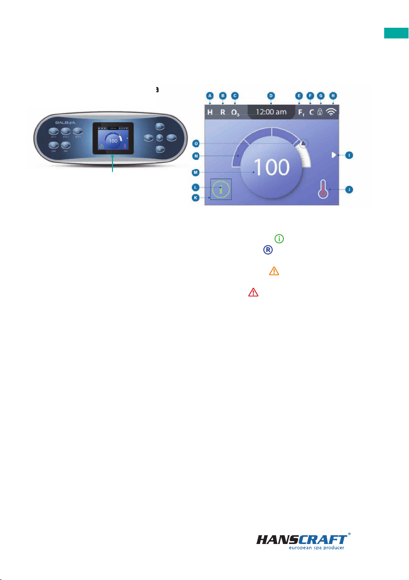
5.1 Main displayed data
5.1 Main displayed data
Atemperature range
– high h
– low l
Bheat mode
– ready r
– rest
– ready-in-rest rr
Cozone running o3
Dtime-of-day
Efilter cycles
– filter cycle 1 f1
– filter cycle 2 (optional feature) f2
– filter cycles 1 & 2 f+
Fcleanup cycle (optional feature)
Gpanel locked and/or settings locked
Hwifi (local or cloud connection)
Inavigation arrow
Jheat status
Kselection box
Lmessage (may appear)
– information
– reminder
– error – normal error
or warning
– error – spa will not function until
fixed
Mwater temperature
– fahrenheit temperatures are
displayed without decimal
points (for example, 100 °F is
displayed as 100)
– celsius temperatures are
displayed with decimal points
(for example, 37.5 °C is displayed
as 37.5)
Nwater temperature bar
Oset temperature arrow
IR
Important information about the current state of your spa is displayed on the main
screen. (Not all control systems are confi gured the same. Spa devices, Settings, and
various menu items may vary on your control panel).
main screen
8
Control panel
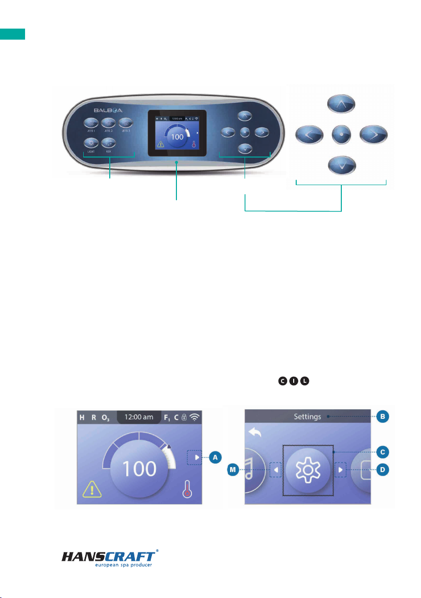
5.2 User interface
SPA device buttons navigation buttons
control panel
SPA device buttons
These buttons control various spa devices, such as jets, lights and/or blowers.
Navigation buttons
Navigate the entire menu structure with the 5 navigation buttons on the control
panel. The names shown to the right refer to the navigation buttons in this user guide.
The names will be written in uppercase letters. Operating or changing a selected item
on the panel screen is generally done with the SELECT button (center button).
Selection box
The selection box is a fundamental navigation tool. It indicates a selected item. Move
the selection box by pressing the UP, DOWN, LEFT, RIGHT navigation buttons. When
an item is selected, press the SELECT navigation button to act upon the selected item.
The next page shows various examples of selected items .
I. II.

9
Control panel
Menu navigation
The right navigation arrow on the main screen indicates a menu. Press the RIGHT
navigation button to enter that menu. A selection box indicates that a menu item is
selected. When a menu item is selected, its name appears at the top of the screen .
In this example the Settings menu is selected. Press the SELECT navigation button to
enter the settings window .
Navigation arrows
Navigation arrows indicate more menu items. Each navigation arrow
corresponds to a navigation button (view page 8). For example, the right navigation
arrow corresponds to the RIGHT navigation button. The left navigation arrow
corresponds to the LEFT navigation button, etc.
Back button
Use the Back button to navigate back in the menus. Use the navigation buttons to
select the Back button. The selection box indicates that the Back button is selected.
Press the SELECT navigation button.
On/Off switches
In this example the Reminders setting has an On/O switch . When the Reminders
setting line is selected, press the SELECT navigation button to turn the switch On/O .
In this example the switch is On .
Select, Save, Cancel
Select one of these columns with the RIGHT and LEFT navigation buttons. Change
the selected setting with the UP and DOWN navigation buttons. After you change the
settings, choose the Save button and press the SELECT navigation button. After you
press SELECT, the change is complete. If you decide to cancel your new settings, select
the Cancel button and press the SELECT navigation button.
III. IV.
10
Control panel
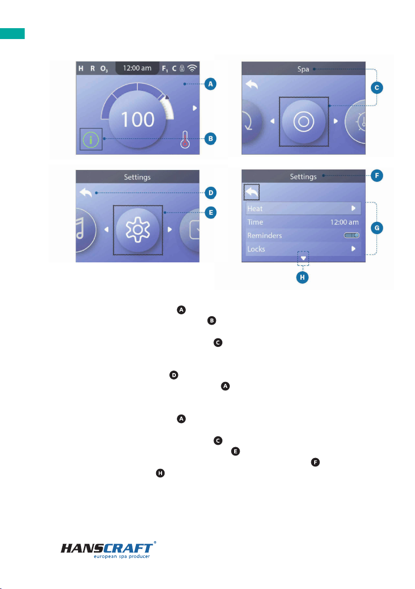
Navigate the Main menu
1 Start from the main screen , and press the RIGHT navigation button to enter
the Main menu. If the selection box is on the Message icon, you need to press
the RIGHT navigation button twice to enter the Main menu.
2 Spa is the rst item in the Main menu . Continue pressing the RIGHT navigation
button to view all items in the main menu.
3 If you want to navigate back to the main screen, press the UP navigation button
to select the Back button . Once the back button is selected, press the SELECT
navigation button and the main screen will appear.
Navigate the Settings menu
1 Start from the main screen , and press the RIGHT navigation button to enter
the Main menu.
2 Spa is the rst item in the Main menu . Continue pressing the RIGHT navigation
button until the Settings menu is selected .
3 Press the SELECT navigation button to enter the Settings menu .
4 The navigation arrow indicates more Settings. Press the DOWN navigation
button to scroll down the list.
I. II.
IV.III.

11
Control panel
Press-and-Hold
If you need to navigate a long list, press-and-hold the navigation button. For example,
press-and-hold the DOWN navigation button to scroll down the Settings menu list .
The navigation arrow indicates more menu items.
View Message Screen
1 Start from the main screen , and press the LEFT navigation button to select the
Message icon .
2 Pressing the SELECT navigation button to view the message screen.
3 The message screen may have an Exit button or a Clear button. Select the button on
the screen and press the SELECT navigation button. (View “Exit and Clear Buttons”
on page 28 for more information).
5.3 Run spa devices
I.
III.
II.
There are two ways to run spa devices.
a) Run spa devices by pressing any of these buttons .
b) Run spa devices from the Spa screen by following these steps.
– Navigate to the Spa menu . (View “Navigate the Settings menu” on page 10)
– Press the SELECT navigation button to view the Spa screen . Each icon
shown in the Spa screen represents a spa device.

12
Control panel
Filtration and ozone
If your spa does not have a circulation pump, pump 1 low and the ozone generator
will run during a filter cycle. If your spa has a circulation pump, the ozone will run
with the circulation pump. Many control systems are factory-programmed with
one filter cycle that will run in the evening (assuming the time-of-day is properly
set) when energy rates are often lower. The filter cycle time and duration are
programmable (view chapter 5.6). A second filter cycle can be enabled as needed.
At the start of each filter cycle, any additional water devices (such as pumps and
blower) will also run briefly to purge its plumbing to maintain good water quality.
Freeze protection
If the temperature sensors within the control system’s heater detect a low enough
temperature, then the pump(s) and the blower automatically activate to provide
freeze protection. The pump(s) and blower will run either continuously or periodically
depending on conditions. In colder climates, an optional additional freeze sensor may
be added to protect against freeze conditions that may not be sensed by the standard
sensors. Auxiliary freeze sensor protection acts similarly except with the temperature
thresholds determined by the switch. See your dealer for details.
Cleanup cycle (Optional)
When a pump or blower is turned on by pressing a button on the panel, a clean-up
cycle begins 30 minutes after the pump or blower is turned O or times out. The pump
and the ozone generator will run for 30 minutes or more, depending on the control
system. On some control systems, you can change this setting.
5.4 Spa behavior
– Select JETS 1 . When you select an icon, its name appears at the top of the
screen .
– Press the SELECT navigation button to run the spa device.
The spa device is running.
If you want to navigate back to the main screen, select the Back button and press
the SELECT navigation button. The main screen will appear. The functionality of each
spa device may vary. For example, some devices may have a single speed or state,
while other spa devices may have multiple speeds or states. Your spa con guration
will determine the number of spa devices and the functionality of each device. One
Spa screen can display a maximum of six devices. If your spa has more than six,
a menu arrow will appear . Press the RIGHT navigation button to view and/or run
the other spa devices.

13
Control panel
5.5 Settings menu
Pumps
Press the JETS button once to turn Pump 1 On or O , and to shift between low-speed
and high-speed if equipped. If left running, Pump 1 will turn O after a time-out
period. If your spa does not have a circulation pump, Pump 1 will run at low speed when
the blower or any other pump is on. If the spa is in Ready Mode (
view chapter
5.8.2),
Pump 1 low may also activate for at least 1 minute every once in a while to detect the
spa temperature (polling) and then to heat to the set temperature if needed. When the
low-speed turns on automatically, it cannot be deactivated from the panel, however
the high speed may be started.
I.
II.
III.
III.
IV.
V.
IV.
V.

14
Control panel
Fine tune your spa with a wide variety of settings
Navigate to Settings to view and/or control your spa. (View chapter 5.2, on page 10,
“Navigate the Settings menu”). This is an example of a Settings list . Your Settings list
may vary.
HEAT
Make sure your spa is heated and ready to enjoy with Heat Settings (View chapter 5.8.1).
TIME
Set the Time to insure scheduled features have proper timing (View chapter 5.7).
REMINDERS
Reminders are helpful spa maintenance messages that display periodically.
LOCKS
Lock the Panel and/or Settings (View chapter 5.10).
FILTER
Keep your spa water clean and ready to enjoy by setting Filter Cycles (View chapter 5.6).
HOLD
Hold is used to disable the pumps during service functions like cleaning or replacing
the lter. Hold Mode will typically last for 1 hour unless the mode is exited manually.
You can see how much longer Hold will last at the bottom of the screen (for example,
“Holding for 0:58”). If you exit this screen, Hold Mode ends. If spa service will require
more than an hour, it may be best to simply shut down power to the spa.
Drain mode (optional)
Some spas have a special feature that allows Pump 1 to be employed when draining the
water. When available, this feature is a component of Hold.
CLEANUP CYCLE (Optional)
When a pump or blower is turned On by a button press, a cleanup cycle begins
30 minutes after the pump or blower is turned O or times out. The pump and the
ozone generator will run for 30 minutes or more, depending on the system. You can
change this setting on some control systems. If cleanup is set to zero hours, this
feature will be disabled. (Cleanup is not included with all control systems, and control of
cleanup is not included with all control systems that have cleanup).
UNITS
Specify Time and Temperature Units . The temperature choices are Fahrenheit or
Celsius. The time display choices are 12 hour or 24 hour.

15
Control panel
5.6 Set filter cycle times
LANGUAGE
Select from a variety of languages .
PANEL
Set how long it takes the panel to go to sleep after the last activity. The default is
30 minutes . Turn On/O the panel lights . Control the brightness of both the
panel lights and the panel display together .
DIAGNOSTICS
Spa technicians can nd useful information and features in Diagnostics
(View chapter 5.11).
I. II.
III. IV.
Follow these steps to set the Filter Cycles:
1 Navigate to Filter .(View chapter 5.2, on page 10, “Navigate the Settings menu”)
2 Press the SELECT navigation button to view the Filter screen .
3 Select the start time for lter Cycle 1 . Press the SELECT navigation button to
view the time controls .
16
Control panel
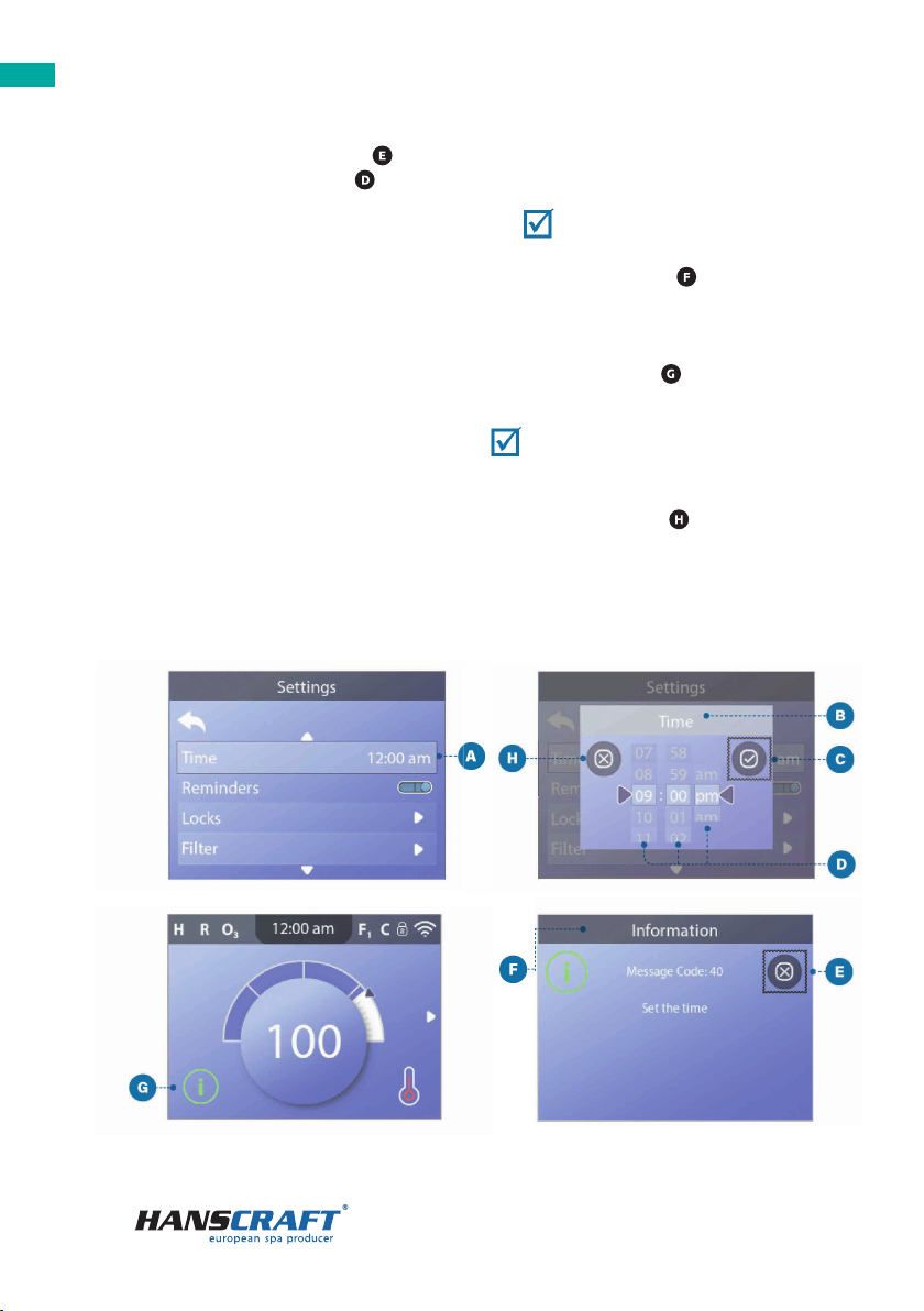
5.7 Set time-of-day
4 Enter your time settings with the navigation buttons.
5 Select the Save button and press the SELECT navigation button.
You have set the start time for lter Cycle 1.
If you do not want to save your settings, select the Cancel button and press the
SELECT navigation button.
6 Follow the same process to change the other filter time settings if desired.
7 Once all of the time changes are set, select the Save button and press the
SELECT navigation button.
You have set all of the lter Cycle times.
How can you tell if Filter Cycle 2 is enabled?
Filter Cycle 2 is enabled when a white ring appears around the 2 . In this example
there is no white ring, so Filter Cycle 2 is disabled. Filter Cycle 2 is disabled by default
on many spas.
I.
III. IV.
II.

17
Control panel
Be sure to set the time-of-day
Setting the time-of-day can be important for determining water ltration times and
other background features.
Follow these steps to set the time-of-day:
1 Navigate to Time . (View chapter 5.2, on page 10, “Navigate the Settings menu”)
2 Press the SELECT navigation button, and the time screen will appear .
3 Use the navigation buttons to adjust your settings .
4 Select the Save button and press the SELECT navigation button.
You have set the time-of-day.
If you do not want to save your settings, select the Cancel button and press the
SELECT navigation button.
If time-of-day has not been set, this information icon appears . Select the
Information icon and press the SELECT navigation button to view the corresponding
message in the Information screen . Select the Exit button and press the SELECT
navigation button to exit the Information screen. You can choose a 12-hour or 24-hour
time display (View chapter 5.5, on page 15, UNITS). If you choose 24-hour time, “am”
and “pm” are removed. CE control systems default to a 24-hour time display.
5.8 Heat settings
Keep your spa heated and ready to enjoy, or keep it cool and save energy.
Heat settings help you do both.
Heat settings are divided into two groups:
– Heat modes
– Temperature ranges
5.8.1 Heat modes
There are three Heat modes
READY MODE
Ready Mode usually keeps the water temperature close to the set temperature
24 hours a day. If you use your spa consistently, you probably want to use Ready Mode.
REST MODE
Rest Mode only heats the water during lter cycles. If you do not use your spa for an
extended period of time, you may want to use Rest Mode.
18
Control panel
TEMP RANGES
High range
8 0 °– 10 4 ° F
26 , 5 ° – 4 0 , 0 ° C
Low range
50 °– 99 ° F
10, 0 °– 3 7, 0 ° C
5.8.2 Heat modes
Di erent high and low temperature ranges may be determined by the manufacturer.
Freeze protection is active in high and low ranges.
I. II.
READY-IN-REST MODE
This mode is a sub-feature of Rest Mode. When your spa is in Rest Mode, and you press
the JETS 1 button, Rest Mode will automatically switch to Ready-In-Rest Mode for one
hour. During this hour the control system will attempt to keep the water temperature
close to the Set Temperature.

19
Control panel
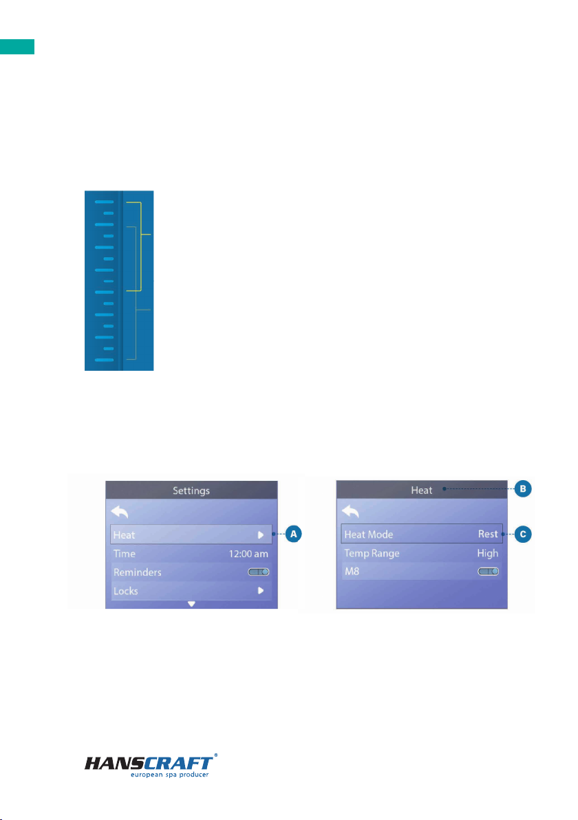
Follow these steps to view the current heat mode and/or change the heat mode:
1 Navigate to Heat . (View chapter 5.2, on page 10, “Navigate the Settings menu”)
2 Press the SELECT navigation button to view the Heat screen . The current heat
mode will appear here . In this example the current heat mode is REST.
There are two heat modes to choose from: READY, REST.
3 Press the SELECT navigation button to change the heat mode to READY .
You have set the heat mode to READY.
The change takes effect immediately. No need to press a Save button. READY-IN-REST
Mode is a third heat mode. But, it is a sub-feature of REST Mode and is not selectable
from the panel menu. The only place you can see whether you’re in READY-IN-REST
Mode is on the main screen, where it shows all three heat modes in icon form. If you
are in READY-IN-REST Mode, and you want to cancel it (ie, you want to return to REST
Mode), just go view the current heat mode (where it will say REST Mode) and exit.
That simple action takes you back to REST Mode
III. IV.
Where can I view the current heat mode on the main screen?
The current heat mode is displayed here with an icon . In this example the current
heat mode is READY. The following list shows which icons may appear on the main
screen.
Heat mode icons
READY: R/ REST:
IR
/ READY-IN-REST: RR

20
Control panel
5.8.3 Temperature ranges
Follow these steps to view the current temperature range and/or change the
temperature range:
1 Navigate to Heat . (View chapter 5.2, on page 10, “Navigate the Settings menu”)
2 Press the SELECT navigation button to view the heat screen . The current
temperature range will appear here . In this example the current temperature
range is Low. There are two temperature ranges to choose from: High, Low.
3 Press the SELECT navigation button to change the temperature range from Low
to High .
You have set the temperature range to High.
The change takes e ect immediately. No need to press a Save button.
Can I see the current temperature range on the main screen?
Yes. The current temperature range is displayed here with an icon . In this example
the current temperature range is High. The following list shows which icons may
appear on the main screen.
Temperature range icons
High: H/ Low: L
I.
III.
II.
IV.
Table of contents
Other HANSCRAFT Hot Tub manuals


Popular Hot Tub manuals by other brands


Aquatic
Aquatic PAGOSA MOTIF AI6642M Specifications

Four Winds
Four Winds UltraXStream owner's manual

Canadian Spa
Canadian Spa Okanagan owner's manual

Aquatic
Aquatic HOTSOAK 85 ai6032SvhS Specification sheet

glass 1989
glass 1989 MySpa 195 E manual

Jacuzzi
Jacuzzi Tara Whirlpool Bath and Soaking Bath B950 Specification sheet