Hantle 1700w User manual
Hantle USA, Inc.
Operator Manual
Hantle 1700w

Table of Contents Operator Manual
1700w™ (Rev 1)
© Hantle 2010
TABLE OF CONTENTS
1. INTRODUCTION
1.1 Features
1.1.1 About the Hantle 1700w™
1.2 Specifications
Hantle 1700w™ Specifications
1.2.1 Dimensions and Component Locations
1.2.2 Front Panel Identification
1.2.3 Cash Dispensing Unit
1.2.4 Receipt Printer
1.2.5 Main Control Board
1.2.6 Operating Environment
1.3 Warranty/Service
2. INSTALLATION
2.1 Hantle 1700w™ Installation
2.1.1 Unpacking
2.1.2 Physical Installation
2.1.3 Hardware Setup
3. PROGRAMMING
3.1 Initial Setup
3.1.1 Accessing the Operator Function Menu
3.1.2 When An Error Occurs
3.1.3 EPP Keypad
3.2 The Host Setup Menu
3.2.1 Key Management
3.2.2 Set Terminal ID Number
3.2.3 Connect Timer
3.2.4 Set Routing ID Number
3.2.5 Set Host Telephone Number
3.2.6 Health Check Message
3.2.7 Remote Monitor
3.2.8 Trial Day Total
3.3 The System Setup Menu
3.3.1 Set Clock
3.3.2 Optional Languages
3.3.3 Speaker Volume
3.3.4 ISO 1/3 En/Disable
3.3.5 Change Passwords
3.3.6 Device Setup
3.3.7 Set Reboot Time
3.3.8 Serial Number
3.4 Customer Setup Menu
3.4.1 Change Message
3.4.2 BIN Lists
3.4.3 Optional Features
3.4.4 Change Processor
3.4.5 Surcharge Mode
3.4.6 Graphics

Table of Contents Operator Manual
1700w™ (Rev 1)
© Hantle 2010
3.5 Transaction Setup
3.5.1 Dispense Limit
3.5.2 Denomination
3.5.3 Fast Cash
3.6 TCP/IP Setup
4. OPERATION
4.1 Opening and Closing
4.1.1 Opening the Security Door
4.1.2 Closing the Security Door
4.1.3 Opening the top Bezel
4.1.4 Closing the top Bezel
4.1.5 Operating and Changing the Combination Lock
4.1.6 Operating and Changing the Electronic Lock
4.2 Cash Operations
4.2.1 Adding Cash to the Cassette (TCDU)
4.2.2 Emptying the Reject Bin (TCDU)
4.2.3 Adding Cash to the Cassette (MCDU)
4.2.4 Emptying the Reject Bin (MCDU)
4.2.5 Loading the Receipt Printer
4.3 Settlement Menu
4.4 Journal Menu
4.5 Reports Menu
5. DIAGNOSTICS
5.1 Diagnostics Menu
6. CUSTOMER TRANSACTIONS
6.1 Opening Procedure
6.2 Withdrawal Transaction
6.3 Balance Inquiry Transaction
6.4 Transfer Transaction
6.5 Closing Procedure
6.6 Error Recovery
APPENDIX
A. Error Codes
B. Pin Pad layout for Master Key / Download Mode / Clear NVRAM
C. TDES Master Key installation
D. Graphic Advertisements
E. CDU Preventative Maintenance

Introduction Operator Manual
1700w™ (Rev 1)
© Hantle 2010 1.1
Hantle 1700w™
1.1 FEATURES
1.1.1 ABOUT THE Hantle 1700w™
Hantle introduces the next generation in retail ATMs. The Hantle 1700w™ raises the
bar for quality, engineering and design. Built with the philosophies of durability,
reliability and security you’ve come to expect from Hantle, the 1700w™ offers the
absolute best value in its class.
While targeted for lower volume markets, the small footprint design retains all the
standard features of a higher end machine including: Triple DES and ADA
compliance, VISA / PCI or Interac certified encrypting PIN pad (EPP), a voice
guidance system, 56K modem and an integrated lighted topper sign.
Weighing in at over 200lbs, the solidly constructed UL291 Listed – Business Hour
vault provides security and offers the same modular construction for ease of
maintenance.
H/W FEATURES
UL 291 Business Hour Service Vault featuring reinforced steel bottom & dial lock
7” high-resolution, wide-screen TFT LCD
56K modem + Ethernet TCP/IP with SSL encryption
800 note fixed cassette dispenser (TCDU)
1000 note removable cassette dispenser (SCDU)
1700 note removable cassette dispenser (MCDU)
Dual Cassette 3400 note (1700x2) dispenser
DIP type magnetic card reader (EMV Optional)
2¼” Thermal receipt printer
Modular design for easy maintenance
Lighted transaction guidance system
Meets ADA Standards for Height, Reach and Keypad layout
FUNCTIONAL FEATURES
Electronic journal stores over 40,000 transactions
Supports English, Spanish and French languages
Availability for 8 on screen advertisement graphics
Detailed average history report feature
On-screen error code descriptions for easy service
Introduction Operator Manual
1700w™ (Rev 1)
© Hantle 2010 1.2
1.2 SPECIFICATIONS
Hantle 1700w™ SPECIFICATIONS
1.2.1 Dimensions and Component Location
Fig. 1 Dimensions
WEIGHT: 206 lbs.

Introduction Operator Manual
1700w™ (Rev 1)
© Hantle 2010 1.3
Component Location
1. LCD & Customer Keypad 11. Security Door Handle
2. Card Reader Slot 12. Cash Dispensing Unit
3. Receipt Printer Slot 13. Receipt Printer
4. Cash Tray 14. Main Control Board
5. Front Panel 15. Ear Phone Jack
6. Front Panel Lock 16. Power Supply
7. Security Cover 17. Speaker.
8. Security Cover Lock 18. ADA Board
9. Security Door 19. Card Reader
10. Combination Lock

Introduction Operator Manual
1700w™ (Rev 1)
© Hantle 2010 1.4
1.2.2 Front Panel Identification
Fig. 3 Front Panel Identification
LCD
Screen Size: 7”
TFT LCD
Resolution: 800 x 480 WVGA
Display Characters: 40 x 15 (Standard Characters)
8 LCD Function Keys
KEYPAD
Certified VISA compliant EPP (Encrypting Pin Pad)
10 Alphanumeric, 3,4, CANCEL, CLEAR, ENTER, BLANK Keypads
Voice Guidance Port
Voice assisted operation available through the headphone jack on the front bezel
EPP Keypad
Receipt Printer
Voice Guidance
Lighted
Topper
Function Keys
Card Reader
Lighted Transaction
Guidance
LCD Panel
Introduction Operator Manual
1700w™ (Rev 1)
© Hantle 2010 1.5
1.2.3 Cash Dispensing Unit
Cash Dispensing Unit
(1000 Note - SCDU)
CASH DISPENSING UNIT
Dispensing Speed: 2.5 notes/second
Capacity of 800 new notes (fixed cassette)
Capacity of 1000 or 1700 notes (removable)
Lockable Reject Bin
Double note detect module
*Optional dispensers include:
1700 note removable cassette
(MCDU)
3400 note dual-cassette
(1700x2)

Introduction Operator Manual
1700w™ (Rev 1)
© Hantle 2010 1.6
1.2.4 Receipt Printer
Receipt Printer
RECEIPT PRINTER
Thermal line printer
36 characters/line
Semi-automatic roll paper setting
Motorized front push rollers
PAPER SPECIFICATIONS
One sided thermal paper
Factory paper is thermal side out (but either way will work)
6 inch outside diameter roll
2 ¼” inch wide
Core inside diameter 11/16 inch
21# weight (paper thickness)

Introduction Operator Manual
1700w™ (Rev 1)
© Hantle 2010 1.7
1.2.5 Main Control Board
Samsung S3C2440AL-40 RISC 32-bit CPU
64 MB RAM
WinCE™ 5.0 Operating System
Modem: 56,000 bps dial-up modem
TCP/IP Ethernet connection - Onboard SSL
Electronic Journal: 40,000 transactions
Battery back-up for set-up parameters (NVRAM)
Real time clock
1.2.6 Operating Environment
POWER REQUIREMENTS
110/220 VAC ±10%, 50/60 Hz, 145 Watts
POWER CONNECTIONS
For warranty purposes, the Hantle 1700w™ series ATM must be connected to a
dedicated power circuit. This circuit must consist of line, neutral, and ground leads
connected directly to the power circuit breaker panel. This circuit should not be
shared with any other equipment. Use of a surge protector or uninterruptible power
supply is recommended.
PHONE LINE REQUIREMENTS
The Hantle 4000 series ATM should be connected to a dedicated phone line. This line
must be a direct-dial analog line. Make sure to disable any voice-mail included on
that phone line. This line should not be shared with any other equipment at the
location. Use of shielded (CAT5) phone cable is recommended for best performance
and to reduce the chance of interference. ‘Digital’ phone lines are NOT supported.
NETWORK (TCP/IP) REQUIREMENTS
For connection to processor via TCP/IP, use an Ethernet Patch-Cable (not included).
The ATM must connect to a device (Router) that can provide DHCP support unless a
static IP address is assigned by the service provider. It is recommended the ATM
connect to a broadband router (Linksys, Netgear, Belkin) or similar device rather
than directly to a Cable/DSL modem. For advanced or corporate networks, provide
the IT staff with ATM Host IP address and Host Port information (available from your
ISO).
TEMPERATURE
In storage : 32°F - 123°F (0°C ∼49°C)
While operating : 40°F - 95°F (5°C ∼35°C)
HUMIDITY
In storage : 10% < RH < 90%, non-condensed
While operating : 15% < RH < 85%, non-condensed

Introduction Operator Manual
1700w™ (Rev 1)
© Hantle 2010 1.8
1.3 WARRANTY/SERVICE
MANUFACTURERS WARRANTY
Hantle USA, Inc. provides a limited one-year parts warranty and a limited 30 day
labor warranty for the 1700w™ series ATM. Hantle guarantees your 1700w™ model
ATM to be free from defects in materials and workmanship.
The one-year parts warranty and 30-day labor warranty periods will begin 15 days
from the shipping date.
WHAT IS COVERED:
· Cash Dispensing Unit (CDU) and Cash Cassette
· Receipt printer (SHU)
· LCD module
· Magnetic Card Reader (MCR)
· EPP Keypad
· Power Supply
· Mainboard (CE)
· Lock and locking mechanism **LIMITED 90 DAY WARRANTY**
Dial and Electronic locks will be covered by a limited 90-day warranty beginning
15 days from shipping date. Should the lock fail under normal use, Hantle will
replace the lock only. Services required to open the vault and or replace the lock
are at the expense of the ATM owner.
WHAT IS NOT COVERED:
· Power cable and modem cable
· Key lock and key
· Plastic Bezels
· Software upgrade
· Receipt printer jam
· Note jam
· Forgotten password or combination of lock
· Any damages from misuse, improper installation, and vandalism
· Any damages from “brown out” or low power, lightning, or any other ‘acts of God’
Your distributor/dealer may offer an enhanced or extended warranty in addition to
the original manufacturers one-year warranty. Once the manufacturers warranty
has expired, all claims for warranty service must be resolved directly between the
distributor/dealer and the ATM owner.
OBTAINING SERVICE: If you have any problems or questions about your Hantle
ATM, your dealer or distributor is your primary contact for assistance/service. Your
manufacturers warranty is provided through your dealer or distributor.

Section 2: Installation Operator Manual
1700w™ (Rev 1)
© Hantle 2010 2.1
SECTION 2: INSTALLATION
2.1 Hantle 1700w™ INSTALLATION
2.1.1 UNPACKING
Ste
p
1
Once the ATM is unpackaged, do not discard the packaging materials until you have
verified any shipping damage claim. Contact your distributor immediately if you see
any shipping damage.
Ste
p
2
Verify the contents carefully with the packing list to be sure all items listed are
included. Notify your distributor of any shortages.
2.1.2 PHYSICAL INSTALLATION
To install the Hantle 1700w™ ATM, review the following steps:
Step 1
Place the system on a flat surface. The system has a tendency to tip over if the
surface is over 10 degrees. Be careful when opening the top or bottom of the
machine as it will be off balance.
Step 2
Use the holes in the bottom of the vault to mark and drill the appropriate sized holes
for the anchors you will be using. (Anchors are not included). Hantle does not
recommend a particular size or type of anchor as each installation is different
however maximum anchor diameter is ½
Step 3
Install the anchors into the ground according to the anchor bolts locate sheet (4
places). See manufacturer’s instructions for anchor installation.
Step 4
Place the 1700w™ ATM on top of the anchors.
Step 5
Open the Security cover with the key provided. See page 4.1 for Opening and
Closing instructions.
Section 2: Installation Operator Manual
1700w™ (Rev 1)
© Hantle 2010 2.2
Step 6
Using the supplied combination (see lock manual for default combination), open the
security Door. This combination should be changed as soon as possible. Refer to
page 4.5 (dial) or 4.7 (electronic) for instructions on opening or changing the lock.
Step 7
After the anchor nuts are in place, according to the anchor holes on the bottom of
the ATM, secure the anchor bolts snugly. Do not over tighten anchors as it may
distort the vault and cause problems with the door linkage.
END
2.1.3 HARDWARE SETUP
Step 1
Verify the power voltage (115/220V) to be used and set the
appropriate voltage on the power supply. Default will be
115V. The default setting should be 115V
Step 2
Verify that the telephone line to be used for the ATM is in proper working order.
Hantle recommends the use of shielded (CAT5) phone line in locations with close
proximity to other appliances.
Step 3
Open the security door and remove any shipping materials and note any warning or
installation instructions. See page 4.1 for assistance.
Use this key (2 included) to
open the top and bottom bezels
Cassette key
(fixed cassette)
Cassette key
(removable cassette)

Section 2: Installation Operator Manual
1700w™ (Rev 1)
© Hantle 2010 2.3
Step 4
Remove the cash cassette from the box (removable cassette dispensers only). Fill
the cassette or cash drawer with the appropriate amount of notes, and carefully
place it in the Cash Dispensing Unit. Place the appropriate denomination label on the
front of the cassette. See page 4.9 for instruction.
Step 5
Before closing the vault, thoroughly test the combination lock by locking and
unlocking the lock several times. It is much easier to diagnose potential lock
problems before shutting the door.
Step 6
Open the top of the ATM. Place the receipt paper in the Receipt Printer. The paper
prints only on one side (shiny side) always check the roll when you install paper.
Place the roll so that the coated side (shiny side) will be facing up. See page 4.12 for
paper loading instruction.
Step 7
Connect the Power cable and the telephone cable to the appropriate outlets on the
wall. Verify that the AC power outlet is grounded. If you are installing the
illuminated topper, make sure to completely install the power cord into the A/C Out
plug on the power supply. The socket takes an extra push to fully seat the plug.
Step 8
Turn the power on and verify that all systems are operational. If any part on the
system or its programming is not operational, an error code will be displayed. If an
error code is displayed, corrective action will be listed below it. If the error cannot
be corrected, please contact your distributor. If no error code is displayed, enter the
Operator Function Menu and view the Error Summary (see programming section).
END

Section 3: Programming Operator Manual
1700w™ (Rev 1)
© Hantle 2010 3.1
SECTION 3: PROGRAMMING
3.1 INITIAL SETUP
3.1.1 ACCESSING THE OPERATOR FUNCTION
Step 1
To access the Operator Menu, you do not need to hold down the 3 keys (CANCEL,
CLEAR, ENTER) and then press 1 – 2 – 3. Just press the following keys in order
[ENTER] – [CLEAR] – [CANCEL] – [1] – [2] – [3].
Note: The Operator Function menu can only be accessed when the machine is either
in service (“insert your card” screen) or out of service. If the machine is attempting
to connect to the host or initializing, you will not be able to use the key commands to
access the Operator Function Menu.
If you have trouble accessing the Operator Menu, power off the ATM and then either
open the vault door or remove the paper from the printer and power back on. This
will force the ATM to the Operator Menu.
Step 2
Once you successfully completed the key
combination, you will be prompted to enter a
password. There are 3 levels of passwords.
•Operator Password (allows access to basic
menu structure)
•Service Password (allows access to basic
and diagnostic menus)
•Master Password (allows access to all
menus including setup parameters)
You must press ENTER key after typing
the password!
Passwords are very important to maintaining
security for your ATM. Your
dealer/distributor will provide you with
default password information.
WARNING: Hantle USA, Inc. highly recommends changing your
passwords from default as soon as possible. Keep all passwords safe and
restrict access to non-authorized personnel.
Passwords MUST be 6 digits in length, use of anything other than a 6 digit
password may cause the passwords to revert back to factory default.

Section 3: Programming Operator Manual
1700w™ (Rev 1)
© Hantle 2010 3.2
Step 3
Shown the left is the complete Operator
Function menu, depending on which
password you entered (operators, service,
master) you may not see certain functions.
For example, if you use an operator password
you will not see the Host Setup button, as
you will not have access to that menu.
END

Section 3: Programming Operator Manual
1700w™ (Rev 1)
© Hantle 2010 3.3
3.1.2 WHEN AN ERROR OCCURS
Step 1
When an error occurs, please press
[ENTER] – [CLEAR] – [CANCEL] – [1] – [2] –
[3].
NOTE: If the machine goes out of service,
the error code will not always appear on the
screen. If you do not see an error code,
enter operator function and go to reports.
Look in the error summary for error codes.
Step 2
“ENTER PASSWORD” will be displayed. Enter
the Master, Service or Operator Password to
continue.
Contact your distributor for default
passwords.
Remember to press ENTER key after
typing password!
Step 3
When the screen is in current display, press
“OP” key to access the “OPERATOR
FUNCTION.”
END

Section 3: Programming Operator Manual
1700w™ (Rev 1)
© Hantle 2010 3.4
3.1.3 EPP KEYPAD
Fig. 1 Hantle 1700w™ keypad and LCD display
NOTE: LCD Keypads are no longer used for Master Key letters. Please
see addendum included with this manual.
Shift Status 0 1 2 3 4 5 6 7 8 9
Upper
+
-
=
Space
Q
Z
A
B
C
D
E
F
G
H
I
J
K
L
M
N
O
P
R
S
T
U
V
W
X
Y
F1
Alphabet
Upper Lower
+
-
=
Space
q
z
a
b
c
d
e
f
g
h
i
j
k
l
m
n
o
p
r
s
t
u
v
w
x
y
F5
Number
Special
Number
0
(
)
1
[
]
2
{
}
3
<
>
4
,
.
5
!
$
6
‘
“
7
%
*
8
:
;
9
?
/
F3
Alphabet
Lower
Fig. 2 Keypad Character Table

Section 3: Programming Operator Manual
1700w™ (Rev 1)
© Hantle 2010 3.5
3.2 HOST SETUP
The Host Setup menu provides access to the parameters necessary to connect the
ATM to the processor. Master Password is required to access most of these options;
however Service password allows basic access for troubleshooting purposes.
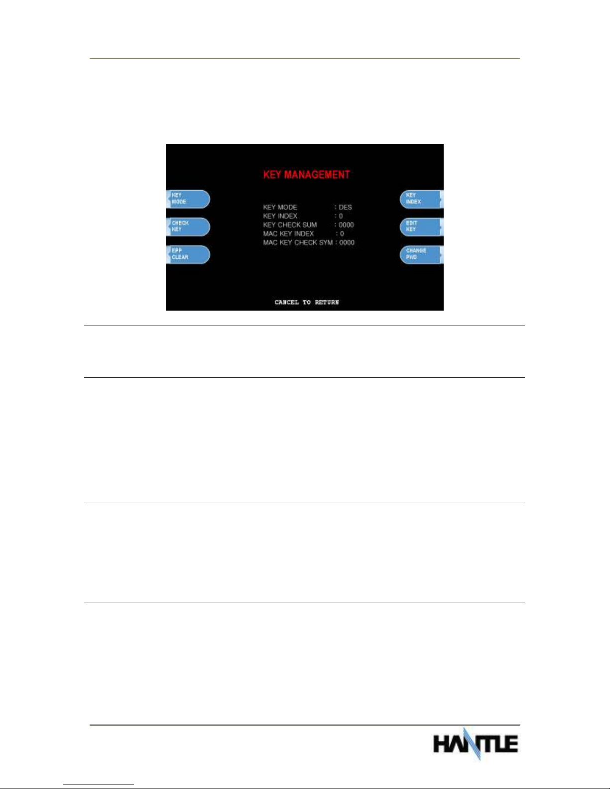
3.2.1 KEY MANAGEMENT
Access to Key Management requires entering a “Secure Mode” which engages
additional security measures (per VISA specification) to prevent Master Key
tampering. Make note of these changes as it does affect how keys are entered.
Entering Key Management requires two 6-digit passwords. By default these will be
“000000” for part #1 and “000000” for part #2.
If a mistake is made entering the “Secure Mode” password, you will be prompted to
wait 30 seconds to reattempt.
NOTE: In compliance with PCI specifications, you must change the Secure Mode
Passwords from default before any Master Keys can be entered. After changing the
Secure Mode Passwords, you must exit completely from the Operator Menu, and
reboot the machine. After this step, you can enter Master Keys.
Section 3: Programming Operator Manual
1700w™ (Rev 1)
© Hantle 2010 3.6
Successful entry of both passwords will grant access to the Key Management screen.
From the moment the Key Management area is entered, a 5 minute timer begins. At
the end of 5 minutes, regardless of what you are doing (entering a master key for
example) the Key Management area times out and you will be taken back to the Host
Setup menu.
KEY MODE
This option sets the type of master key you will be loading (TDES, DES, MAC etc.)
Refer to Addendum C for Key Mode descriptions and instructions.
MASTER KEY INDEX
The ATM will hold up to 16 individual Master Keys. Check with your processor to find
if they are expected to be at a certain location. For example Coredata is always
installed at index #9, most other processors are installed at index #0 or #1. The
ATM will only use the key that the index is set to regardless of how many keys are
installed. To set the index simply press the button labeled Master Key Index and
then enter the number you want it set to (enter as a 2 digit number ... 00, 01, 02,
10, 11 etc.) press Enter when done. Press Check Master Key to see a list of
currently installed keys.
CHECK MASTER KEY
This will show the list of available master keys and their appropriate checksums. The
checksum is a 4 digit number calculated from the two 16-digit numbers of your
master key that provides a means to verify the master key is correct. When your
processor provides your Master Keys, they will also give you the 4 digit checksum. If
after entering your Master Key this checksum does not match, try reentering your
master keys or contact the processor.
EDIT MASTER KEY
This is where you enter your two 16-digit Master Keys (provided by your processor).
After pressing Edit Master Key, you will be prompted to enter an index where you
want this key stored. If you do not know which index to use, contact your dealer or
processor. Generally, you should use index 0 or 1 unless otherwise instructed.
Table of contents
Other Hantle Cash Counter manuals


Popular Cash Counter manuals by other brands

Steinberg Systems
Steinberg Systems SBS-CC-500 user manual

Axel
Axel MC726 Series quick start guide

Agilent Technologies
Agilent Technologies 5385A datasheet

MZ electronic
MZ electronic EV-030 Instructions for use

radiotec
radiotec rapidcount M 120 instruction manual

Yoosol Electronics
Yoosol Electronics PRIMO-P2 Operation manual


ascobloc
ascobloc ASCOLINE 700 Series operating instructions

Lofrans
Lofrans Iris Installation and user manual

Nautilus Hyosung
Nautilus Hyosung Ocean ATM NH2600SE Quick reference guide

AlphaLab
AlphaLab AIC2 manual

Kübler
Kübler CODIX 541 operating instructions

Nautilus Hyosung
Nautilus Hyosung MX5600 installation manual